Aulne study plan Rowboat 4.12 m - François Vivier
←
→
Page content transcription
If your browser does not render page correctly, please read the page content below
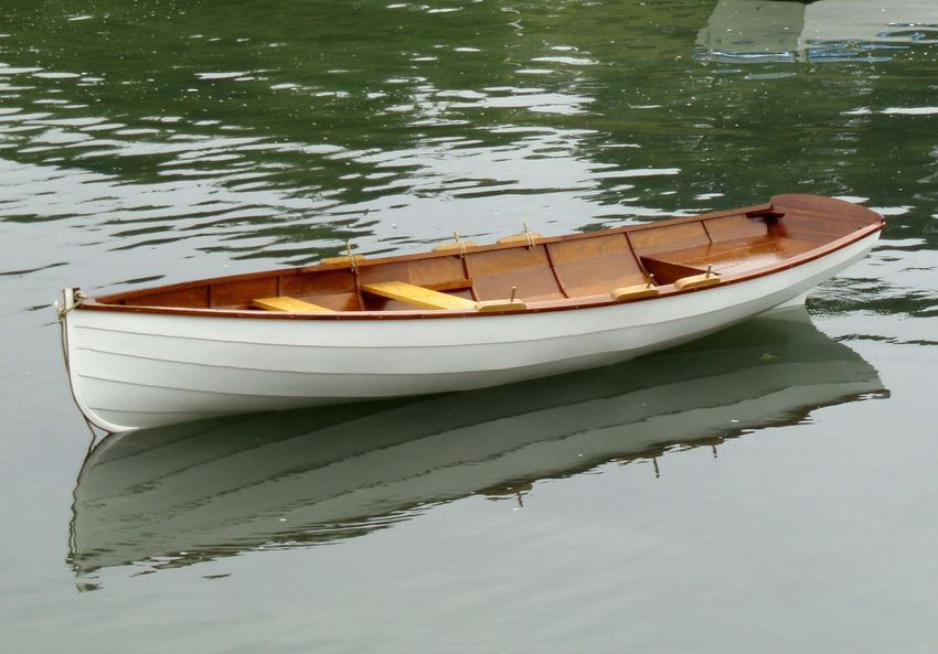
Aulne study plan
                                   Rowboat 4.12 m

                                 ©   François Vivier – March 2021
François Vivier Architecte Naval – SARL au capital de 8 000 € - Siren : 451 456 669 RCS Saint Nazaire
                    7, avenue des Courtils, 44380 Pornichet - tél : 06 74 54 18 60
                         e-mail : fr@vivierboats.com – www.vivierboats.com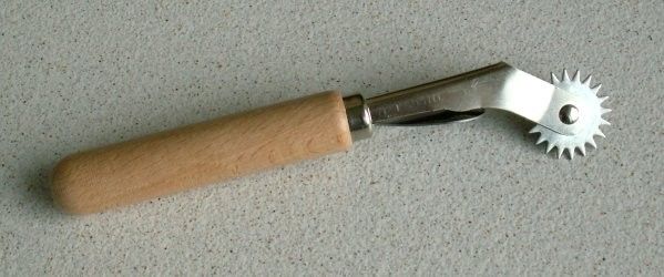
March 2021                                                         Building Aulne                                                           Page 2/7

1.      Plan package content
Aulne plan package is constituted of a 12 pages manual, of which you will find hereafter some extracts, and the following docu -
ments. Documents included, as a whole or partly, in the study plan are underlined in grey and are given as examples. Drawing are
reduced in size.

1.1. The present manual

1.2. Appendices
  Num       Rev      Titre                                                                                  Date                            Pages
   1         2       Timber list                                                                            26 March 2021                     2
   2         4       Plywood panels and part list                                                           26 March 2021                     7

1.3. Manual of “wooden boatbuilding” sheets (mainly in French)
These documents are extracts from my book on wooden boat construction, “Construction bois les techniques modernes” (in
French). Though only a few are presently translated, equivalent information in English is available from other sources. For ex -
ample, the websites of epoxy suppliers give comprehensive information in regard to saturation, gluing, filleting, and sheathing.
Sheet 44 is already translated and I intend to translate other ones. If you need some technical advice, please tell me and I will an -
swer your questions.
  Num       Rev      Titre                                                                                  Date                            Pages
   05        0       Imprégnation époxy                                                                     25 sept. 03                       2
   06        0       Collages et joints congés                                                              14 octobre 03                     2
   07        0       Stratification sur bois                                                                15 novembre 03                    4
   08        0       Imprégnation et collage : solutions par temps froid                                    12 novembre 03                    3
   15        1       Scarfs des panneaux de contreplaqué                                                    9 novembre 03                     2
   16        0       Pièces en lamellé-collé                                                                30 décembre 03                    4
   22        0       Montage de la structure sur chantier                                                   8 avril 04                        8
   31        1       Bordé en petites lattes                                                                19 juin 04                        5
   41        0       Brochetage d'un bordé                                                                  21 janvier 04                     3
   43        0       Tenue provisoire des clins                                                             6 novembre 03                     1
   44        1       Lapstrake fitting                                                                      6 december 2006                   3
   63        2       Membrures lamellées-collées in-situ                                                    28 octobre 05                     4
   71        0       Bancs et planchers                                                                     7 octobre 03                      1
   81        0       Mâts et espars ronds                                                                   17 octobre 2003                   3
   91        0       Peintures et vernis                                                                    18 novembre 03                    3

1.4. Plans format A3
  Num       Rev      Tittle                                                              Scale                  Format                  Date
   01        1       Hull lines                                                          1/15                     A3               15 March 2006
   21        3       General arrangement                                                 1/12                     A3               26 March 2021
  C12        2       Building frame clinker version                                      1/15                     A3                20 July 2006
  L12        0       Building frames strip version                                       1/12                     A3                11 April 2013
   36        0       Rowing oars                                                         1/10                     A3              27 February 2006

              This document is the property of François Vivier Architecte Naval. It shall not be copied, transmitted to any other person,
                                  nor published as a whole or partly, without the written consent of the architect.
March 2021 Building Aulne Page 3/7
2. Main characteristics
2.1. Dimensions
Hull length 4.12 m
Waterline length 3.92 m
Breadth 1.38 m
Depth over rabbet line 0.48 m
Light weight (hull 4 mm ply, without oars) 60 kg
Light weight (strip planked hull, without oars) 80 kg
2.2. Boat presentation
Aulne has been designed to be:
✗ A pretty row-boat, for one or two rowers, able to sea or river.
✗ Of modern wood-epoxy construction, still keeping the look and character of a classic.
✗ Transportable on a light trailer of on a car top.
2.3. Construction method
Aulne may be built either as a clinker plywood of strip planked hull.
Clinker construction is made with 4 to 6 mm thick plywood. There are only 5 strakes per side, for an easy work. 4 or 5 mm
plywood, generally available with 3 veneers only, is light but weak. It is to be chosen if easy handling is a priority. 6 mm ply -
wood, with 5 veneers, gives a stronger hull. The extra weight from 4 to 6 mm is 8 kg.
The transverse structure is made of two laminated frames and two bulkheads at ends of buoyancy compartments. Addi -
tional temporary station moulds are added to help laying down the hull planking.
The strip planked version is made of 9 mm thick strips, with outside sheathing and, optional inside sheathing. The strips
are laid down on a building frame made of 12 station moulds.
2.4. Building time, tools
It is difficult to give an estimate of the time of construction, so much this one varies from one builder to another, according
to the experience possibly gained during former constructions. The tools you have at disposal and you are able to master
influence the working time. Some boats are true works of art, others are rather of simple and rustic style.
The cutting up of timber takes also time which could be sub-contracted. Then, only basic portable tools are necessary: drill,
screw driver, jigsaw, without forgetting a good quantity of screw clamps.
The building time is about 200 hours, using precut timber and full-size patterns. Construction time may be doubled for a
first construction project and if you want a high quality finish. These times are complete, including oars and painting. To
build yourself such a boat supposes that you are looking mainly for the satisfaction of a beautiful work, without being to
much worried by time constraint. The strip planked version requires additional building time.
2.5. Compliance to regulations
Aulne is designed in compliance with the requirements of the European Recreative Craft Directive for the design category
D, with a crew between 1 and 3 persons. She is fitted with two watertight compartments and is designed to be recovered
by the crew in case of capsize. In particular, bilge keels have hand grips for that purpose.
The definition of the design category is pointed out below:
Category D (Sheltered waters): designed for voyages in close coastal waters, small bays, lakes, rivers and canals where con -
ditions up to and including wind force 4 and maximum wave heights up to and including 0,3 m may be experienced.
NOTE: The significant wave height is the mean height of the highest one third of the waves, which approximately corres -
ponds to the wave height estimated by an experienced observer. Some waves will be double this height.
This document is the property of François Vivier Architecte Naval. It shall not be copied, transmitted to any other person,
nor published as a whole or partly, without the written consent of the architect.March 2021 Building Aulne Page 4/7
3. Right of use and general information
3.1. Right of use
The purchase of the plan gives the right to build one unit, by an amateur builder. They can be sold only by the naval archi-
tect (François Vivier) or approved partners.
Plan package, comprising the present manual and all the attached documents listed on page 2, is the property of the archi -
tect. Except for the needs of construction or purchases, the documents may not be reproduced, transmitted to a third
party, nor published entirely or partly, without written authorization from the architect.
3.2. Plan number
The plan number, registered on the front page of this manual, is specific to the purchaser and must be recalled in any cor -
respondence with the architect or kit seller.
Please inform the architect when the boat is first launched, and of change of address or ownership while building.
3.3. Liability of the builder
Aulne was designed with care and in full compliance with the European regulations. However, each boat is built under the
whole responsibility of its builder, and sails under the whole responsibility of its crew. Both the architect and kit sellers, if
any, decline any liability in regard to people, legal entities, and property resulting from construction and/or from use of a
boat built from the plans.
3.4. Respect of the weights, scantlings, materials, and buoyancy
Amateur builders should be careful to note the necessity of respecting the plans and specifications, especially scantlings
and choice of materials. Respecting the specifications concerning volumes of buoyancy is an essential condition for compli -
ance with EC regulations.
3.5. E-mail assistance
If you encounter difficulties during construction, or if you have suggestions to make, please feel free to contact the archi -
tect (preferably by e-mail or phone). Specify the number and the date of the plan (see front page). We will answer your
questions and, if necessary, update the plans to benefit other builders.
François Vivier Architecte Naval
7, avenue des Courtils – 44 380 Pornichet - France
tél : 33 (0)6 74 54 18 60
e-mail : fr@vivierboats.com - www.vivierboats.com
Note: I am always happy to receive pictures and news about the boats I have drawn !
3.6. Supplies, kit
Materials and fittings needed for construction, in particular those specific to the boat, can be sourced from my partners
(see my web site): marine plywood, sawn timber, fittings, trailer.
I have observed that to buy a kit allows the amateur builder to avoid bad surprises, un-compliant purchases, high delivery
costs and generally is a cheaper and easier way that to try to source all different materials and equipments.
This document is the property of François Vivier Architecte Naval. It shall not be copied, transmitted to any other person,
nor published as a whole or partly, without the written consent of the architect.March 2021 Building Aulne Page 5/7
4. Full size patterns and kit
4.1. Full size patterns on polyester film
These patterns give the marking of moulds, bulkheads, stem, transom and hull strakes for the clinker version... Bevels are
drawn. Full size patterns allow time saving and better accuracy to build your Aulne.
Attention: to build the boat, you need both the plan and either the full size patterns or a kit.
The support is a polyester film (also said mylar), very resistant to tearing and not subject to humidity variations. Marking
are to be transferred to the plywood sheets for both moulds or plywood parts.
For that purpose, you may use a screwdriver grinded to form a spike. With a hammer, the wood is marked through the
film. You may also use carbon paper spread between film and plywood. An other very efficient method is to use a tracing
wheel as used by dressmakers:
Polyester patterns are delivered in a resistant tube and are to be ordered from François Vivier Architecte Naval SARL ac -
cording to current price list.
4.2. Plywood kit (clinker version only)
The kit includes all the plywood parts necessary to the construction, as well as some moulds, precut on numerically con -
trolled machine. Most parts are at final dimension or require only little fit. Refer to the appendix 1 which gives the nesting
plans of the parts in all panels. The planking strakes are assembled by zigzag joints as shown on the following sketch. You
have only to glue them together and get a plank ready to be placed on board with only adjustments at ends:
Note that if the joints are too tight for bonding, simply grate the keys shown by the arrow.
Attention: To ensure a better strength, it is strongly recommended to sheath the joints (extending by 10 cm) on the inside.
Kit is to be ordered to an authorized partners (see my website).
The building process described in the following pages assumes that the builder works with the full-size patterns. If he has
the kit, some tasks are deleted or simplified.
This document is the property of François Vivier Architecte Naval. It shall not be copied, transmitted to any other person,
nor published as a whole or partly, without the written consent of the architect.March 2021 Building Aulne Page 6/7
5. Summary of the construction process
Before starting the construction, the general process of which is presented in the following pages, it is important to read
the whole manual and plans for a good overall comprehension. That remains true at all stages. A good preparation will
avoid errors, sometimes not easily retrievable, and will save time.
The general process is as follows:
✗ Cut-out the station moulds from chipboard or ordinary plywood panels,
✗ Make the transom and the stem, including false stem
✗ Assemble the building frame
✗ Add the transom, the stem and the keel on the building frame
✗ Lay down the hull planking, plywood clinker or strip planked
✗ Fit the false stem, the skeg, the false keel
✗ Make epoxy fillets and sheathing (strip planked version)
✗ Turn over
✗ Fit the floors, frames, bulkheads, gunwale, rub-rail, floorboards, thwarts...
✗ Painting and varnishing, fittings...
✗ Oars (may be done at any moment)
6. Chronological description of the building process
6.1. Transom
Full-size pattern The transom is made of two layers of 6 mm plywood. It is also possible to have it made of solid wood, glueing
Appendix 1 strips. Then it is thicker (18 mm). The first method is lighter. The solid wood transom is toucher, more beauti -
ful, and it avoids seeing the plywood edges (top of the transom), which may deteriorate when the boat is
Plan 12 turned over.
The transom of the strip planked hull is made of solid wood.
The strips of the solid wood transom are glued as shown:
The full-size pattern shows to inside profile to be cut. It also shows the outside shape and, therefore, the re -
quired bevel. For the clinker version, the transom outline is given for both types of transom, plywood or solid
wood.
It is also possible to make the transom in plywood, but with a top plank in solid wood to get the best of both
ways.
For the clinker version, the full-size pattern shows the place to screw down the cleat intended to receive the
aft deck. This cleat is also used as the mean to locate the transom properly on the building frame. Therefore,
this cleat is to be positioned with care. It is also recommended to bevel the cleat in advance.
For the strip planked version, you only have to mark the main box girder outline on the inside face.
This document is the property of François Vivier Architecte Naval. It shall not be copied, transmitted to any other person,
nor published as a whole or partly, without the written consent of the architect.March 2021 Building Aulne Page 7/7
6.2. Prefabrication of the stem and false stem
6.3. Assembly of the building frame (clinker plywood)
6.4. Assembly of the building frame (strip planked version)
6.5. Clinker plywood planking
6.6. Strip planking
6.7. External completions of the hull
6.8. After turn-over
6.9. Frames
6.10. Buoyancy compartment bulkheads
6.11. Gunwale and rub-rail
6.12. Intermediate floors
6.13. Sets risers and thwarts
6.14. Floorboards and footrests
6.15. Buoyancy compartments
6.16. Painting
7. Equipment
7.1. Oars and thole pins
This document is the property of François Vivier Architecte Naval. It shall not be copied, transmitted to any other person,
nor published as a whole or partly, without the written consent of the architect.Aulne – Annexe 1 – rev 2
Timber list
Items Version Timber Quantity thick. width lengh. Comments
code mm mm mm
Hull planking strips Strips B 120 9 18 4 350 110 Strips if solid wood sheer-strake
Solid wood sheer-strake Strips A 2 12 120 4 350 Option
Transom Clinker A 8 18 42 900 Option , instead of plywood
Transom Strips A 8 18 42 900
Keel All A 1 16 40 4 000
False keel All A 1 24 24 3 850
Skeg, layer 1 All A 1 18 32 1 500
Skeg, layer 2 All A 1 18 32 1 100
Skeg, layer 3 All A 1 18 30 800
Skeg, layer 4 All A 1 18 28 600
Skeg, other layers All A 1 18 26 1 200 Total length
Stem Clinker A 1 12 150 2 000 Or equal (see sketch 1)
Stem Strips A 1 13.5 150 2 000 Or equal (see sketch 1)
Laminated false stem All A 12 2.5 34 950
Laminated frames All A 44 4 24 1 000 Frames linked at centreline by a floor
Laminated frames side by side to bulkheads Strips A 44 4 24 1 000 Frames linked at centreline by a floor
Frame extensions All A 4 45 24 300
Floors All A 7 40 24 500
Breasthook and quarter knees All A 1 18 120 700
Gunwale All A 2 18 25 4 300
Rub-rail Clinker A 2 16 25 4 400 With rabbet 16 X 6 (for 6 mm ply strakes) (option)
Rub-rail All A 2 12 25 4 400 For clinker without rabbet and strips
Gunwale, doubler All A 2 18 25 1 700
Seat riser, fore thwart All A 2 30 50 400
Seat riser, mid thwart All A 2 30 50 700
Cleat under thwart All A 2 30 40 200March 2021 Aulne Appendix 1 - Rev 2 - Page 2/2
Cleat between transom and aft deck All A 1 25 35 1 000
Decks trims All A 2 18 60 1 200 May be cut out into a graceful profile
Cleats under decks All A 1 20 25 3 000 Total length
Foot rests All C 2 30 40 1 400 Total length for 2 x 16 foot rests
Bilge keels All C 2 22 55 800 To be cut at hull camber
Thole boards All C 6 25 45 300
Oars bulls (for 4 oars) All C 1 22 35 1 200 Total length for 4 parts
Oars wearing planks (for 4 oars) All C 2 10 56 900 Total length for 2 x 2 parts
Mid thwart All E 1 22 200 1 350
Fore thwart All E 1 22 200 1 250
Floorboards All E 4 15 100 2 500
Oars looms All G 4 34 50 2 800
Oars sides All G 8 34 40 1 100
Fairing strips in case of 4 mm strakes Clinker A or F 1 14 20 4 300
Note: Given length takes into account end margins; given thickness and widths are dimension of final (planed) dimensions.
Sketch 1 :
Timber code Main use Recommended species
A Glued main structure parts: stem, laminated frames, Sipo, Sapele, Mahogany, Douglas fir
gunwale…
B Hull planking strips Red cedar, Accoya, Sapele, Douglas fir, Spruce, Larch
C Wearing parts Oak, Acacia, Iroko
E Thwarts, seats and floorboards Red pine, Douglas fir, Mahogany
G Oars Northern pine, Spruce
François Vivier Architecte Naval
26 March 2021Aulne – Appendix 2 - rev 4
Plywood panels and parts list
The quantity of panels is as follows:
Type Format Thickness Quantity Use
Marine all okume 2 440 x 1 220 6 mm – 5 veneers 4 Hull planking
ou
4 or 5 mm – 3 veneers
Marine all okume 2 440 x 1 220 6 mm – 5 veneers 1 Buoyancy compartment, transom
Ordinary or chipboard 2 440 x 1 220 12 mm 4 Building frame and station moulds
The thickness of the plywood panels for the hull planking is chosen as follows:
✗ 4 or 5 mm for a minimum weight (handling, transportation on a car roof) but fragile and less easy to assemble.
✗ 6 mm for more toughness and durability.
It is also possible to use a marine plywood with sapele/mahogany face veneers or full sapele/mahogany plywood, more touch and giving a
better looking is case of bright finish.
Nest pages show nesting diagrams of the plywood parts.
François Vivier
architecte naval
26 March 2021Contreplaqué marine 6 ou 4 mm / Marine ply 6 or 4 mm - 4,78 m x 1,22 m
bordé / strake 4
bordé / strake 5
bordé / strake 2
bordé / strake 3
bordé / strake 1
Scarf de deux panneaux 2.44 m
Scarf of two panels 2.44 mContreplaqué marine 6 mm / Marine ply 6 mm - 2,44 m x 1,22 m
cloison avant
Fore bulkhead cloison arrière
Aft bulkhead
Ponté arrière Pli intérieur tableau
Aft deck Transom inside layer
Ponté avant
Fore deck Pli extérieur tableau
Transom outside layerCP ordinaire ou aggloméré / ordinary ply or chipboard - 2 440 X 1 220 12 mm - Panneau / Panel 1
Gabarit / Station 2
Supports tableau
Transom support
Gabarit / Station 6
Longeron latéral avant
Fore side girder
Longeron latéral avant
Fore side girderFrançois Vivier Fiche 16 rev 0
Architecte Naval Pièces en lamellé-collé 30 déc. 2003
Construction Bois Page 1/4
Utilisation
On peut choisir d'appliquer la technique du lamellé-collé à des éléments tels que varangues, membrures,
courbes de banc, équerres de tableau... Elles gagneront en solidité ou permettront de se tirer d'affaire si
on ne dispose pas d'un bois bien lié. Pour les membrures, on peut réaliser en une seule pièce résistante
ce qui serait fait en plusieurs éléments assemblés en construction classique.
On utilisera en règle générale de la colle époxy (fiche 05 et 06), ou éventuellement de la colle polyuré-
thanne (fiche 08).
Epaisseur des lames ou lattes
Une règle approximative simple permet de définir l'épaisseur des lames : celle-ci, exprimée en millimètres
sera égale au rayon de courbure exprimé en décimètres. Bien sûr la flexibilité du bois varie sensiblement
d'une essence à une autre et on aura intérêt à faire un essai dans les cas limites.
La largeur des lames sera déterminée en prenant en compte une perte de 2 mm pour le rabotage des
faces et les inévitables désalignements des lames entre-elles.
Pour le débit des lattes, il est préférable d’utiliser une scie circulaire fixe avec une lame appropriée qui
fera une coupe bien nette. De cette façon, il n’y aura pas à raboter les lames, ce qui a pour effet de ré-
duire l’aptitude des lames à bien coller. Des lattes trop lisses auraient besoin d’être poncées avec un
papier gros grain pour assurer une bonne adhérence de la colle…).
Pièces réalisées sur moule
La figure ci-contre donne un
exemple de montage pour la
réalisation d'une pièce en
lamellé-collé. Le tracé exté-
rieur de la pièce est reporté
sur un panneau épais de
contreplaqué. Lorsque l’on
dispose d’un plan ou tableau
de cotes, on aura intérêt à
tracer directement sur le
panneau. Si on a un tracé
vrai grandeur sur calque
polyester, on peut coller le
calque sur le panneau et
travailler par-dessus. Des
taquets, en nombre suffisant
pour maîtriser la forme de la
pièce, sont vissés dans ce
panneau.
On place ensuite quelques cales pour éviter un contact direct de la pièce avec le panneau. Les lattes
sont prévues avec au moins 10 centimètres de surlongueur à chaque extrémité. Faire un essai de mise
en place avant de passer au collage.
Les lattes encollées (il faut de la méthode !) sont rassemblées en faisceau et emballées dans du cello-
phane. On place progressivement des serre-joints à chaque taquet pour bien serrer les lattes entre-elles.
On place aussi des serre-joints pour appliquer le faisceau contre le panneau en plusieurs points (si né-
cessaire on perce à l'avance des trous de gros diamètre dans lesquels les serre-joints sont glissés). At-
tention, les lattes encollées glissent facilement les unes sur les autres : tout doit être parfaitement tenu et
la force de serrage appliquée sur l'axe du faisceau de lattes.
Ce document est la propriété de François Vivier Architecte Naval. Il est partie d’un dossier destiné à la construction amateur d’un bateau et, comme lui,
ne peut être reproduit, transmis à une tierce personne, ni publié en totalité ou en partie sans autorisation écrite de l’architecte.François Vivier Fiche 16 rev 0
Architecte Naval Pièces en lamellé-collé 30 déc. 2003
Construction Bois Page 2/4
Il faut s'attendre à ce que la pièce lamellée-collée
se relâche, en perdant un peu de sa cambrure. On
peut anticiper ce phénomène en jouant sur l'empla-
cement des taquets, mais seul un essai permet de
quantifier ce relâchement. Si on a plusieurs pièces
à faire (par exemple un lot de membrures) com-
mencer par les moins courbées, ce qui permettra
de se faire une idée suffisante des corrections à
donner pour les autres.
Après déballage de la pièce, il faut enlever les cou-
lures de colle (de préférence avec une ponceuse à
bande pour l’époxy quand qu’il aura bien durci) et
raboter chaque face jusqu’à obtenir une surface
bien propre.
On notera que la colle PPU, sous réserve d’assurer
un bon serrage des lattes, est plus facile à nettoyer,
la colle sortant des joints étant une mousse qui
s’enlève facilement à la râpe.
La photo de droite montre une pièce en cours de
collage et une pièce identique terminée.
Pour de petites pièces, il est plus simple de dé-
couper dans une planche épaisse un moule au
profil extérieur de la forme désirée, comme mon-
tré dans l’exemple à gauche.
On peut aussi
conserver une partie
du moule pour consti-
tuer une courbe de
banc ou une équerre
de tableau :
Pose de membrures lamellée in-situ
On peut vouloir réaliser une pièce en lamellé-collé en utilisant directement la coque du bateau comme
moule. C’est particulièrement utile pour la pose de membrures mais aussi d’autres pièces en contact
avec le bordé, par exemple une serre support de banc ou de ponté, une fausse quille ou ventrière.
Nous décrirons plus particulièrement ici le cas des membrures, technique qui est une alternative aux
membrures ployées à la vapeur.
Préparer la coque : ponçage, nettoyage, etc…
Encoller le faisceau de lattes (allant d'un bord à l'autre, sauf éventuellement aux extrémités ou au
niveau du puits de dérive,
L'emballer dans du cellophane et le maintenir serré en quelques points par du ruban adhésif,
Le placer à l'intérieur de la coque en le maintenant provisoirement par des serre-joints dans chaque
préceinte,
Visser le faisceau dans le bordé au moyen de vis provisoires cruciformes pour aggloméré de 30 ou
35 mm et de diamètre aussi faible que possible (maxi 3 mm extérieur filet). Commencer par la quille.
Pour une coque en petites lattes, visser dans une latte sur trois. Dans une coque à clin, visser au
point de contact avec le bordé.
Avant la pose de chaque vis, rassembler les lattes avec un petit serre-joint et percer un avant trou
dans toutes les lattes (il est bon d'utiliser une butée sur la mèche) au diamètre extérieur de la vis.
Ce document est la propriété de François Vivier Architecte Naval. Il est partie d’un dossier destiné à la construction amateur d’un bateau et, comme lui,
ne peut être reproduit, transmis à une tierce personne, ni publié en totalité ou en partie sans autorisation écrite de l’architecte.François Vivier Fiche 16 rev 0
Architecte Naval Pièces en lamellé-collé 30 déc. 2003
Construction Bois Page 3/4
Après prise de la colle, démonter, nettoyer, raboter les côtés, chanfreiner les angles intérieurs.
Poser la membrure avec des rivets à bateau de diamètre au mois égal aux perçages réalisés précé-
demment (JP 16 ou mieux JP 18, voir fiche 12).
Noter qu'il est normal que, de part et d'autre de la quille, il n'y ait pas contact entre membrure et bordé.
On pourra coller ensuite un petit rempli tout en laissant une zone ouverte pour la circulation de l’eau dans
les fonds (anguillier). Ne pas visser dans cette zone.
Le rivet est le mode de liaison le plus
adapté dans le cas de membrures.
Pour d’autres cas, ou si on du mal à se
procurer des rivets, on utilise des vis.
Pour des pièces fixées au bordé, on
visse alors de l’extérieur. On sera alors
obligé de visser en d’autres points que
les vis provisoires et de reboucher les
trous de celles-ci.
Photo : exemple de membrures lamel-
lées in-situ. On remarque au deuxième
plan une membrure partielle qui permet
d’améliorer la tenue de la serre-
bauquière au niveau du banc.
Noter aussi la courbe de banc lamellée-
collée.
Pose de l’aileron ou talon de quille
L’aileron ou talon de quille peut être
réalisé en bois massif mais, sans scie à
ruban, il est difficile pour un amateur de
le découper et l’ajuster convenable-
ment à la coque.
On aura alors recours à la solution du
lamellé-collé. Les plis feront de 15 à 20
mm d’épaisseur suivant la courbure. Ils
sont posés successivement en étant
fixés par des vis ou des pointes. Pré-
percer au niveau de chaque vis. Mar-
quer la position des vis pour éviter les
« collisions » qui nécessiteraient des
rebouchages. Attention aussi à laisser
libre de vis ou pointes les zones qui
seront rabotées par la suite.
L’utilisation de serre-joint (photo) en
arrière du tableau permet de réduire le
besoin de vis.
Ce document est la propriété de François Vivier Architecte Naval. Il est partie d’un dossier destiné à la construction amateur d’un bateau et, comme lui,
ne peut être reproduit, transmis à une tierce personne, ni publié en totalité ou en partie sans autorisation écrite de l’architecte.François Vivier Fiche 16 rev 0
Architecte Naval Pièces en lamellé-collé 30 déc. 2003
Construction Bois Page 4/4
Fausse-étrave lamellée-collée
Avec une construction bois moderne en petites lattes ou à clin,
on évite la râblure traditionnelle en réalisant l’étrave en deux
éléments : une étrave intérieure qui reçoit les abouts de bor- Bo
rd
dés, une étrave extérieure ou fausse étrave qui recouvre é
l’extrémité des bordés et donne une allure plus traditionnelle au
bateau.
Etrave
Autant que possible on utilise l’étrave, avant sa pose sur le
mannequin de construction, comme moule pour réaliser la
fausse étrave. Cela permet de raboter proprement chaque face
de la fausse étrave sur l’établi. Fausse étrave
Avant la pose de la fausse-étrave, bien préparer la surface :
elle doit être parfaitement rectiligne dans le sens transversal et
de courbure régulière dans l’autre sens.
Lors de la pose de la fausse-étrave, visser suivant possibilité
de l’intérieur ou de l’extérieur (ou mieux les deux alternés).
Fausse-étrave lamellée-collée in-situ
S’il n’a pas été possible de mouler la fausse-étrave sur
l’étrave, il reste à le faire in situ de la façon suivante :
Bien préparer la surface qui reçoit la fausse-étrave
(voir ci-dessus)
Poser et coller les lattes successivement avec des
pointes (inox ou galva) ou des vis (surtout aux ex-
trémités). Pour les vis, il est impératif de pré-percer.
Elles peuvent être enlevées sous réserve de rebou-
cher les trous. Sinon repérer leurs positions. La lar-
geur des lattes sera décroissante pour limiter le tra-
vail de finition.
Utiliser des vis longues pour le dernier pli.
En variante, coller les lattes par paquets avec des
vis. Il faut alors percer au diamètre extérieur des fi-
lets au fur et à mesure de l’application du faisceau
en veillant à ce que les copeaux ne s’insèrent pas
entre les lattes.
Ce document est la propriété de François Vivier Architecte Naval. Il est partie d’un dossier destiné à la construction amateur d’un bateau et, comme lui,
ne peut être reproduit, transmis à une tierce personne, ni publié en totalité ou en partie sans autorisation écrite de l’architecte.François Vivier Sheet 44 rev 2
Naval Architect Lapstrake fitting 4 December 2006
Wooden Boatbuilding Page 1/3
Take care that in some specific areas (in particular bilge
keels, see § 3) the edge must be kept sharp.
1 General process
In case of thin plywood and wide strakes, an epoxy filet is
If no pattern of strakes is given, they have to be spiled and made to fill up the space between both planks:
cut to shape according to sheet # 41. In case of numerically
designed strakes, see § 5 and 6 of this sheet.
The sketch shows the usual clinker or lapstrake joint Keep 1 mm edge
between two strakes. The « previous » plank is chamfered overlap
to receive the « next » one. The boat is planked upside
down, starting from keel or sole.
Plank
Station moulds or bulkheads drawing or pattern gives the
position of the edge of the « previous » plank. In case of NC
epoxy filet
cutting, a notch or equivalent mean materialize this position.
Space between plank
and station mould
2 Making chamfer
Firstly, be aware to chamfer the right side ! It is easier to
Mark of notch giving plane the chamfer on the bench than on the boat itself but
position of the plank edge both ways are possible. The first task is to mark the chamfer
width. Use a small marking gauge as shown on the sketch.
It is made of two plywood pieces, adjusted according to
Plank edge
bevel width.
Overlap
Rounded
Planking on station moulds
(usually for narrow strakes boats)
Except in case of high angle between two beside planks, the Marking gauge and carpenter bevel
inner edge keeps a certain width. When building on stations
Then planed off the chamfer. Use a carpenter bevel
moulds, a small space is left between plank and mould.
(picture) to copy over the angle measured at each station.
When building on frames or plywood bulkheads, avoid this For a more precise measurement, and to check the bevel
space and cut as shown on the second sketch. Drawing or when made, lay down temporarily the strake on the building
pattern defines two separate points. Fill up with epoxy putty gig and place a rule or hand plane as shown on the sketch.
in case of watertight bulkhead the small remaining space.
The layers of the plywood help to control the angle which
An other choice is to make a notch into the station mould or
varies along the strake length. If needed, make some
bulkhead : see paragraph 5 and 6.
chamfer adjustment just before laying down the “next” plank.
Angle in frame or bulkhead
dimensioned on the drawings,
except is too close to the other one
Mark of notch giving
Hand plane To take away
position of the plank edge
Plank edge
Overlap
Plane iron
Station mould
Rounded
Planking on plywood bulkheads or frames
(usually for wide strakes boats)
The overlap of planks is defined by the architect. It depends If the planks are glued with epoxy, a rough chamfer is
on the plank thickness. For plywood planks, the usual convenient. If the planks are dry jointed with rivets (see
overlap is in the range of 2 to 3 times the plank thickness. sheet 12) , make a good quality chamfer using a well
sharpened hand plane. The best is to give the plane iron a
Notice that the inside and outside edges of planks are to be
small convexity.
rounded to avoid chafing deterioration and get a better
adherence of epoxy impregnation and paint. It is preferable
to fully prepare planks on the bench before laying down.
This document is the property of François Vivier Architecte Naval. It shall not be copied, transmitted to any other person,
nor published as a whole or partly, without the written consent of the architect.François Vivier Sheet 44 rev 2
Naval Architect Lapstrake fitting 4 December 2006
Wooden Boatbuilding Page 2/3
3 Bilge keels
Bilge keels protect the hull when the boat is on ground.
Their length is about 25% of the waterline length. Place the
bilge keel at the point the hull is touching the ground first.
Do not round the outside edge of plank in way of bilge keels.
Whatever method is used, it is practical to fasten a
temporary batten to guide the tools (picture).
4 Fore and aft ends
At each end, the overlap extra thickness is to disappear,
inside and outside. At bow, it is essential to get a neat
external joint between planking and stem. At transom, the
inner edges may be kept if notches are cut into the transom.
Outside edges may be kept but are more vulnerable.
The sketch shows how chamfer is to be worked out at ends.
On the last 30 to 40 cm, chamfer the “below” plank in order
to have no edge at end. Fit the “above” plank chamfer to
the “below” one.
Remember that strakes are usually cut with an extra length
of 10 cm about in order to help giving the proper curvature.
This extra length is to be taken in account when making end
chamfer.
The picture shows the result on a Minahouet stem (plywood
5 Numerically designed strakes
stem). Notice the way the clamp is placed to help keeping at final shape
the strake against the stem. Many such tricks are useful
Strakes of boats marketed in kit form are generally cut on
when planking the hull.
numerically controlled cutting machine at the final shape.
They need no width adjustment. Only the chamfer is to be
made. The same applies with strakes shape printed on
polyester patterns. Notice that this method requires a good
accuracy when erecting the building gig.
As the shape of strakes cannot be fully perfect, the
proposed method is to accept the overlap may vary in the
range of 70% to 140% of the theoretical overlap. When to
boat is planked, this is not visible and the most important is
to get fair and smooth clinker lines.
The first step is to lay down the “next” strake, to align the
lower side (lower when building upside down) on the moulds
/ bulkheads marking / notches. Then mark on the “previous”
plank the actual overlap and take away the “next” strake.
Then, the previous strake is chamfered, either taking it
again on the bench or directly on the building gig. The
An alternate solution is to work out a rabbet, keeping a small second method is possible with thick plywood and close
edge up to end (see picture of an Ilur transom). Doing that stations. The first method need to have the plank
way reduces the risk to split the wood and is recommended temporarily fastened only.
when planking with timber.
This document is the property of François Vivier Architecte Naval. It shall not be copied, transmitted to any other person,
nor published as a whole or partly, without the written consent of the architect.François Vivier Sheet 44 rev 2
Naval Architect Lapstrake fitting 4 December 2006
Wooden Boatbuilding Page 3/3
6 Numerically designed strakes
at near final shape
On some older designs, the strakes are drawn with a
transverse margin of 20 mm about. They are only at “near
final” shape and need no spiling. The “next” strake is lay
down temporarily and marked both sides according to
chamfer line of “previous” strake (upper side) and according
moulds / bulkheads marking / notches on the lower side. To
reduce work, try to have to cut only one side and to make
only small adjustments with a hand plane on the other. Be
aware to give a fair and smooth profile. Of course the strake
of the other side of boat will be cut to the same shape
before final lay down.
7 Gluing of planks
The usual method to fasten planks is gluing. See sheet 12 is
you prefer to use rivets. Temporary screws ensure joint
tightening. Use small crosshead screws and cordless
electric drill. Screws have to be small in diameter but may
overshot inside the hull. Drill holes in the outside plank at a
larger size than the screw overall diameter. Drill the inside
plank as necessary to get enough holding power and not
break out the plank.
Plywood pad or washer
As far as possible, drill the plank on the bench after marking
the station position in order to avoid interferences. Spacing
of screw is from 8 to 10 cm for 6 mm thick plywood and 12
to 14 mm for 9 mm and over plywood. If there is frames or
thick bulkheads, put down definitive screws.
Remind that a good bond with epoxy requires a previous
epoxy impregnation, especially on the chamfer which
“sucks” the resin.
To add small epoxy fillets outside as well as inside is not
essential but reinforces the bond and ease maintenance :
Epoxy filet
Epoxy filet
This document is the property of François Vivier Architecte Naval. It shall not be copied, transmitted to any other person,
nor published as a whole or partly, without the written consent of the architect.View of the full-size patterns
View of the full-size patterns
View of the full-size patterns
You can also read