AWS Outposts High Availability Design and Architecture Considerations
←
→
Page content transcription
If your browser does not render page correctly, please read the page content below
AWS Outposts High Availability
 Design and Architecture
 Considerations
 August 12, 2021
Notices
Customers are responsible for making their own independent assessment of the
information in this document. This document: (a) is for informational purposes only, (b)
represents current AWS product offerings and practices, which are subject to change
without notice, and (c) does not create any commitments or assurances from AWS and
its affiliates, suppliers or licensors. AWS products or services are provided “as is”
without warranties, representations, or conditions of any kind, whether express or
implied. The responsibilities and liabilities of AWS to its customers are controlled by
AWS agreements, and this document is not part of, nor does it modify, any agreement
between AWS and its customers.

© 2021 Amazon Web Services, Inc. or its affiliates. All rights reserved.
Contents
Introduction ..........................................................................................................................1
Thinking in terms of failure modes ......................................................................................6
Building HA applications and infrastructure solutions with AWS Outposts .......................9
 Networking......................................................................................................................10
 Compute .........................................................................................................................20
 Storage ...........................................................................................................................27
 Larger Failure Modes .....................................................................................................29
Conclusion .........................................................................................................................31
Contributors .......................................................................................................................32
Document revisions ...........................................................................................................32
Abstract
This whitepaper discusses architecture considerations and recommended practices that
IT managers and system architects can apply to build highly available on-premises
application environments with AWS Outposts.
Amazon Web Services AWS Outposts High Availability Design and Architecture Considerations

Introduction
This paper is intended for IT managers and system architects looking to deploy,
migrate, and operate applications using the AWS cloud platform and run those
applications on premises with AWS Outposts.

It introduces the architecture patterns, anti-patterns, and recommended practices for
building highly available systems that include AWS Outposts. You will learn how to
manage your AWS Outposts capacity and use networking and data center facility
services to set up highly available AWS Outposts infrastructure solutions.

AWS Outposts is a fully managed service that provides a logical pool of cloud compute,
storage, and networking capabilities. With Outposts, customers can use supported AWS
managed services in their on-premises environments, including: Amazon Elastic
Compute Cloud (Amazon EC2), Amazon Elastic Block Store (Amazon EBS), Amazon
Simple Storage Service on Outposts (Amazon S3 on Outposts), and other AWS
services on Outposts. Services on Outposts are delivered on the same AWS Nitro
System used in the AWS Regions.

By leveraging AWS Outposts infrastructure solutions, you can build, manage, and scale
highly available on-premises applications using familiar AWS cloud services and tools.
AWS Outposts is ideal for workloads that require low latency access to on-premises
systems, local data processing, data residency, and migration of applications with local
system interdependencies.

 1
Amazon Web Services AWS Outposts High Availability Design and Architecture Considerations

Extending AWS infrastructure and services to
on-premises locations
The AWS Outposts service delivers AWS infrastructure and services to on-premises
locations in more than 50 countries and territories, giving customers the ability to deploy
the same AWS infrastructure, AWS services, APIs, and tools to virtually any datacenter,
co-location space, or on-premises facility for a truly consistent hybrid experience. To
understand how to design with Outposts, you should the different tiers that make up the
AWS cloud.

An AWS Region is a geographical area of the world. Each AWS Region is a collection
of data centers that are logically grouped into Availability Zones (AZs). AWS Regions
provide multiple (at least two) physically separated and isolated Availability Zones which
are connected with low latency, high throughput, and redundant network connectivity.
Each AZ consists of one or more physical data centers.

A logical Outpost (hereafter referred to as an Outpost) is a deployment of one or more
physically connected AWS Outposts racks managed as a single entity. An Outpost
provides a pool of AWS compute and storage capacity at one of your sites as a private
extension of an AZ in an AWS Region.

Perhaps the best conceptual model for AWS Outposts is to think of unplugging one or
more racks from a data center in an AZ of an AWS Region. You roll the racks from the
AZ data center to your data center. You then plug the racks into anchor points in the AZ
data center with a (very) long cable so that the racks continue to function as a part of
the AWS Region. You also plug them into your local network to provide low latency
connectivity between your on-premises networks and the workloads running on those
racks.

 2
Amazon Web Services AWS Outposts High Availability Design and Architecture Considerations

An Outpost deployed in a customer data center and connected back to its anchor AZ and parent
 Region

The Outpost functions as an extension of the AZ where it is anchored. AWS operates,
monitors, and manages AWS Outposts infrastructure as part of the AWS Region.
Instead of a very long physical cable, an Outpost connects back to its parent Region
through a set of encrypted VPN tunnels called the Service Link.

The Service Link terminates on a set of anchor points in an Availability Zone (AZ) in the
Outpost’s parent Region.

You choose where your content is stored. You can replicate and back up your content
to the AWS Region or other locations. Your content will not be moved or copied outside
of your chosen locations without your agreement, except as necessary to comply with
the law or a binding order of a governmental body. For more information, see AWS Data
Privacy FAQ.

 3
Amazon Web Services AWS Outposts High Availability Design and Architecture Considerations

The workloads that you deploy on those racks run locally. And, while the compute and
storage capacity available in those racks is finite and cannot accommodate running the
cloud-scale services of an AWS Region, the resources deployed on the rack (your
instances and their local storage) receive the benefits of running locally while the
management plane continues to operate in the AWS Region.

To deploy workloads on an Outpost, you add subnets to your Virtual Private Cloud
(VPC) environments and specify an Outpost as the location for the subnets. Then, you
select the desired subnet when deploying supported AWS resources through the AWS
Console, CLI, APIs, CDK, or infrastructure as code (IaC) tools. Instances in Outpost
subnets communicate with other instances on the Outpost or in the Region through
VPC networking.

The Outpost Service Link carries both Outpost management traffic and customer VPC
traffic (VPC traffic between the subnets on the Outpost and the subnets in the Region).

Important terms:
 • AWS Outposts – is a fully managed service that offers the same AWS
 infrastructure, AWS services, APIs, and tools to virtually any datacenter, co-
 location space, or on-premises facility for a truly consistent hybrid experience.

 • Outpost – is a deployment of one or more physically connected AWS Outposts
 racks that is managed as a single logical entity and pool of AWS compute,
 storage, and networking deployed at a customer site.

 • Parent Region – the AWS Region which provides the management, control
 plane services, and regional AWS services for an Outpost deployment.

 • Anchor Availability Zone (anchor AZ) – the Availability Zone in the parent
 Region that hosts the anchor points for an Outpost. An Outpost functions as an
 extension of its anchor Availability Zone.

 • Anchor Points – endpoints in the anchor AZ that receive the connections from
 remotely deployed Outposts.

 • Service Link – a set of encrypted VPN tunnels that connect an Outpost to its
 anchor Availability Zone in its parent Region.

 • Local Gateway (LGW) – A logical interconnect virtual router that enables
 communication between your Outpost and your on-premises network.

 4
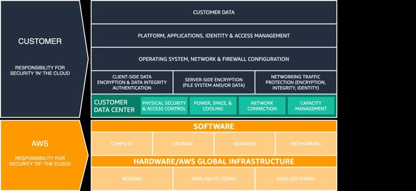
Amazon Web Services AWS Outposts High Availability Design and Architecture Considerations

Understanding the updated Shared
Responsibility Model
When you deploy AWS Outposts infrastructure into your data centers or co-location
facilities, you take on additional responsibilities in the AWS Shared Responsibility
model. For example, in the Region, AWS provides diverse power sources, redundant
core networking, and resilient Wide Area Network (WAN) connectivity to ensure
services are available in the event of one or more component failures.

With Outposts, you are responsible for providing resilient power and network
connectivity to the Outpost racks to meet your availability requirements for workloads
running on Outposts.

 AWS Shared Responsibility Model updated for AWS Outposts

With AWS Outposts, you are responsible for the physical security and access controls
of the data center environment. You must provide sufficient power, space, and cooling
to keep the Outpost operational and network connections to connect the Outpost back
to the Region.

Since Outpost capacity is finite and determined by the size and number of racks AWS
installs at your site, you must decide how much EC2, EBS, and S3 on Outposts
capacity you need to run your initial workloads, accommodate future growth, and to
provide extra capacity to mitigate server failures and maintenance events.

 5
Amazon Web Services AWS Outposts High Availability Design and Architecture Considerations

AWS is responsible for the availability of the Outposts infrastructure including the power
supplies, servers, and networking equipment within the AWS Outposts racks. AWS also
manages the virtualization hypervisor, storage systems, and the AWS services that run
on Outposts.

A central power shelf in each Outposts rack converts from AC to DC power and
supplies power to servers in the rack via a bus bar architecture. With the bus bar
architecture, half the power supplies in the rack can fail and all the servers will continue
to run uninterrupted.

 Figure 1 - AWS Outposts AC-to-DC power supplies and bus bar power distribution

The network switches and cabling within and between the Outposts racks are also fully
redundant. A fiber patch panel provides connectivity between an Outpost rack and the
on-premises network and serves as the demarcation point between the customer-
managed data center environment and the managed AWS Outposts environment.

Just like in the Region, AWS is responsible for the cloud services offered on Outposts
and takes on additional responsibilities as you select and deploy higher-level managed
services like Amazon RDS on Outposts. You should review the AWS Shared
Responsibility Model and the Frequently Asked Questions (FAQ) pages for individual
services as you consider and select services to deploy on Outposts. These resources
provide additional details on the division of responsibilities between you and AWS.

Thinking in terms of failure modes
When designing a highly available application or system you must consider what
components may fail, what impact component failures will have on the system, and
what mechanisms you can implement to mitigate or eliminate the impact of component
failures. Does your application run on a single server, in a single rack, or in a single data
center? What will happen when a server, rack, or data center experiences a temporary
or permanent failure? What happens when there is a failure in a critical sub-system like
networking or within the application itself? These are failure modes.

 6
Amazon Web Services AWS Outposts High Availability Design and Architecture Considerations

You should consider the failure modes in this section when planning your Outposts and
application deployments. The sections that follow will review how to mitigate these
failure modes to provide an increased level of high availability for your application
environment.

Failure mode 1: Network
An Outpost deployment depends on a resilient connection to its parent Region for
management and monitoring. Network disruptions may be caused by a variety of
failures such as operator errors, equipment failures, and service provider outages. An
Outpost is considered disconnected when it cannot communicate with the Region via
the Service Link.

Redundant network paths can help mitigate the risk of disconnect events. You should
map application dependencies and network traffic to understand the impact disconnect
events will have on workload operations. Plan sufficient network redundancy to meet
your application availability requirements.

During a disconnect event, instances running on an Outpost continue to run and are
accessible from on-premises networks through the Outpost Local Gateway (LGW).
Local workloads and services may be impaired or fail if they rely on services in the
Region. Mutating requests (like starting or stopping instances on the Outpost), control
plane operations, and service telemetry (e.g. CloudWatch metrics) will fail while the
Outpost is disconnected from the Region.

Failure mode 2: Instances
EC2 Instances may become impaired or fail if the server they are running on has an
issue or if the instance experiences an operating system or application failure. How
applications handle these types of failures depends on the application architecture.
Monolithic applications typically use application or system features for recovery while
modular service oriented or micro-services architectures typically replace failed
components to maintain service availability.

You can replace failed instances with new instances using automated mechanisms like
EC2 Auto Scaling groups. Instance auto recovery can restart instances that fail due to
server failures provided there is sufficient spare capacity available on the remaining
servers.

 7
Amazon Web Services AWS Outposts High Availability Design and Architecture Considerations

Failure mode 3: Compute and storage servers
Servers can fail or become impaired and may need to be taken out of operation
(temporarily or permanently) for a variety of reasons, such as component failures and
scheduled maintenance operations. How services on Outposts handle server failures
and impairments varies and can depend on how customers configure high availability
options.

You should order sufficient compute capacity to support an N+M availability model,
where N is the required capacity and M is the spare capacity provisioned to
accommodate server failures.

Hardware replacements for failed servers are provided as part of the fully managed
AWS Outposts service. AWS actively monitors the health of all servers and networking
devices in an Outpost deployment. If there is a need to perform physical maintenance,
AWS will schedule a time to visit your site to replace failed components. Provisioning
spare capacity allows you to keep your workloads running while failed servers are taken
out of service and replaced.

Failure mode 4: Racks or data centers
Rack failures may occur due to a total loss of power to racks or due to environmental
failures like loss of cooling or physical damage to the data center from a flood or
earthquake. Deficiencies in data center power distribution architectures or errors during
standard data center power maintenance can result in loss of power to one or more
racks or even the entire data center.

These scenarios can be mitigated by deploying infrastructure to multiple data center
floors or locations that are independent from one another within the same campus or
metro area.

Taking this approach with AWS Outposts will require careful consideration for how
applications are architected and distributed to run across multiple separate logical
Outposts to maintain application availability.

Failure mode 5: AWS Availability Zone or Region
Each Outpost is anchored to a specific Availability Zone (AZ) within an AWS Region.
Failures within the anchor AZ or parent Region could cause the loss of Outpost
management and mutability and may disrupt network communication between the
Outpost and the Region.

 8
Amazon Web Services AWS Outposts High Availability Design and Architecture Considerations

Similar to network failures, AZ or Region failures may cause the Outpost to become
disconnected from the Region. The instances running on an Outpost continue to run
and are accessible from on-premises networks through the Outpost Local Gateway
(LGW) and may be impaired or fail if they rely on services in the Region, as described
previously.

To mitigate the impact of AWS AZ and Region failures, you can deploy multiple
Outposts each anchored to a different AZ or Region. You may then design your
workload to operate in a distributed multi-Outpost deployment model using many of the
similar mechanisms and architectural patterns that you use to design and deploy on
AWS today.

Building HA applications and infrastructure
solutions with AWS Outposts
With AWS Outposts, you can build, manage, and scale highly available on-premises
applications using familiar AWS cloud services and tools. It's important to understand
cloud HA architectures and approaches are generally different from traditional on-
premises HA architectures you may be running in your datacenter today.

With traditional on-premises HA application deployments, applications are deployed in
virtual machines (VMs). Complex IT systems and infrastructure are deployed and
maintained to keep those virtual machines running and healthy. The VMs often have
specific identities and each VM may play a critical role in the total application
architecture.

Architectural roles are tightly coupled to VM identities. Systems architects leverage IT
infrastructure features to provide highly available VM runtime environments that provide
each VM with reliable access to compute capacity, storage volumes, and network
services. If a VM fails, automated or manual recovery processes are run to restore the
failed VM to a healthy state, often on other infrastructure or in another datacenter
entirely.

Cloud HA architectures take a different approach. AWS cloud services provide reliable
compute, storage, and networking capabilities. Application components are deployed to
EC2 instances, containers, serverless functions, or other managed services.

An instance is an instantiation of an application component – perhaps one of many
performing that role. Application components are loosely coupled to one another and to
the role they play in the total application architecture. The individual identity of an

 9
Amazon Web Services AWS Outposts High Availability Design and Architecture Considerations

instance is generally not important. Additional instances may be created or destroyed to
scale up or scale down in response to demand. Failed instances or unhealthy instances
are simply replaced with new healthy instances.

AWS Outposts is a fully managed service that extends AWS compute, storage,
networking, database, and other cloud services to on-premises locations for a truly
consistent hybrid experience. You should not think of the Outposts service as a drop-in
replacement for IT infrastructure systems with traditional on-premises HA mechanisms.
Attempting to use AWS services and Outposts to support a traditional on-premises HA
architecture is an anti-pattern.

Workloads running on AWS Outposts use cloud HA mechanisms like Amazon EC2 Auto
Scaling (to scale horizontally to meet workload demands), EC2 health checks (to detect
and remove unhealthy instances), and Application Load Balancers (to redirect incoming
workload traffic to scaled or replaced instances). When migrating applications to the
cloud, whether to an AWS Region or AWS Outposts, you should update your HA
application architecture to begin taking advantage of managed cloud services and cloud
HA mechanisms.

The following sections introduce architecture patterns, anti-patterns, and recommended
practices for deploying AWS Outposts in your on-premises environments to run
workloads with high availability requirements. These sections introduce patterns and
practices; however, they do not provide configuration and implementation details. You
should read and become familiar with the AWS Outposts FAQs and User Guide and the
FAQs and service documentation for the services that run on Outposts as you prepare
your environment for Outposts and your applications for migration to AWS services.

Networking
An Outpost deployment depends on a resilient connection to its anchor AZ for
management, monitoring, and service operations to function properly. You should
provision your on-premises network to provide redundant network connections for each
Outpost rack and reliable connectivity back to the anchor points in the AWS cloud. Also
consider network paths between the application workloads running on the Outpost and
the other on-premises and cloud systems they communicate with – how will you route
this traffic in your network?

Network attachment
Each AWS Outposts rack is configured with redundant top-of-rack switches called
Outpost Networking Devices (ONDs). The compute and storage servers in each rack

 10
Amazon Web Services AWS Outposts High Availability Design and Architecture Considerations

connect to both ONDs. You should connect each OND to a separate switch called a
Customer Networking Device (CND) in your data center to provide diverse physical and
logical paths for each Outpost rack. ONDs connect to your CNDs with one or more
physical connections using fiber optic cables and optical transceivers. The physical
connections are configured in logical link aggregation group (LAG) links.

 Multi-rack Outpost with redundant network attachments

The OND to CND links are always configured in a LAG – even if the physical connection
is a single fiber optic cable. Configuring the links as LAG groups allow you to increase
the link bandwidth by adding additional physical connections to the logical group. The
LAG links are configured as IEEE 802.1q ethernet trunks to enable segregated
networking between the Outpost and the on-premises network.

Every Outpost has at least two logically segregated networks that need to communicate
with or across the customer network:

 1. Service Link network – allocates Service Link IP addresses to the Outpost
 servers and facilitates communication with the on-premises network to allow the
 servers to connect back to the Outpost anchor points in the Region.

 11
Amazon Web Services AWS Outposts High Availability Design and Architecture Considerations

 2. Local Gateway network – enables communication between the VPC subnets
 on the Outpost and the on-premises network via the Outpost Local Gateway
 (LGW).
These segregated networks attach to the on-premises network by a set of point-to-point
IP connections over the LAG links. Each OND to CND LAG link is configured with VLAN
IDs, point-to-point (/30 or /31) IP subnets, and eBGP peering for each segregated
network (Service Link and LGW). You should consider the LAG links, with their point-to-
point VLANs and subnets, as layer-2 segmented, routed layer-3 connections. The
routed IP connections provide redundant logical paths that facilitate communication
between the segregated networks on the Outpost and the on-premises network.

 Service Link peering

 12
Amazon Web Services AWS Outposts High Availability Design and Architecture Considerations

 Local Gateway peering

You should terminate the layer-2 LAG links (and their VLANs) on the directly attached
CND switches and configure the IP interfaces and BGP peering on the CND switches.
You should not bridge the LAG VLANs between your data center switches. For more
information, see Network layer connectivity in the AWS Outposts User Guide.

Inside a logical multi-rack Outpost, the ONDs are redundantly interconnected to provide
highly available network connectivity between the racks and the workloads running on
the servers. AWS is responsible for network availability within the Outpost.

Recommended practices for highly available network attachment:
 • Connect each Outpost Networking Device (OND) in an Outpost rack to a
 separate Customer Networking Device (CND) in the data center.

 • Terminate the layer-2 links, VLANs, layer-3 IP subnets, and BGP peering on the
 directly attached Customer Networking Device (CND) switches. Do not bridge the
 OND to CND VLANs between the CNDs or across the on-premises network.

 • Add links to the Link Aggregation Groups (LAGs) to increase the available
 bandwidth between the Outpost and the data center. Do not rely on the
 aggregate bandwidth of the diverse paths through both ONDs.

 13
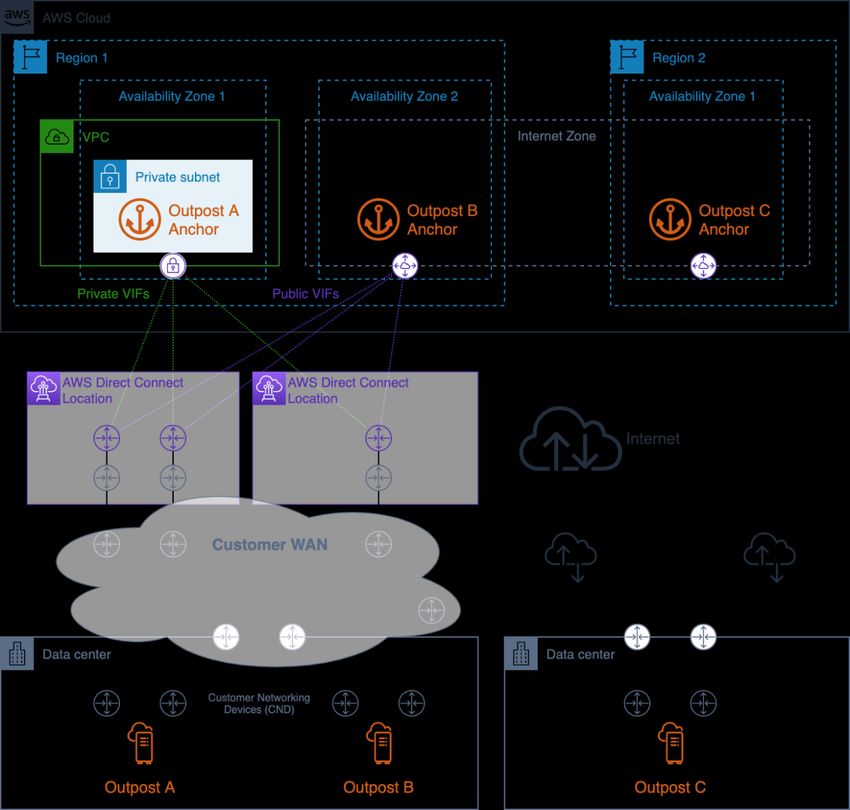
Amazon Web Services AWS Outposts High Availability Design and Architecture Considerations

 • Use the diverse paths through the redundant ONDs to provide resilient
 connectivity between the Outpost networks and the on-premises network.

Anchor connectivity
An Outpost Service Link connects to either public or private anchors (not both) in a
specific Availability Zone (AZ) in the Outpost’s parent Region. Outpost servers initiate
outbound Service Link VPN connections from their Service Link IP addresses to the
anchor points in the anchor AZ. These connections use UDP and TCP port 443. AWS is
responsible for the availability of the anchor points in the Region.

You must ensure the Outpost Service Link IP addresses can connect through your
network to the anchor points in the anchor AZ. The Service Link IP addresses do not
need to communicate with other hosts on your on-premises network.

Public anchor points reside in the Region’s public IP ranges (in the EC2 service CIDR
blocks) and may be accessed via the internet or AWS Direct Connect (DX) public virtual
interfaces (VIFs). The use of public anchor points allows for more flexible path selection
as Service Link traffic may be routed over any available path that can successfully
reach the anchor points on the public internet.

Private anchor points allow you to use your IP address ranges for anchor connectivity.
Private anchor points are created in a private subnet within a dedicated VPC using
customer-assigned IP addresses. The VPC is created in the AWS account that owns
the Outpost resource and you are responsible for ensuring the VPC is available and
properly configured (don’t delete it!). Private anchor points must be accessed using
Direct Connect private VIFs.

You should provision redundant network paths between the Outpost and the anchor
points in the Region with connections terminating on separate devices in more than one
location. Dynamic routing should be configured to automatically reroute traffic to
alternate paths when connections or networking devices fail. You should provision
sufficient network capacity to ensure that the failure of one WAN path does not
overwhelm the remaining paths.

The following diagram shows three Outposts with redundant network paths to their
anchor AZs using AWS Direct Connect as well as public internet connectivity. Outpost A
and Outpost B are anchored to different Availability Zones in the same Region. Outpost
A connects to private anchor points in AZ 1 of region 1. Outpost B connects to public
anchor points in AZ 2 of region 1. Outpost C connects to public anchors in AZ 1 of
region 2.

 14
Amazon Web Services AWS Outposts High Availability Design and Architecture Considerations

 Highly available anchor connectivity with AWS Direct Connect and public internet access

Outpost A has three redundant network paths to reach its private anchor point. Two
paths are available through redundant Direct Connect circuits at a single Direct Connect
location. The third path is available through a Direct Connect circuit at a second Direct
Connect location. This design keeps Outpost A’s Service Link traffic on private networks
and provides path redundancy that allows for failure of any one of the Direct Connect
circuits or failure of an entire Direct Connect location.

Outpost B has four redundant network paths to reach its public anchor point. Three
paths are available through public VIFs provisioned on the Direct Connect circuits and

 15
Amazon Web Services AWS Outposts High Availability Design and Architecture Considerations

locations used by Outpost A. The fourth path is available through the customer WAN
and the public internet. Outpost B’s Service Link traffic may be routed over any
available path that can successfully reach the anchor points on the public internet.
Using the Direct Connect paths may provide more consistent latency and higher
bandwidth availability, while the public internet path may be used for Disaster Recovery
(DR) or bandwidth augmentation scenarios.

Outpost C has two redundant network paths to reach its public anchor point. Outpost C
is deployed in a different data center than Outposts A and B. Outpost C’s data center
does not have dedicated circuits connecting to the customer WAN. Instead, the data
center has redundant internet connections provided by two different Internet Service
Providers (ISPs). Outpost C’s Service Link traffic may be routed over either of the ISP
networks to reach the anchor points on the public internet. This design allows flexibility
to route Service Link traffic over any available public internet connection. However, the
end-to-end path is dependent on public third-party networks where bandwidth
availability and network latency fluctuate.

The network path between an Outpost and its Service Link anchor points must meet the
following bandwidth and latency specifications:

 • 500 Mbps - 1 Gbps of available bandwidth per Outpost rack
 (e.g. 3 racks: 1.5 – 3 Gbps available bandwidth)

 • Less than 300 milliseconds (round-trip) latency

Recommended practices for highly available anchor connectivity:
 • Provision redundant network paths between each Outpost and its anchor points
 in the Region.

 • Use Direct Connect (DX) paths to control latency and bandwidth availability.
 • Ensure that TCP and UDP port 443 are open (outbound) from the Outpost
 Service Link CIDR blocks to the EC2 IP address ranges in the parent Region.
 Ensure the ports are open on all network paths.

 • Ensure each path meets the bandwidth availability and latency requirements.

 • Use dynamic routing to automate traffic redirection around network failures.

 • Test routing the Service Link traffic over each planned network path to ensure
 the path functions as expected.

 16
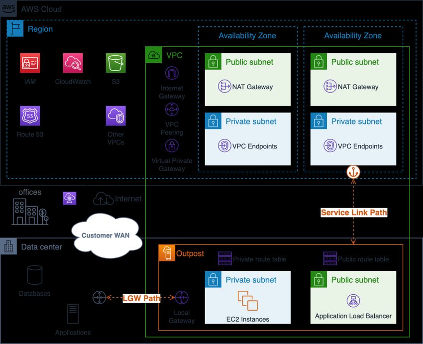
Amazon Web Services AWS Outposts High Availability Design and Architecture Considerations

Application/workload routing
There are two paths out of the Outpost for application workloads:

 1. The Service Link path

 2. The Local Gateway (LGW) path

You configure the Outpost subnet route tables to control which path to take to reach
destination networks. Routes pointed to the LGW will direct traffic out the Local
Gateway and to the on-premises network. Routes pointed to targets in the Region like
Internet Gateways, NAT Gateways, Virtual Private Gateways, and VPC peering
connections will direct traffic across the Service Link to reach these targets.

 Visualization of the Outpost Service Link and LGW network paths

 17
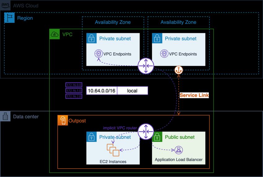
Amazon Web Services AWS Outposts High Availability Design and Architecture Considerations

You should take care when planning application routing to consider both normal
operation and limited routing and service availability during network failures. The
Service Link path is not available when an Outpost is disconnected from the Region.

You should provision diverse paths and configure dynamic routing between the Outpost
LGW and your critical on-premises applications, systems and users. Redundant
network paths allow the network to route traffic around failures and ensure that on-
premises resources will be able to communicate with workloads running on the Outpost
during partial network failures.

Outpost VPC route configurations are static. You configure subnet routing tables
through the AWS Console, CLI, APIs, and other Infrastructure as Code (IaC) tools;
however, you will not be able modify the subnet routing tables during a disconnect
event. You will have to reestablish connectivity between the Outpost and the Region to
update the route tables. Use the same routes for normal operations as you plan to use
during disconnect events.

Resources on the Outpost can reach the internet via the Service Link and an Internet
Gateway (IGW) in the Region or via the Local Gateway (LGW) path. Routing internet
traffic over the LGW path and the on-premises network allows you to use existing on-
premises internet ingress/egress points and may provide lower latency, higher MTUs,
and reduced AWS data egress charges when compared to using the Service Link path
to an IGW in the Region.

If your application must run on-premises and it needs to be accessible from the public
internet, you should route the application traffic over your on-premises internet
connection(s) to the LGW to reach the resources on the Outpost.

While you can configure subnets on an Outpost like public subnets in the Region, this
may be an undesirable practice for most use cases. Inbound internet traffic will come in
through the AWS Region and be routed over the Service Link to the resources running
on the Outpost.

The response traffic will in turn be routed over the Service Link and back out through
the AWS Region’s internet connections. This traffic pattern may add latency and will
incur data egress charges as traffic leaves the Region on its way to the Outpost and as
return traffic comes back through the Region and egresses out to the internet. If your
application can run in the Region, the Region is the best place to run it.

Traffic between VPC resources (in the same VPC) will always follow the local VPC
CIDR route and be routed between subnets by the implicit VPC routers.

 18
Amazon Web Services AWS Outposts High Availability Design and Architecture Considerations

For example, traffic between an EC2 instance running on the Outpost and a VPC
Endpoint in the Region will always be routed over the Service Link.

 Local VPC routing through the implicit routers

Recommended practices for application/workload routing:
 • Use the Local Gateway (LGW) path instead of the Service Link path where
 possible.
 • Route internet traffic over the LGW path.

 • Configure the Outpost subnet routing tables with a standard set of routes – they
 will be used for both normal operations and during disconnect events.

 • Provision redundant network paths between the Outpost LGW and critical on-
 premises application resources. Use dynamic routing to automate traffic
 redirection around on-premises network failures.

 19
Amazon Web Services AWS Outposts High Availability Design and Architecture Considerations

Compute
Capacity planning
While EC2 capacity in AWS Regions is seemingly infinite, capacity on Outposts is finite
– constrained by the total volume of compute capacity ordered. You are responsible for
planning and managing the compute capacity of your Outposts deployments. You
should order sufficient compute capacity to support an N+M availability model, where N
is the required number of servers and M is the number of spare servers provisioned to
accommodate server failures. N+1 and N+2 are the most common availability levels.

Each server (C5, M5, R5, etc.) supports a single family of EC2 instances. Before you
can launch instances on EC2 compute servers, you must provide slotting layouts that
specify the EC2 instance sizes you want each server to provide. AWS configures each
server with the requested slotting layout.

Servers may be homogeneously slotted where all slots are the same instance size (e.g.,
48 m5.large slots) or heterogeneously slotted with a mixture of instances types (e.g., 4
m5.large, 4 m5.xlarge, 3 m5.2xlarge, 1 m5.4xlarge, and 1 m5.8xlarge) – see the next
three figures for visualizations of these slotting configurations.

 m5.24xlarge server compute resources

 m5.24xlarge server homogenously slotted into 48 m5.large slots

 20
Amazon Web Services AWS Outposts High Availability Design and Architecture Considerations

 m5.24xlarge server heterogeneously slotted into 4 m5.large, 4 m5.xlarge, 3 m5.2xlarge, 1
 m5.4xlarge, and 1 m5.8xlarge slots

The full server capacity does not have to be slotted. Slots may be added to a server that
has available unallocated capacity. You modify a slotting layout by opening a support
ticket. Enterprise Support may require you to shut down or restart certain instances to
complete a reslotting request if the new slotting layout cannot be applied while certain
slots are occupied by running instances.

All servers contribute their provisioned slots to the EC2 capacity pools on the Outpost,
and all slots of a given instance type and size are managed as a single EC2 capacity
pool. For example, the previous heterogeneously slotted server with m5.large,
m5.xlarge, m5.2xlarge, m5.4xlarge, and m5.8xlarge slots would contribute these slots to
five EC2 capacity pools – one pool for each instance type and size.

It is important to consider server slotting and EC2 capacity pools when planning spare
capacity for N+M server availability. AWS detects when a server fails or is degraded
and schedules a site visit to replace the failed server. You should design your EC2
capacity pools to tolerate the failure of at least one server of each instance family (N+1)
in an Outpost. With this minimum level of server availability, when a server fails or
needs to be taken out of service, you can restart failed or degraded instances on the
spare slots of the remaining servers of the same family.

Planning for N+M availability is simple when you have homogenously slotted servers or
groups of heterogeneously slotted servers with identical slotting layouts. You simply
calculate the number of servers (N) your need to run all your workloads and then add
(M) additional servers to meet your requirements for server availability during failure and
maintenance events.

In the following figure, four m5.24xlarge servers are heterogeneously slotted with an
identical slotting layout. The four servers create five EC2 capacity pools. Each pool is
running at maximum utilization (75%) to maintain N+1 availability for the instances
running on these four servers. If any server fails, there is sufficient room to restart the
failed instances on the remaining servers.

 21
Amazon Web Services AWS Outposts High Availability Design and Architecture Considerations

 Visualization of EC2 server slots, running instances, and slot pools

For more complex slotting layouts, where servers are not identically slotted, you will
need to calculate N+M availability for each EC2 capacity pool. You can use the
following formula to calculate how many servers (that contribute slots to a given EC2
capacity pool) can fail and still allow the remaining servers to carry the running
instances:

 =[ ]

Where:

 • poolSlotsavailable is the number of available slots in the given EC2 capacity pool
 (total number of slots in the pool minus the number of running instances)

 • serverSlotsmax is the maximum number of slots contributed by any server to the
 given EC2 capacity pool

 • M is the number of servers that can fail and still allow the remaining servers to
 carry the running instances

Example: An Outpost has three servers that contribute slots to an m5.2xlarge capacity
pool. The first contributes 4 slots, the second contributes 3 slots, and the third server
contributes 2 slots. The m5.2xlarge instance pool on the Outpost has a total capacity of
9 slots (4 + 3 + 2). The Outpost has 4 running m5.2xlarge instances. How many servers
may fail and still allow the remaining servers to carry the running instances?

 22
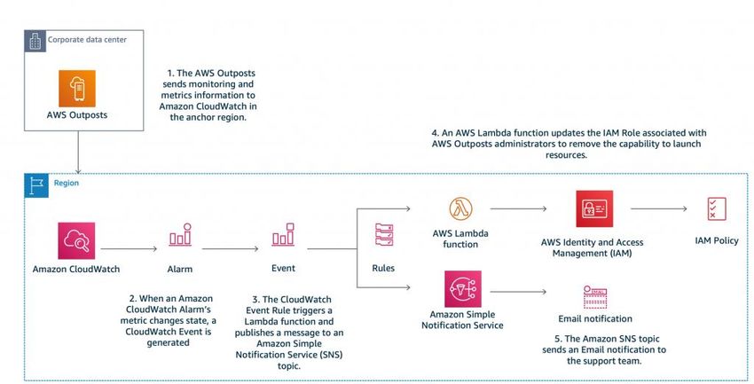
Amazon Web Services AWS Outposts High Availability Design and Architecture Considerations

 = − = 9 − 4 = 5

 = max([4, 3, 2]) = 4

 5
 = [ ] = [ ] = [1.25] = 1
 4

Answer: You can lose any 1 of the servers and still carry the running instances on the
remaining servers.

Recommended practices for compute capacity planning:
 • Size your compute capacity to provide N+M redundancy for each EC2 capacity
 pool on an Outpost.

 o Deploy N+M servers for homogenously or identical heterogeneously slotted
 servers.

 o Calculate the N+M availability for each EC2 capacity pool and ensure that
 each pool meets your availability requirements.

Capacity management
You can monitor Outpost EC2 instance pool utilization in the AWS Console and via
Amazon CloudWatch metrics. Contact Enterprise Support to retrieve or change the
slotting layouts for your Outposts.

You use the same instance auto recovery and EC2 Auto Scaling mechanisms to
recover or replace instances impacted by server failures and maintenance events. You
must monitor and manage your Outpost capacity to ensure sufficient spare capacity is
always available to accommodate server failures. The Managing your AWS Outposts
capacity using Amazon CloudWatch and AWS Lambda blog post provides a hands-on
tutorial showing you how to combine AWS CloudWatch and AWS Lambda to manage
your Outpost capacity to maintain instance availability.

 23
Amazon Web Services AWS Outposts High Availability Design and Architecture Considerations

 Managing AWS Outposts capacity with Amazon CloudWatch and AWS Lambda

Recommended practices for compute capacity management:
 • Configure your EC2 instances in Auto Scaling groups or use instance auto
 recovery to restart failed instances.

 • Automate capacity monitoring for your Outpost deployments and configure
 notifications and (optionally) automated responses for capacity alarms.

Instance placement
Outposts have a finite number of compute servers. If your application deploys multiple
related instances on Outposts; without additional configuration, the instances may
deploy on the same server or on servers in the same rack. Today, there are three
mechanisms you may use to distribute instances to mitigate the risk of running related
instances on the same infrastructure:

Multi-Outpost deployment – similar to a multi-AZ strategy in the Region, you can
deploy Outposts to separate data centers and deploy application resources to specific
Outposts. This allows you to run instances on the desired Outpost (a logical set of
racks). A multi-Outpost strategy may be employed to protect against rack and data
center failure modes and, if the Outposts are anchored to separate AZs or Regions,
may also provide protection against AZ or Region failure modes. For more information
about multi-Outpost architectures, see the Larger Failure Modes.

 24
Amazon Web Services AWS Outposts High Availability Design and Architecture Considerations

Amazon EC2 placement groups on Outposts (single-Outpost multi-rack instance
placement) – allow you to use the cluster, spread, and partition strategies to influence
placement. The spread and partition placement strategies allow you distribute instances
across racks in a multi-rack Outpost.

A spread placement group provides a simple way distribute single instances across
racks to reduce the potential for correlated failures. You may only deploy into the group
as many instances as you have racks in your Outpost.

 EC2 spread placement group on an Outpost with three racks

You can also distribute instances across multiple racks with partition placement groups.
Use automatic distribution to spread instances across partitions in the group or deploy
instances to selected target partitions. Deploying instances to target partitions allows
you to deploy selected resources to the same rack while distributing other resources
across racks. For example, if you have a logical Outpost with three racks, creating a
partition placement group with three partitions allows you to distribute resources across
the racks.

 25
Amazon Web Services AWS Outposts High Availability Design and Architecture Considerations

 EC2 partition placement groups on an Outpost with three racks

Creative server slotting – if you have a single-rack Outpost or if the service you are
using on Outposts does not support placement groups, you may be able to use creative
slotting to ensure your instances do not deploy on the same physical server. If the
related instances are the same EC2 instance size, you may be able to slot your servers
to limit the number of slots of that size configured on each server – spreading the slots
across the servers. Server slotting will limit the number of instances (of that size) that
can run on a single server.

As an example, consider the slotting layout shown previously in Figure 13. If your
application needed to deploy three m5.4xlarge instances on the Outpost configured with
this slotting layout, EC2 would place each instance on a separate server and there
would be no possibility that these instances could run on the same server – as long as
the slotting configuration does not change to open additional m5.4xlarge slots on the
servers.

Recommended practices for compute instance placement:
 • Use Amazon EC2 placement groups on Outposts to control placement of
 instances across racks within a single Outpost.

 • Instead of ordering an Outpost with a single medium or large Outpost rack,
 consider splitting the capacity into two small or medium racks to allow you to take
 advantage of the EC2 placement groups ability to distribute instances across
 racks.

 26
Amazon Web Services AWS Outposts High Availability Design and Architecture Considerations

Storage
The AWS Outposts service provides three storage types:

 1. Instance storage on supported EC2 instance types
 2. Amazon Elastic Block Store (EBS) gp2 volumes for persistent block storage
 3. Amazon Simple Storage Service on Outposts (S3 on Outposts) for local
 object storage
Instance storage is provided on supported servers (C5d, M5d, R5d, G4dn, and I3en).
Just like in the Region the data in an instance store persists only for the (running)
lifetime of the instance.

Outposts EBS volumes and S3 on Outposts object storage are provided as part of the
AWS Outposts managed service. Customers are responsible for capacity management
of the Outpost storage pools. Customers specify their storage requirements for EBS and
S3 storage when ordering an Outpost. AWS configures the Outpost with the number of
storage servers required to provide the requested storage capacity. AWS is responsible
for the availability of the EBS and S3 on Outposts storage services. Sufficient storage
servers are provisioned to provide highly available storage services to the Outpost. Loss
of a single storage server should not disrupt the services nor result in data loss.

You can use the AWS Console and CloudWatch metrics to monitor Outpost EBS and
S3 on Outposts capacity utilization.

Data protection
For EBS Volumes: AWS Outposts support EBS volume snapshots to provide a simple
and secure data protection mechanism to protect your block storage data. Snapshots
are point-in-time incremental backups of your EBS volumes. By default, snapshots of
Amazon EBS volumes on your Outpost are stored on Amazon S3 in the Region. If your
Outposts have been configured with S3 on Outposts capacity, you can use EBS Local
Snapshots on Outposts to store snapshots locally on your Outpost using S3 on
Outposts storage.

For S3 on Outposts buckets: You can use AWS DataSync to automate S3 on Outposts
data transfers between your Outpost and the Region. DataSync allows you to choose
what to transfer, when to transfer, and how much bandwidth to use. Backing up your on-
premises S3 on Outposts buckets to S3 buckets in the Region allows you to leverage
the 99.999999999% (11 9's) of data durability and additional storage tiers (Standard,

 27
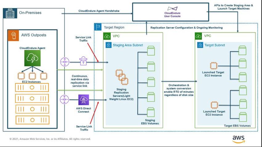
Amazon Web Services AWS Outposts High Availability Design and Architecture Considerations

Infrequent Access, and Glacier) for cost optimization available with the regional S3
service.

Instance replication: You can use CloudEndure to replicate individual instances from on-
premises systems to an Outpost, from an Outpost to the Region, from the Region to an
Outpost, or from one Outpost to another. The Architecting for DR on AWS Outposts with
CloudEndure blog post describes each of these scenarios and how to design a solution
with CloudEndure.

 Disaster recovery from an Outpost to the Region

Using AWS Outposts as a CloudEndure destination (replication target) requires S3 on
Outposts storage.

Recommended practices for data protection:
 • Use EBS snapshots to create point-in-time backups of block storage volumes to
 S3 in the Region or S3 on Outposts.

 • Use AWS DataSync to backup objects stored in S3 on Outpost to S3 in the
 Region.

 • Use CloudEndure to replicate instances between on-premises systems, logical
 Outposts, and the Region.

 28
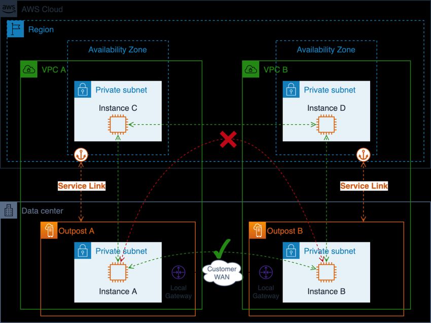
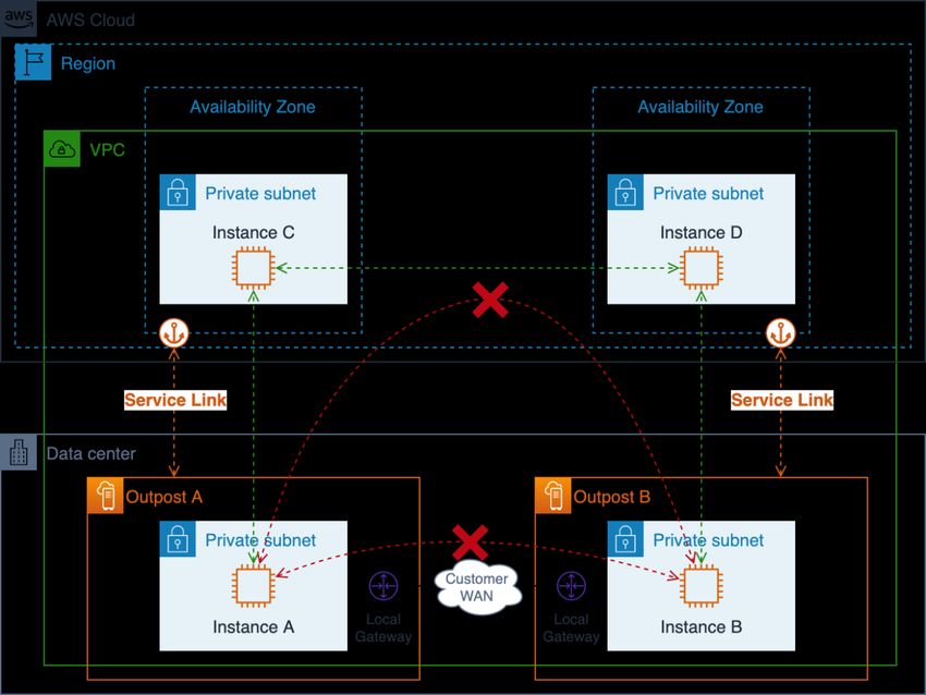
Amazon Web Services AWS Outposts High Availability Design and Architecture Considerations

Larger Failure Modes
To design HA architectures to mitigate larger failure modes like rack, data center,
Availability Zone (AZ), or Region failures, you should deploy multiple Outposts with
sufficient infrastructure capacity in separate data centers with independent power and
WAN connectivity. You anchor the Outposts to different Availability Zones (AZs) within
an AWS Region or across multiple Regions. You should also provision resilient and
sufficient site-to-site connectivity between the locations to support synchronous or
asynchronous data replication and workload traffic redirection. Depending on your
application architecture, you can use globally available Amazon Route 53 DNS and
regionally available Elastic Load Balancing services to direct traffic to the desired
location and automate traffic redirection to surviving locations in the event of large-scale
failures.

There are networking limitations that you should be aware of when designing and
deploying application workloads across multiple Outposts. Resources on two separate
Outposts cannot communicate with each other by transiting traffic through the Region.
Resources on two separate Outposts deployed within the same VPC cannot
communicate with each other across the customer network. Resources on two separate
Outposts deployed in different VPCs can communicate with each other across the
customer network.

The following two figures illustrate the blocked and successful network paths.

 29
Amazon Web Services AWS Outposts High Availability Design and Architecture Considerations

 Single VPC multiple-outpost network paths

Outpost-to-Outpost traffic transiting the Region is blocked as this is an anti-pattern.
Such traffic would incur egress charges in both directions and likely have much higher
latency than simply routing the traffic across the Customer WAN.

Resources on multiple Outposts in the same VPC cannot communicate with each other.
The traffic between Outpost in the same VPC will always follow the local VPC CIDR
route through the Region where it will be blocked.

You should use separate VPCs to deploy resources on multiple Outposts to allow you to
route Outpost-to-Outpost traffic across your local on-premises and WAN networks.

 30
Amazon Web Services AWS Outposts High Availability Design and Architecture Considerations

 Multiple-VPC multiple-Outpost network paths

Recommended practices for protecting against larger failure modes:

 • Deploy multiple Outposts anchored to multiple AZs and Regions.

 • Use separate VPCs for each Outpost in a multi-Outpost deployment.

Conclusion
With AWS Outposts, you can build, manage, and scale highly available on-premises
applications using familiar AWS tools and services like Amazon EC2, Amazon EBS,
Amazon S3 on Outposts, Amazon ECS, Amazon EKS, and Amazon RDS. Workloads
can run locally, serve clients, access applications and systems in your on-premises
networks, and access the full set of services in the AWS Region. Outposts are ideal for
workloads that require low latency access to on-premises systems, local data

 31
Amazon Web Services AWS Outposts High Availability Design and Architecture Considerations

processing, data residency, and migration of applications with local system
interdependencies.

When you provide an Outpost deployment with adequate power, space, and cooling
and resilient connections to the AWS Region, you can build highly available single data
center services. And, for higher levels of availability and resiliency, you can deploy
multiple Outposts and distribute your applications across logical and geographic
boundaries.

Outposts remove the undifferentiated heavy lifting of building on-premises compute,
storage, and application networking pools and allow you to extend the reach of the AWS
Global Infrastructure to your data centers and co-location facilities. Now, you can focus
your time and energy towards modernizing your applications, streamlining your
application deployments, and increasing the business impact of your IT services.

Contributors
Contributors to this document include:

 • Chris Lunsford, Senior Specialist Solutions Architect, AWS Outposts

 • Rohan Mathews, Lead Architect, AWS Outposts

Document revisions
 Date Description
 August 12, 2021 First publication

 32
You can also read