BARCELONA Smart Drone Challenge 2019 - Competition Rules
←
→
Page content transcription
If your browser does not render page correctly, please read the page content below
Issue 12 – 2018/19

                 BARCELONA
Smart Drone Challenge 2019
                  Competition Rules

Mission and Competition Rules Issue 12, September 2018

        © - Sharing passion for flying -                     1
Issue 12 – 2018/19

Contents

  1. Introduction ............................................................................…..............….........… 5
  2. Competition Overview ...........................................................…..........................… 8
  3. Design and Operational Requirements .........................…...............................… 13
  4. Statement of Work ............................................................................…..............… 19
  5. Adjudication and Scoring Criteria ..........…........................................................… 25
  6. Prizes and Awards …….......................................................................…..............… 28

      Annex A - Mission ..................................................................................…..........… 29
      Annex B - GPS Tracker Installation and Operation .........……..............…............ 35
      Annex C - General Guidance for Teams …...........................................…..........… 37
      Annex D - Document Templates and Guidance ...............…...............…..........… 38
      Annex E - Guidance on Autopilot Selection .....................…................…..….....… 44

                    © - Sharing passion for flying -                                                                         2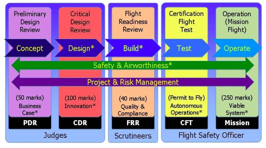
Issue 12 – 2018/19

Glossary and Abbreviations

      AESA    State Air Safety Agency
      AGL     Above Ground Level
      BMFA    British Model Flying Association
      BRS     Ballistic Recovery Systems
      BSDC    Barcelona Smart Drone Challenge
      BVLOS   Beyond Visual Line of Sight
      CAA     Civil Aviation Authority
      CAT     Catalonia
      CDR     Critical Design Review
      COTS    Commercial Off The Shelf
      EU      European Union
      FMC     Flight Management Computer
      FRR     Flight Readiness Review
      FSO     Flight Safety Officer
      FTS     Flight Termination System
      FW      Fixed Wing
      GCS     Ground Control Station
      GPS     Global Positioning System
      KIAS    Knots: Indicated Air Speed
      MTOM    Maximum Take-Off Mass
      PDR     Preliminary Design Review
      PPE     Personal Protective Equipment
      QFE     Q-Code Field Elevation - Altimeter zeroed at runway height
      RW      Rotary Wing
      UA      Unmanned Aircraft
      UAS     Unmanned Aircraft System(s)
      VFR     Visual Flight Rules
      VLOS    Visual Line of Sight
      WP      Waypoint

              © - Sharing passion for flying -                                             3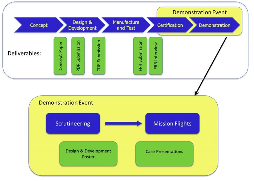
Issue 12 – 2018/19

Competition Rules – Revision status

     Issue 1, June 2015: Issued to Teams at the start of the 2015 competition

     Issue 2, July 2015: incorporates responses to feedback and questions, including:

         •   Clarification on use and pricing of COTS items;

         •   Definition of the height of the alphanumeric code in the target area;

         •   Details of the supplied GPS Tracker;

         •   Clarification on the target Mission time;

         •   Clarification on automatic take-off and use of launch / recovery equipment;

         •   Additional details provided on Flight Termination System functionality;

         •   Clarification on dropping two payloads in the same sortie;

         •   Clarification on measurement of payload drop accuracy;

         •   Clarification on allowable means of protecting the payload;

         •   Confirmation that UA is not permitted to land whilst deploying the payload;

         •   Piloting competency requirements added.

     Issue 3, March 2016: update to the example demonstration course and airfield map, Figures A2,
     A3.

     Issue 4, April 2016: Extensively revised to incorporate feedback from the 2016 competition, and
     issued to Teams at the launch of the 2016 competition.

     Issue 5, June 2016: incorporates responses to feedback and questions by UPC (Castelldefels).

     Issue 6, June 2016: confirmation of demonstration event dates (29 Jun – 2 Jul 2016) in the
     “Circuit of Catalonia”.

     Issue 7, June 2016: Demo ….

     Issue 8, December 2016: Small changes of date and adjustment of clearer words.

     Issue 9, January 2017: Change in the logo of BSDC, place the word "Barcelona".

     Issue 10, August 2017: Presentation of new Challenge 2017-18.

     Issue 12, September 2018: To streamline the logistics of the demonstration and allow more
     teams to participate, we review the procedures. The score of the mission is simplified to help
     the judges. Creation of a new headline. Restriction in the electrical system voltage to 4S to limit
     the individual power of the motor. Clarifications and guidelines on the execution of the
     demonstration part. Review of the preparation time of the flight line to 5 minutes (it was 2
     minutes). Review the score to reflect the only mission. A brief Preliminary Design Review (PDR)
     has been reintroduced....

                 © - Sharing passion for flying -                                                      4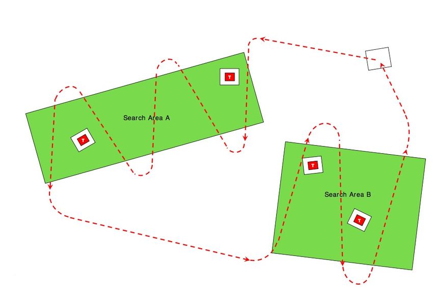
Issue 12 – 2018/19
1 Introduction
1.1 Competition Overview
The challenge will engage University and Middle or Higher Cycle Schools undergraduate teams
in the design, construction, development and demonstration of an Autonomous Unmanned
Aircraft System (UAS). With a Maximum Take-off Mass (MTOM) of under 7 kg, and operating
within Visual Line of Sight (VLOS), the Unmanned Aircraft (UA) will be we are detecting over
time a natural disaster.
The system will be required to work automatically, performing a series of tasks such as area
search, navigation of waypoints, capture of data and photographs of the area and return to the
base through a defined route.
The competition will be held annually over the duration of an academic year, with the
competition commencing in October 2018, and the flight demonstration being held in early July
2019. This period will be structured into design, development and demonstration phases, with a
Design Review presentation contributing to the scoring, as well as the flying demonstration.
1.2 Objectives of the Event
The competition has a number of objectives, in particular to:
1. Provide an opportunity for students to learn practical aerospace engineering skills for
industry;
2. Provide a challenge to students in systems engineering of a complex system, requiring
design, development and demonstration against a demanding mission requirement;
3. Provide an opportunity for students to develop and demonstrate team working,
leadership and commercial skills as well as technical competence;
4. Stimulate interest in the civil UAS field;
5. Enhance employment opportunities in the sector; and
6. Foster inter-university and Middle or Higher Cycle Schools collaboration in the UAS
technology area, and to provide a forum for interdisciplinary research.
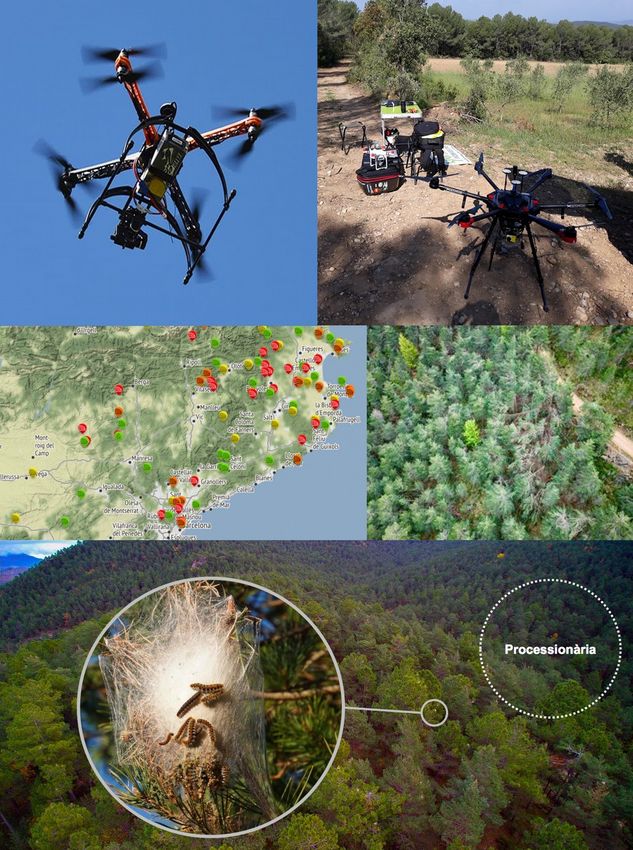
1.3 Real World Scenario
The real-life scenario is set in the near future. We are detecting over time a natural disaster,
with a large area extension of our mountains in Catalonia. It is known that several thousand
hectares of forest areas are affected by different situations from problems with snow in winter
or parasites in trees such as the processionary, forests are very affected, urgently need
emergency supplies forestry, detention and possible supplies of first aid. Time is critical, and a
UAS (dron) with a detention mission is launched from the Research Center at a certain distance
from the affected area.
The UAS (dron) operates automatically, traveling quickly through pre-planned route points to
any affected area, and deliver the information in a safe and accurate way to the Research
Center.
During the mission, find other possible observation beneficiaries in defined areas, and transmit
location coordinates back to the base so that others can observe on subsequent flights.
The mission can be organized. Return to the base through a different route to ensure conflict
with other UAS of surveillance that operate in the area. The mission is repeated in all climatic
© - Sharing passion for flying - 5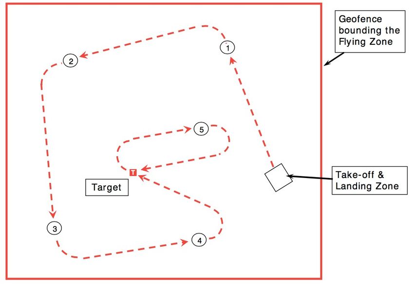
Issue 12 – 2018/19

      conditions until the need to abandon the search yields, maintaining a stable line of information
      in the devastated area and the coordination group sees it as successful completion of the
      mission.

1.4 Structure of this document

       Section 2      presents the overview of the competition, what is involved for participating
                      teams, the schedule of key activities, eligibility and funding;

       Section 3      presents the requirement specification for the UAS, with sufficient information
                      for teams to design and develop the system;

       Section 4      provides the ‘Statement of Work’ for the competition, outlining what is required
                      in each of the stages, including the design review deliverables;

       Section 5      presents the Adjudication and Scoring criteria. This should help the teams in
                      selecting and designing their concept to maximise their score, especially at the
                      Preliminary Design stage;

       Section 6      summarises the Prize categories which will be awarded. These are designed to
                      recognise merit and achievement in a range of areas reflecting the key
                      competition objectives;

       Annex A        provides the representative mission to be flown, and around which the UAS is to
                      be designed;

       Annex B        gives technical details of the GPS tracker to be fitted to the UA, so that teams
                      can make allowance in the design for installation of this item;

       Annex C        provides some general guidance to help the teams develop a practical and
                      competitive UAS;

       Annex D        gives templates and guidance for completion of the three design review
                      deliverables, the PDR, CDR and FRR.

       Annex E        provides guidance to the teams on autopilot selection.

1.5 Publicity
      The Barcelona Smart Drone Challenge (BSDC) publicises the competition during the year to
      encourage participation and to promote the role of the assosiation and STEMcat. Please note
      that participants hereby agree that all content submitted to the BSDC may be used for
      promotional purposes, unless otherwise agreed prior to submission. Images and video taken at
      the flying demonstration event may be used for promotional purposes by the BSDC and its
      partners.

      During the period of the competition, teams are encouraged to publicise the competition and
      their participation – via the media, social media, and for example by talking to local schools or
      other universities, either locally or nationally. A prize is awarded for the most effective use of
      publicity to promote the competition.

                   © - Sharing passion for flying -                                                      6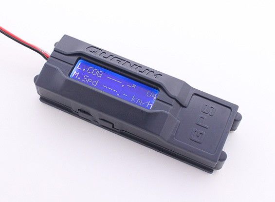
Issue 12 – 2018/19

2 Competition Overview
2.1 Context
     The competition is structured to replicate a real world aircraft system development
     programme, with a phased 9 month design and development process over the course of an
     academic year, and culminating in the build, test and demonstration of the UAS. Deliverables
     have been carefully specified to maintain reasonable technical rigour, yet aiming to keep the
     workload manageable for student teams.

2.2 Generic Mission Task
     The challenge is to design, build and demonstrate a small autonomous UAS to fly a mission
     which is modelled on the real life humanitarian aid scenario described in Section 1.3. The
     competition will vary from year to year, but typically seek to test a number of characteristics,
     such as:

        •     Innovative concepts;

        •     Accuracy of payload delivery to pre-determined points on the ground;

        •     Maximum mass of cargo that can be safely transported in an allocated time;

        •     Quickest time to compete the payload delivery mission;

        •     Navigation accuracy via waypoint co-ordinates provided on the day;

        •     Search object recognition, detecting, recognising and geo-locating objects;

        •     Extent of automatic operations from take-off to landing;

        •     Safety, demonstrating safe design and flight operations throughout;

        •     Minimum environmental impact, notably noise levels and overall efficiency;

        •     Maximum payload / empty weight ratio.

     The representative mission for the 2019 competition is presented at Annex A.

2.3 Development Stages
     The UAS development stages comprise:

        •     Preliminary Design, culminating in the Preliminary Design Review (PDR);

        •     Detail Design, concluding with the Critical Design Review (CDR);

        •     Manufacture of the UAS;

        •     Test;

        •     Flight Readiness, including the Flight Readiness Review (FRR);

        •     Demonstration Event, including the Design Presentation, Scrutineering, Certification
              Flight Test, and the Demonstration (Mission Flight).

     Section 4 provides details of the stages and the ‘Statement of Work’ for the competition.
     Templates for the PDR, CDR and FRR deliverables, together with guidance on what the judges
     are looking for, are provided at Annex E.

     Figure 1 below depicts the competition stages, the key deliverables, the adjudication team

                  © - Sharing passion for flying -                                                  7
Issue 12 – 2018/19

       leading the assessment in each phase, and the main Prize Categories*.

                               Figure 1: UAS Challenge Competition Stages

2.4 Challenge Schedule
       The competition will be launched at the start of the academic year in Octubre. Key activities and
       dates are as follows:

Date          Activity                                                 Deliverable

              2017/18 Competition Launch, coincident with 2018 ;
July 2018                                                              -
              Demonstration event

30 Sep 2018   2019 Rules provided to entrants                          -

15 Feb 2019   Deadline for entries to be received                      Entry form and fee

28 Feb 2019   Preliminary Design Review                                PDR report

30 Mar 2019   Critical Design Review                                   CDR report

17 Jun 2019   Flight Readiness Review submission                       FRR report

              Demonstration Event, including:                          Presentation
                 • Design and FRR Presentation
19, 20 and 21                                                          FRR Scrutiny
                 • Scrutineering
of July 2018                                                           Flight Test
                 • Certification Flight Test
                 • Mission Flight                                      Flight Demonstration(s)

                    © - Sharing passion for flying -                                                  8
Issue 12 – 2018/19

     Adherence to deadlines is a prerequisite for entry into the next stage, and the organizers retain
     the right to eliminate a team in the event that deliverables are not submitted on time.

2.5 Engineering Challenges
     The competition has been designed to give students exposure to a number of disciplines that
     they will need in their engineering careers, and the requirement provides a number of
     engineering challenges. Factors which the judges will be looking for include:

         •   a methodical systems engineering approach to identify the requirements, selection of
             the concept with a design to meet those requirements, and then test to confirm that the
             actual system meets the requirements in practice;

         •   an elegant and efficient design solution, supported by an appropriate depth of analysis
             and modelling;

         •   innovation in the approach to solving the engineering challenges;

         •   due consideration of the safety and airworthiness requirements which shall be
             addressed from the early concept stage right through into the flying demonstration;

         •   appreciation of the practical engineering issues and sound design principles essential
             for a successful, robust and reliable UAS; e.g. adequate strength and stiffness of key
             structural components, alignment of control rods/mountings, servos specified
             appropriately for the control loads, consideration given to maintenance, ease of repair
             in the field;

         •   construction quality, paying attention to good aerospace practice for such details as
             connection of control linkages, use of locknuts, security of wiring and connections,
             resilience of the airframe and undercarriage;

         •   good planning and team-working; organizing the team to divide up roles and
             responsibilities. Good communication and planning will be essential to achieve a
             successful competitive entry, on time and properly tested prior to the Demonstration
             Event;

         •   automatic or autonomous operations; the UAS should ideally be able to operate
             automatically, without pilot intervention from take-off to touchdown;

         •   A strong business proposition for your design, demonstrating good commercial
             understanding of how your design might be developed to generate revenue for an
             operator.

         •   Attention to environmental impact, including minimising noise, developing an efficient
             aircraft design which minimises energy consumption, and attention to minimising use of
             hazardous materials.

     The prize categories (see Figure 1 above and Section 6) aim to recognize merit in overcoming
     these engineering challenges. Guidance notes to help teams are provided at Annex D.

                 © - Sharing passion for flying -                                                   9
Issue 12 – 2018/19

2.6 Eligibility and Team Structure
      The Competition is open to Undergraduates or students from any World University and
      Intermediate cycles of vocational training (FP & CAS). Whilst expected to be predominantly
      a CAT event, entrants from ‘other countries’ universities and middle or higher cycle schools are
      welcomed.

      Teams will be put forward by each University and Middle or Higher Cycle Schools, and will
      constitute members drawn from student cohorts in any year of study.

      A pair of Universities or and Middle or Higher Cycle Schools may form an alliance to enter a
      joint team. Some specialist industry support is to be allowed, where specific skills and
      knowledge are required outside the scope of the undergraduate students.

      The numbers of students in each team will be entirely determined by each University and
      Middle or Higher Cycle Schools. This is so that the educational objectives can be determined to
      meet the needs of each University’s (and Middle or Higher Cycle Schools) degree programmer.
      The competition, whilst having a set of defined performance objectives to achieve, is as much
      about the development and demonstration of team-working skills.

      Please note that attendance at the Demonstration Event is limited to no more than 10
      members per team, plus up to 3 support staff, e.g. pilots or academic staff.

2.7 Sponsorship of Teams
      Universities or and Middle or Higher Cycle Schools are encouraged to approach potential
      commercial sponsors, particularly aerospace companies at any time prior to or during the
      competition, for both financial support and technical advice. Note that where technical advice is
      received from sponsors, the judges will need to be sure that by far the majority of the
      development work has been undertaken by the students themselves. Such sponsorship shall be
      fully acknowledged in the Design Review submissions.

2.8 Cost and Funding
      An entry fee of 900€ (VAT 21% NOT INCLUDED) per team is payable upon submission of an
      entry form. This fee contributes towards the cost of putting on the Demonstration Event. It is
      non-refundable in the event that a team cannot participate in the Demonstration Event.

      We also give the option to the teams that need it to be housed in a campsite within the
      infrastructure of the Barcelona Smart Challenge. With the possibility of staying overnight with
      the rest of the equipment of the electric motorcycle, electric car, electric scooter and drones.
      The price of this, will be given separately depending on the needs of each team.

      Universities and Middle or Higher Cycle Schools shall NOT fund the costs of their UAS design
      and development, and their attendance at the Design Review and Demonstration events.

                 © - Sharing passion for flying -                                                  10
Issue 12 – 2018/19
2.9 Insurance
Teams are required to confirm that adequate insurance is in place, including but not limited to
public liability insurance (minimum XX€) for the team. Declaration that cover is in place must
be made via a liability waiver form which must be submitted with the FRR video and
documents. Teams will not be permitted to participate without this confirmation.
Teams from outside of the European Union or Switzerland are required to present evidence of
medical insurance covering participation in the UAS Challenge fly-off event. This must be
provided with the liability waiver form which must be submitted with the FRR video and
documents. Teams will not be permitted to participate without evidence of cover.
© - Sharing passion for flying - 11Issue 12 – 2018/19
3 Design and Operational Requirements
The UAS shall be designed to perform up to three missions whilst being compliant with the
specification defined in this section. The term ‘shall’ denotes a mandatory requirement. The
term ‘should’ denotes a highly desirable requirement. Where a paragraph is in italics and
preceded by “Note:” this indicates a point of guidance or clarification rather than a design
requirement.
3.1 UAS Requirement Specification
The UAS shall be designed to meet the following constraints and have the following features:
3.1.1 Mission
The ‘Natural Disaster’ mission to be flown is presented at Annex A. Note that details of
Waypoint co-ordinates will be provided at the start of the Demonstration Event.
3.1.2 Airframe Configuration and Mass
Either Fixed Wing or Rotary Wing solutions are permissible, with a Maximum Take- Off Mass
(MTOM) not exceeding 7 kg, including the payload(s).
3.1.3 Propulsion
Electric motors or internal combustion engines are permitted for propulsion.
3.1.4 Electric Systems
For Electric propulsion systems, the LiPo battery voltage shall not exceed 4S cells (14.8V
nominal voltage, 16.8V maximum voltage at full charge). Batteries shall not be ganged together
in series to increase the combined voltage above this limit.
There is no limit on the battery capacity (measured in mAh).
3.1.5 Payload Specification
The payload(s) to be delivered by the UA shall be standard commercially available 250cl of
insecticide liquid, provided to the teams by the organizers at the Demonstration Event.
3.1.6 Payload Carriage and Delivery
The UA shall be designed to carry and release up to one payload, as specified in Section 3.1.4.
The payload(s) shall be individually deployable from the UA by either manual or automatic
command. Only one payload shall be jettisoned at any one instant, i.e. payloads may not be
ganged together and dropped simultaneously.
The payload(s) shall be deployed whilst the aircraft is in flight, from any suitable height above
the ground. The UA is not permitted to land to deploy the payload.
The UA design may incorporate features to provide protection and cushioning of the payload to
keep it intact during the deployment and ground impact, but the payload shall not itself be
modified, for example by permanent reinforcement with duct tape.
The payload can be inserted into a protective module, but without modifying the flour bags in
any way. The flour cannot be decanted into a different container. Protection afforded to the bag
of flour shall be removable without the use of any tools and without damaging the original
packaging. Thus wrapping in bubble wrap is permitted.
To score maximum points, the payload shall remain intact through the deployment and after
© - Sharing passion for flying - 12Issue 12 – 2018/19
impact with the ground.
3.1.7 Autonomy
The UAS shall operate in a fully automatic manner as far as practicable, including automatic
take-off and landing. UAS which are manually operated are permitted, although manual
operation will score considerably fewer points.
Note: Stability augmentation systems do not classify as ‘autonomous’ or ‘automatic’ control, and
shall count as part of manual control.
Note: Automatic take-off implies that the system, after it has been started, can be positioned at
the runway threshold manually, then when the control transferred to platform, it executes the
take-off without human intervention. Auxiliary launch/landing equipment is permitted, so long
as it all operates autonomously. Hand launch is also permitted.
3.1.8 Limits on use of COTS Items
The UAS airframe and control systems shall be designed from scratch, and not based upon
commercially available kits or systems. This is a qualifying rule, meaning that an entrant based
on a commercially available system will not be eligible for consideration.
A guideline maximum value of COTS components used in the UA itself is 1,200€. A Bill of
Materials and costs will be required as part of the design submission. Cost efficient solutions
will score more points.
Teams may use COTS components which already exist at the University and Middle or Higher
Cycle Schools, but for which no receipts are available. An estimate of the price can be obtained
by looking up part numbers or by manufacturer, and a screen shot of the price will suffice.
Teams shall also demonstrate that manufacture of the airframe and integration of the UAS
involves a significant proportion of effort from the students themselves, rather than being
substantially outsourced to a contractor.
Note: Permitted Commercial Off The Shelf (COTS) stock component parts include motors, batteries,
servos, sensors, autopilots and control boards such as the Pixhawk or Ardupilot platforms. Guidance
on potentially suitable autopilots is provided at Annex E. Teams are allowed to use the supplied
software with COTS autopilots, although it may need modifying to meet the specific mission
challenges.
3.1.9 Radio Equipment
All radio equipment and datalinks shall comply with AESA/EU directives, and shall be licensed
for use in the Catalonia (Spain).
Radio equipment, including data links, shall be capable of reliable operating ranges at least of 1
km.
Radio equipment providing control of the UA and the Flight Termination System shall be
‘Spread Spectrum’ compliant on the 2.4 GHz bandwidth, to allow simultaneous testing of several
UAS without interference. Evidence of compliance shall be presented in the CDR submission
and at the Flight Readiness Review.
The radio equipment shall include a buddy box transmitter, which as a minimum shall allow the
Flight Safety Officer to activate the Flight Termination System should this be required.
If an imagery downlink is incorporated, and if it is central to the safety of flight, control or for
Flight Termination decisions, then it shall be suitably reliable and resilient to interference.
© - Sharing passion for flying - 13Issue 12 – 2018/19
3.1.10 Camera / Imaging System
The UA should carry a camera system and target recognition capability to undertake the target
search, location and identification exercise set out in Mission, see Annex A.3.2.
3.1.11 Location Finder
It is recommended that in the event of the UA making an un-commanded departure and
landing outside of the designated Flying Zone, the UA makes an audible/visual warning to
improve ease of UA location.
3.1.12 Tracking System
A GPS Data Logger shall be fitted permitting post-flight evaluation of the 3D trajectory.
Organizers may ask a team member to provide a file with the GPS tracker for each team at the
start of the demonstration event, which operates independently and can be easily integrated
into the UA. A full specification for the new GPS tracker is attached at Annex B. The tracker shall
be easily releasable from the UA, for analysis by the organizers after each flight.
3.1.13 Environmental Impact
In the design process, consideration should be given to environmental impact, including the use
of non-hazardous and recyclable materials; low pollution; low energy usage; low noise.
Teams are encouraged to determine the overall energy consumption of the Mission Flight, as a
measure of the efficiency of the UA. For IC engines, this could be done simply by measuring the
fuel usage, and to facilitate this the fuel tank should be designed to be readily removable from
the UA so that it can be weighed (or contents measured) before and after the flight.
For electric powered UAs, the electrical energy consumed could be measured directly, for
example via a power logger between the ESC and the electric motor. Points will be awarded
both for incorporating into the design the ability to measure the energy consumption, and also
for achieving good efficiency.
© - Sharing passion for flying - 14Issue 12 – 2018/19
3.2 Operational Requirements
3.2.1 Missions
A single mission is defined at Annex A, testing different capabilities of the UAS which would be
important for a humanitarian aid delivery system.
The scoring criteria for the Mission is provided at Section 5.
3.2.2 Take-off and Landing
The UA shall be designed to take off and land from within a 30 m diameter circle. Landing
includes touchdown and roll-out, with the UA required to stop within the box.
The UA should be capable of operating from short grass or hard runway surfaces.
Use of an auxiliary launcher, or hand launch is permitted providing the design and operation is
deemed satisfactory by the Flight Safety Officer and scrutineers.
3.2.3 Design Mission Range and Endurance
For the purpose of sizing the fuel / battery load, the design team should consider Mission in
particular, which is designed to test the endurance of the UAS.
The Mission will not require the UA to operate further than 500 m from the pilot.
For resilience of operation, the radio equipment including data links, shall be capable of reliable
operating ranges of 1 km.
3.2.4 Weather Limitations
The UA should be designed to operate in winds of up to 20 kts gusting to 25 kts, and light rain.
The UA should typically be capable of take-off and landing in crosswind components to the
runway of 5 kts with gusts of 8 kts.
3.2.5 Ground Control Station
If a Ground Control Station is used, it is desirable but not mandated that the following
information should be displayed and be visible to the Operators, Flight Safety Officer and
Judges:
• Current UA position on a moving map;
• Local Airspace, including the Flying Zone;
• Height AGL (QFE);
• Indicated Airspeed (kts);
• Information on UA Health.
In the absence of such live telemetry, the Judges’ and / or Flight Safety Officer’s decision on
boundary breaches is final.
© - Sharing passion for flying - 15Issue 12 – 2018/19
3.3 Safety and Environmental Requirements
3.3.1 Flight Termination System
A Flight Termination System (FTS) shall be incorporated as part of the design and is a
mandatory requirement to achieve a Permit To Fly. The purpose of the FTS is to initiate
automatically all relevant actions which transform the UA into a low energy state should the
data links between the Ground Control Station (GCS) and UA be lost or be subject to
interference / degradation. The FTS shall also be capable of manual selection via the Buddy Box,
should the Flight Safety Officer deem the UA’s behaviour a threat to the maintenance of Air
Safety.
The actions of the FTS must aim to safely land the UA as soon as possible after initiation. The
throttle shall be set to idle / engine off. Other actions could include, but are not limited to:
deployment of a recovery parachute; the movement of all control surfaces to a default position
to achieve a glide; the initiation of a deep stall manoeuvre; movement of the relevant control
surfaces to achieve a gentle turn.
The FTS shall be automatically initiated after 5 seconds lost Uplink. The Uplink is defined as the
data link which provides control inputs to the UA from the GCS (manually or autonomously),
including manual initiation of the FTS.
The FTS should be automatically initiated promptly and no longer than 10 seconds after lost
Downlink. The Downlink is defined as the data link which relays the UA’s telemetry / positional
info and video feed to the GCS.
A ‘Return to Home’ function is not acceptable as an FTS.
3.3.2 Other Design Safety Requirements
The design and construction of the UAS shall employ good design practice, with appropriate use
of materials and components;
The design shall be supported by appropriate analysis to demonstrate satisfactory structural
integrity, stability and control, flight and navigation performance, and reliability of safety critical
systems.
Batteries used in the UA shall contain bright colours to facilitate their location in the event of a
crash;
At least 25% of the upper, lower and each side surface shall be a bright colour to facilitate
visibility in the air and in the event of a crash;
Any fuel / battery combination deemed high risk in the opinion of the judges may be
disqualified.
3.3.3 Operational Safety Requirements
The UA shall remain within Visual Line of Sight (VLOS) and no greater than 500m horizontally
from the Pilot, and remain below 400 ft AGL;
The UA shall not be flown within 50 m of any person, vessel, vehicle or structure not under the
control of the Pilot. During take-off or landing however, the UA shall not be flown within 30 m of
any person, unless that person is under the control of the Pilot1;
The maximum airspeed of the UA in level flight shall not exceed 60 KIAS;
During the entire flight the UA shall remain in controlled flight and within the geofence
© - Sharing passion for flying - 16Issue 12 – 2018/19
boundary of the Flying Zone;
Failure of the Pilot to recover promptly a UA appearing uncontrolled or departing from the
Flying Zone, shall require activation of the FTS, either by the Pilot or at the direction of the FSO.
3.3.4 Pilot Licencing and Insurance
The team pilot shall have a BMFA-A qualification or equivalent (such equivalence shall be
demonstrated to the satisfaction of the BSDC or Educaires). Evidence of qualifications shall be
provided with the FRR submission. The team pilot shall have flown the UAS before (including
during the FRR video).
The pilot shall have appropriate Civil Liability Insurance and Personal Accident Insurance to
cover test flying and the Demonstration Event.
Note: The BMFA offers competitively priced insurance for members.
3.3.5 Environmental Impact
In the design process, consideration should be given to environmental impact, including the use
of non-hazardous and recyclable materials; low pollution; low energy usage; low noise.
Teams are encouraged to determine the overall efficiency of the UA, by measuring the energy
usage (chemical or electrical) during the testing prior to the Demonstration Event.
© - Sharing passion for flying - 17Issue 12 – 2018/19
4 Statement of Work
This section provides more details of the activities and outputs in each stage.
Templates for the deliverable the concept design, PDR, CDR and FRR reports are provided at
Annex D. The schedule for the key milestones and deliverables is provided at Section 2.4.
4.1 Challenge Stages
Figure 1 below depicts the stages of the Challenge, and the key deliverables:
Figure 1: UAS Challenge Stages and Deliverables
Concept: Requirements capture, trade studies, selection of system concept, initial sizing and
performance studies, and generation of the outline design. As a guide this stage is around one
months long and concludes with the Preliminary Design Review (PDR) submission.
Design and desenvolupament: Detailed design for manufacture supported by structural,
aerodynamic, system and performance analysis. This stage should include an assessment of
how the requirements are to be verified through test, and importantly how the safety
requirements are to be met. Some prototyping may also be undertaken. This stage is around 3
months long and concludes with the Critical Design Review (CDR) submission.
Manufature and Test: Construction of the UAS. This may also involve the manufacture of
prototypes during the detail design stage to de-risk the design. Demonstration through
analysis, modelling and physical test that the design will meet the requirements, and is
sufficiently robust and reliable. Physical test should include subsystem test, as well as flight
testing of the complete UAS. This stage concludes with the submission of the Flight Readiness
Review (FRR) submission.
© - Sharing passion for flying - 18Issue 12 – 2018/19
Demonstration: The flying demonstration event is held over two days and comprises a multi-
stage process of qualification and demonstration, including:
• Scrutineering;
• Mission Flights;
• Business Case Presentation.
Further details of the Demonstration Event are provided at Section 4.4.
4.2 Deliverable Items Description
4.2.1 Design Reports
Guidance on the Concept review, PDR, CDR and FRR deliverable items is provided at Annex D.
4.2.2 Design Presentation
Early in the Demonstration Event, each team will give a 12 minute presentation on key aspects
of the design and development to the judging panel. As a guide, the presentation should
include the FRR Video and 5 presentation software slides. There will be up to 8 minutes for
questions. Timings will be strictly enforced.
The assessment panel will be looking to test each team’s communication skills as well as
technical knowledge; demonstrating good teamwork and organization; giving good responses
to questions; demonstrating a clear and concise presentation of the concept selection process,
key design features and supporting analysis, and the development and test programmed.
4.2.3 Environmental Impact Poster
Teams shall produce an A3 size poster summarizing the environmental aspects of the design.
The assessors will be looking for evidence that the team has made efforts to minimize the
environmental impact of the design.
4.2.4 Manufacturing Poster
Teams shall produce an A3 size poster with pictures and summary showing the build, assembly
and test. This shall be submitted to the organizers on arrival at the Demonstration Event, and
will be displayed at the event. The Judges will review the Poster and the Scrutineering Panel will
assess the Manufacturing quality of the physical UA.
4.2.5 Business Case Presentation
During the Demonstration event, teams will be invited to participate in of “Especial invited”
event to pitch their Business Case for the UAS. They should give a well-articulated
understanding of their market, an outline revenue model and sales projections, and summarize
how the UAS capabilities and cost projections align with the target market. Teams will have 5
minutes to present their case, and there will then be 5 minutes of questioning from the Invited.
© - Sharing passion for flying - 19Issue 12 – 2018/19
4.3 Deliverable Items Schedule
The schedule of deliverable items and activities is as follows:
Deliverable Due Date Reference
Concept Review Submission 7 Jan 2019 Annex D.1
Preliminary Design Review Submission 28 February 2019 Annex D.2
Critical Design Review Submission 31 March 2019 Annex D.3
Flight Readiness Review Submission 15 June 2019 Annex D.4
Design Presentation 20-21 July 2019 Section 4.2.2
Environmental Impact Poster 20-21 July 2019 Section 4.2.3
Manufacturing Poster 20-21 July 2019 Section 4.2.4
Business Presentation (*) 20-21 July 2019 Section 4.2.5
* At start of Demonstration Event
4.4 Demonstration Event
4.4.1 Scheduling
4.4.1.1 Timetable
A detailed briefing will be given prior to the Demonstration Event covering the logistics and
timings for the event, rules and good conduct for safe operations, pre-flight briefings etc.
On the first day of July, July 19th, we will welcome the facilities / camping (for those who have
chosen this option) and be able to accompany the time to perform some verification. The
second day, July 2, will be reserved for the verification of the UAS. There will also be an
opportunity to conduct a flying development test for any team that wishes to do so. The rest of
the competition and the entire competition will take place on the 3rd, Sunday, 21st of July.
4.4.1.2 Process
The sequence of events that each team will go through in the preparation and flight operations
is as follows:
▪ Each team will be able to join a queue to be scrutineered as soon as they are ready. It is
important to be ready for scrutineering as soon as possible on the first day.
▪ The scrutineering is conducted in a room adjacent to the hangar. Both the necessary
paperwork and the UA will be scrutinised.
▪ Teams that either fail scrutineering or are not ready will go to the back of the
scrutineering queue.
▪ From Day 2 onwards, those teams that pass scrutineering will proceed outside with the
UA and ground station for a safety controls check.
▪ From there they will then proceed airside for power checks and compass calibration.
▪ Assuming this is satisfactory up to four members of the team together with the UAS will
then be transported to the flightline.
© - Sharing passion for flying - 20Issue 12 – 2018/19
▪ There is then a short brief by FSO, following which the team will be given the go-ahead
and this is when the clock starts ticking. The team then has up to 5 mins to prepare and
take-off, and a further 10 mins to fly the mission.
▪ After the UA has landed, the team has 5 mins to pack up and clear the flight-line. They
will then be transported back to the hangar.
▪ Teams must ensure that all paperwork prepared during the challenge (such as the
completed) is submitted to the organizers during the event, and this will be retained by
the Educaires. Copies may be retained by the team.
4.4.1.3 Readiness
The scheduling of scrutineering and flying is very tight over the 2 day event. Note that the
judges and FSO have ultimate discretion. They will try to ensure that everyone flies, and that no-
one is disadvantaged, but this cannot be guaranteed.
Team readiness for scrutineering and flying is imperative in ensuring an efficient schedule, and
also to maximise your chances of a successful flight. For example paperwork for the scrutineers
needs to be complete and submitted on time.
Note that there may only be time to do one flight per team – so make it count! If all goes well
there may be time to do a second flight, but again this cannot be guaranteed.
Teams shall arrive with a fully serviceable UAS that is in good working condition
4.4.2 Scrutineering
4.4.2.1 Scrutineering schedule
Teams will be allowed to register for scrutineering on a self-assessed readiness basis.
Once they pass scrutineering they may (from Day 2) join the queue for the flight mission. The
schedule is necessarily tight and teams must take responsibility for their readiness to keep a
good tempo of scrutiny and flying.
If a team fails scrutineering they will join the back of the queue and or shall re- register once
ready. They will be given guidance on how to rectify the faults, and the organisers will
endeavour to slot them in for re-scrutineering and the flying schedule at a later point.
Efforts will be made to retain flexibility in the schedule to allow teams who fail scrutineering to
repair, rectify, test and re-apply.
4.4.2.2 Scrutineering process
A panel of expert aircraft engineers will inspect the UAS to ensure that it is safe and airworthy,
that any Corrective Actions made following the CDR submission have been addressed, and that
any late modifications introduced are reviewed and acceptable.
The scrutineering panel will have reviewed the FRR submission (see Annex D.4), which is a key
input to the Scrutineering process as it should contain evidence of satisfactory testing. The
assessment will include:
• Regulatory Compliance – Pass/Fail criteria;
• Control checks – Communications; Function and Sense:
◦ Radio range check, motor off and motor on;
◦ Verify all controls operate in the correct sense;
© - Sharing passion for flying - 21Issue 12 – 2018/19
• Airworthiness Inspection – Structural and Systems Integrity:
◦ Verify that all components are adequately secured, fasteners are tight and are
correctly locked;
◦ Verify propeller structural and attachment integrity;
◦ Check general integrity of the Aid Package and deployment system;
◦ Visual inspection of all electronic wiring to assure adequate wire gauges have been
used, wires and connectors are properly supported;
• Verify correct operation of the fail-safe flight termination systems;
• Manufacturing assessment including:
◦ Design and Build quality, including use of appropriate materials,
◦ systems integration and configuration control;
◦ Attention to detail in assembly and aesthetics;
◦ Sound and safe workshop practices.
A ‘Permit to Fly’ is awarded following satisfactory completion of the Scrutineering, and a green
sticker (max 10 cm x 10 cm), signed by the safety officer, is applied to the UA. This will allow the
team to progress to the Demonstration Flight stage.
4.4.3 Demonstration Flight
4.4.3.1 Preparing for the Mission Flight
Upon successful issue of a Permit to Fly, the Team will have a short time to prepare their
aircraft for the Mission Flight. Note that the flying schedule is likely to be dynamic and updated
during the event to take account of weather and UAS unserviceability.
The Mission is described at Annex A.2, illustrated with example waypoint data. The exact
Mission waypoint and package delivery co-ordinates will be briefed to each team at the start of
the event.
Note that the UA shall be able to do all tasks within the Mission – Aid Package drop, navigation,
reconnaissance, speed, touch and go – without having to land to be reconfigured in any way.
4.4.3.2 Flight Safety and Navigation
During a flight, should the UA stray outside the Geo-fence marking the boundary of the flying
area, the UA navigation system shall automatically detect this and activate the Flight
Termination System (FTS). Failing this, the FSO shall activate the FTS via the command link. This
will result in the termination of the mission.
4.4.3.3 Weather
Weather is a random element – some teams may get good weather over the two days, and
others may have to fly in poorer weather. This is the luck of the draw.
4.4.4 Safety of Operations
The Flight Safety Officer (FSO) shall have absolute discretion to refuse a team permission to fly,
or to order the termination of a flight in progress.
Only teams issued with a ‘Permit to Test’ through the Scrutineering process, and a ‘Permit to Fly’
© - Sharing passion for flying - 22Issue 12 – 2018/19
through the Certification Test Flight, will be eligible to enter the Flying Demonstration stage;
Teams shall be responsible for removal of all batteries from the site that they bring to the
event, including safe disposal of any damaged batteries.
Note that the assessment of safety includes the team members’ attitude to safety of operations,
observing safe working practices in the pit lane doing maintenance, doing what the FSO says at
all times, not transmitting when not approved to.
© - Sharing passion for flying - 23Issue 12 – 2018/19
5 Adjudication and Scoring Criteria
5.1 Overall Scoring Breakdown
The competition will be assessed across four main elements, themselves broken down into sub-
elements:
• Preliminary Design comprising the PDR Submission (50 points);
• Completion of Design comprising the CDR Submission (100 points);
• A3 poster (50 points)
• Flight Demonstration (300 points)
A maximum of 500 points is therefore available. The detail of scoring the Flight Demonstration
is given in the tables below. Note that a satisfactory FRR submission is a prerequisite for entry
into the Flight Demonstration.
5.2 Flight Demonstrations (300)
Task Scoring Max
Score
Navigation
Navigation accuracy Score 50 points for successfully navigating the course, with all WP flown around 50
in the specified direction.
Deduct 10 points per WP missed, up to max penalty of 50 points.
Reconnaissance
Locate Ground Score 15 points for each of four Ground Markers for automatically and correctly 60
Marker reporting the alphanumeric character, and the associated GPS co-ordinates.
Accuracy Accuracy of reported Ground Marker GPS position shall be within 30 m of the
actual position. Outside this scores zero.
Manual reporting Manual reporting of the Ground Marker (such as the judge interpreting the alpha-
numeric from a still or video picture) scores zero.
Aid Package Delivery
Aid Package Mass Score max 40 points for 4 kg of Aid Package mass carried. Score pro-rata for 40
Carried lower mass of Aid Package.
Aid Package Score max 40 points for 4 kg of total Aid Package mass dropped successfully on 40
Delivery Accuracy the target and coming to rest intact and within 30 m of the target centre. Score
pro-rata for lower mass of Aid Package dropped successfully.
Score 0 points for Aid Package mass dropped near the target but coming to rest
either damaged and / or more than 30 m of the target centre.
Precision Touch and Go / Landing
Score 20 points for each controlled approach and landing within the box (total of 40
40 marks for both the touch and go and the final landing). No part of aircraft to
touch the ground outside the box.
Speed Challenge
Score maximum 40 points for a maximum average speed of 60 kts, defined as the 40
course straight line distance around the waypoints divided by the total time
clocked to fly the course. Note the maximum average speed limit of 60 kts must
not be exceeded. Score pro-rata to the fastest average speed (e.g. 50 kts average
© - Sharing passion for flying - 24Issue 12 – 2018/19
speed would score 40 pts x 50/60 = 33 points).
Penalty of 8 points deducted for each WP missed, up to a maximum penalty of 40
points.
Score zero points if maximum average speed limit of 60 kts is exceeded,
measured as an average around the course.
Automatic Operations
Automatic control Score 30 points for fully automatic operation including Take-Off, Navigation, 30
Reconnaissance, Aid Package Drop, Touch and Go, and final Landing.
Score zero points if any parts of the flight control or payload drop are performed
manually.
Operational Readiness
Maximum Mission After 10 minutes from take-off the mission time ends, and no further points can
Time be accrued for any mission tasks underway (e.g. for waypoints, speed, Aid
Package drops, touch and go etc).
Maximum Score: 300
© - Sharing passion for flying - 25Issue 12 – 2018/19
6 Prizes and Awards
There are a number of categories for which prizes will be awarded:
Prize Award Criteria Notes
Grand Champion Highest aggregate score from the PDR, CDR, A3 poster 50 points PDR, 100 points CDR, 50
and the Flight Demonstration points A3 poster, 300 points Mission
Runner Up 2 nd highest aggregate score from the PDR, CDR, A3 50 points PDR, 100 points CDR, 50
poster and the Flight Demonstration points A3 poster, 300 points Mission
3 rd Place 3 rd highest aggregate score from the PDR, CDR, A3 50 points PDR, 100 points CDR, 50
poster and the Flight Demonstration points A3 poster, 300 points Mission
Innovation The most innovative concept taken through to flight Innovative aerodynamic, structures,
demonstration. use of materials, and manufacturing
methods.
Design For the entrant with a well-structured design approach, Evidence of the design tradeoffs
the most elegant and well thought through design, as considered between systems,
described through the Concept Paper, PDR and CDR structures, aerodynamics etc. Elegant
stages that fully meets all the requirements laid down in solutions to meeting the mission
the rules. requirements.
Scrutineer’s The best presented UAS that is fully compliant with the Non-compliant entries will not be
competition rules. permitted to fly.
Safety & For the entrant developing the best combination of a This will take account of the written
Airworthiness well-articulated safety case, with evidence that safety inputs (Concept Paper / PDR/ CDR /
and airworthiness have been considered throughout the FRR) and observations at the
design and development stages, the UAS exhibiting Demonstration event.
practical safety features, and demonstrating safe
operation and team behaviour.
Business For the entrant with the most promising business and Judged by a panel of the event
Proposition marketing case presented to a panel of sponsors during sponsors at the Dragon’s Den event.
the flight demonstration event, reflecting a
wellarticulated understanding of the market and good
alignment of the UAS capabilities and cost projections
with the target market.
Most Promise For the entrant which couldn’t quite make it all work on This could either be a team that failed
the day, but where the team showed most ingenuity, to make it to the flight line or one that
teamwork, resilience in the face of adversity, and a did not reach its full promise during
promising design for next year’s competition. the flight trials.
Highest placed Highest mission scores for a university that has not
new entrant previously taken part.
Media and For the team which engages most effectively with local This is assessed during the Dragon’s
Engagement media, schools, and social media to promote Den event.
participation and engagement with the Challenge.
© - Sharing passion for flying - 26Issue 12 – 2018/19
Annex A - Missions
A.1 General Points
A.1.1 Take-off:
Take-off shall be conducted within the designated take-off and landing box, into wind as far as
practicable. After take-off the system shall maintain steady controlled flight at any suitable
height (Note heights are quoted in feet Above Ground Level (AGL)), typically around 50 m – 120 m (20 ft -
400 ft). Take-off under manual control with transition to automatic flight is permitted, though a
higher score will be given to automatic take-off.
The mission time starts when the team signal they are ready and the Flight Safety Officer gives
clearance for take-off.
A.1.2 Landing:
The UA shall return to and land at the designated take-off and landing zone. The mission is
complete when the UA comes to a halt and the engine is stopped.
A.1.3 Navigation:
Each team will be provided with a map of the airfield, showing the Geo-fence boundary within
which the UA must remain at all times, together with any other no- fly zones. The map will
provide GPS co-ordinates for the Geo-fence vertices, the Waypoints (WPs) and the humanitarian
aid package delivery point.
The mission route will define the WP order. The UA should aim to fly around each WP leaving
the WP correctly to left or right of track as specified, and the accuracy of the navigation will be
evaluated by analysis of the GPS data logger after the flight.
The Flight Termination System shall be automatically initiated upon a breach of the Geo-fence.
The UAS shall navigate around the course automatically, manual control is not permitted.
A.1.4 Operating height:
All operating heights between 50 m – 120 m (20 ft - 400 ft) are valid within the allowable flying
zone. The UA must drop the payload from a minimum of 50 m (20 ft) height above ground, and
cannot land to place the payload (in the case of Rotary Wing UAS). During transit phases
between the landing area to the target area, the UA shall maintain a safe height above ground.
A.1.5 Timing:
With many teams flying, it is essential for the smooth running of the event that teams are
punctual with their timing, and do not over-run the allocated slot time.
To keep up the flying tempo, there will be at least two teams at the flightline at any one time, so
that if one team has to withdraw because of technical problems, another team is immediately
ready to fly.
From arriving at the flightline and being given clearance to take off, a maximum of 5 minutes is
allowed for pre-flight preparation. Additionally an overall maximum time limit of 25 minutes
shall be strictly enforced from a team being given clearance to take-off for a mission flight to
departing the flightline area after the mission. Points will be deducted if the team breaches
these time limits.
If a team cannot get the UAS ready within the 5 minute allowance, the FSO may direct the team
© - Sharing passion for flying - 27Issue 12 – 2018/19
to retire and request another mission slot time, which may be granted at the discretion of the
organisers. Note however that the team may be put to the back of the queue.
A.2 Mission Description
The mission includes multiple tasks conducted under automatic control within a single flight. If
completed successfully the whole mission should last no more than 10 minutes. As a guide, the
distance travelled around the course during the mission may be in the order of 9 - 10 km.
Teams can elect to skip one or more parts of the mission, but they would then score zero for
these elements.
Figure A2 shows an example of the flying area and how WPs may be positioned around the
airfield flying area; Note that this is illustrative only, and details of the actual Geo-fence
boundary to the flying area and WP locations will be provided to the teams at the start of the
demonstration event.
A.2.1 Task 1: Take off
Carrying the heaviest allowable Aid Package within the overall mass limit, the UA shall take-off
and climb out in a controlled manner and head towards the first WP.
A.2.2 Task 2: Navigation
The UA shall navigate around several waypoints located around the airfield. In the example at
Figure A2, the course runs from the Runway to WP1 – 2 – 3 – 4 – 5 – 6 – 7. One or two laps may
be specified.
The UA shall fly around the waypoints in a specified direction, i.e. either leaving the WP to the
right or the left. ‘Cutting the corner’ when flying around a WP will incur penalty points.
A.2.3 Task 3: Reconnaissance
During the navigation task above, the UA shall search for, locate and identify four Ground
Markers, consisting of an alpha-numeric character on contrasting boards, of dimensions given
at Figure A1 in Annex A. These markers will be located around the course at undisclosed
locations on the straight lines linking consecutive waypoints. The accuracy of marker placement
shall be within 30 m of the nominal course. The UA shall report back automatically the alpha-
numeric character within each Ground Marker, and the associated GPS co-ordinates.
If the UA automatically recognises the character through image recognition software, and then
the Pilot shows the judge this from the screen, that is acceptable as automatic reporting.
Manual reporting of the marker is when the judge has to interpret the character from the video
or still images, and this will not score any points.
A.2.4 Task 4: Aid Package Delivery
Having flown around the defined course above, the UA shall proceed from WP7 (in the
example), via WP8 and WP6, to the delivery location and drop an Aid Package (or bundle of Aid
Packages) as close to the delivery location as possible. Points are awarded for successful release
of the Aid Package, it remaining intact on landing, and coming to rest within 30 m of the delivery
location. If the UA has more than one Aid Package bundle, it shall proceed from the target to
WP7 – WP8 – WP6 then to the target and drop a second Aid Package, repeating this until all Aid
Packages have been dropped.
Aid Packages that come to rest greater than 30 m from the target shall score zero for accuracy.
© - Sharing passion for flying - 28You can also read