Bioruptor Pico Sonication System - USER GUIDE - Diagenode
←
→
Page content transcription
If your browser does not render page correctly, please read the page content below

Bioruptor® Pico
Sonication System

                    USER GUIDE
                     Version 6 01_2022
Guarantee
     Limited 5 years global warranty
     Diagenode guarantees the Bioruptor Pico from any manufacturing defects as we rigorously test it to
     meet strict quality standards. Diagenode warrants that all standard components of the instrument
     will be free of defects in materials and workmanship for a period of five (5) years or for maximum
     210 hours of total running time* from the date that the warranty period begins, unless the original
     quotation or accompanying documentation states a different warranty period. The warranty period
     begins on the date of delivery and apply only to the first purchaser of the product. The warranty
     period expires when one of the two above conditions ends (5 years or 210 hours of total running
     time*). If a manufacturing defect arises and a valid claim is received within the warranty period,
     Diagenode, at its discretion, will repair or replace the product in accordance with the warranty

     terms and conditions stated herein. In case of repair or replacement of a product under warranty,
     Diagenode will cover the expenses to return the repaired or replacement product.

     This warranty covers only manufacturing defects and does not cover any damage caused by misuse,
     lack of compliance to recommendations stated in the manual, neglect, accidents, abrasion, or
     exposure to extreme temperatures, chemical solvents, or acids. Improper or incorrectly performed
     maintenance or repairs will void the warranty.

     *The total running time corresponds to total sonication time ON + total sonication time OFF
     that compose the cycles of the shearing process.

     Technical assistance & ordering information
     Diagenode s.a.                     Diagenode LLC.                    Diagenode Co., Ltd.
     BELGIUM | EUROPE                   USA | NORTH AMERICA               JAPAN
     LIEGE SCIENCE PARK                 400 Morris Avenue, Suite          1-1-25, Arakawa
     Rue Bois Saint-Jean, 3             #101                              Toyama 930-0982
     4102 Seraing (Ougrée)              Denville, NJ 07834                Japan
     Belgium                            USA                               Tel: +81 76-482-3110
     Tel: +32 4 364 20 50               Tel: +1 862 209-4680              Fax: +81 76-482-3211
     Fax: +32 4 364 20 51               Fax: +1 862 209-4681

     For the rest of the world, please contact Diagenode s.a.

     https://www.diagenode.com/en/pages/support

Looking for the manual of the previous Bioruptor Pico model? Follow this link :
https://www.diagenode.com/files/products/shearing_technology/bioruptor/Bioruptor_pico_
cooler_manual.pdf
Contents
BIORUPTOR® PICO

Critical steps for maintenance and efficient shearing    6

Introduction                                             7

Technical specifications                                 8

Getting to know you Bioruptor Pico System               11

Equipment installation                                  14

System Operation                                        16

Tube holders & tubes                                    21

BIORUPTOR® COOLER

Safety                                                  25

Design and functions                                    28

Operation                                               38

Maintenance                                             40

Disposal                                                45

Technical data                                          46

                                                             3

BIORUPTOR® PICO

Critical steps for maintenance
         and efficient shearing

         General warnings
              DON’T                                            DO
                 Turn on the instrument without water                 Change water at least once every month
                 Exceed 30 min of total sonication                    Use deionized or distilled water
                 Tilt the sonication unit                             QC your system with our Bioruptor QC Kit

         Sonication bath temperature
            • Optimal temperature for sonication is 4°C. Sample temperature should not exceed 8°C.

            • The Bioruptor Cooler (Cat. No. B02010010, B02010011, B02010012) has to be used to guarantee the
              automatic temperature control of the sonication bath during the entire sonication process.

         Validated tubes for the Bioruptor® Pico
            • DNA shearing: 0.2 ml (Cat.No. C30010020), 0.65 ml (New Cat. No. C30010011; Old Cat. No. WA-005-
              0500) Bioruptor® Microtubes for DNA shearing and Bioruptor 1.5 ml tubes, Cat. No. C30010016.

            • Chromatin shearing: 0.2 ml (Cat.No. C30010020) and 1.5 ml (Cat.No. C30010016) Bioruptor® Microtubes
              and 15 ml (Cat.No. C01020031) Bioruptor® Tubes & sonication beads and 0.65 ml tubes (Cat. No.
              C30010011).

         Fitting tubes in the tube holder
            • Place the tubes in the corresponding tube holder. Never leave empty spaces in the tube holder. Fill the
              empty spaces with tubes containing the same volume of water. Screw the lid on the tube holder without
              over-tightening it.

            • Carefully place the tube holder on the holding plate.

            • During sonication, samples must remain at the bottom of the tube. If needed, briefly centrifuge samples
              during sonication after pausing the run.

6   BIORUPTOR® PICO MANUAL
Which tubes for Bioruptor® pico?

                                                                                                                                 15 ML
                                                                                               1.5 ML
                                                                 0.2 ML          0.65 ML                         15 ML        BIORUPTOR
                                                                                            BIORUPTOR
                                                              BIORUPTOR        BIORUPTOR                      BIORUPTOR       TUBES AND
                                                                                            MICROTUBES
                                                              MICROTUBES       MICROTUBES                       TUBES         SONICATION
                                                                                             WITH CAPS
                                                                                                                                BEADS

                   Catalog number                              C30010020       C30010011     C30010016        C30010017       C01020031

                   Recommended sample volume                  20 µl - 100 µl     100 µl     100 µl - 300 µl   500 µl - 2 ml   500 µl - 2 ml

                   DNA shearing                                     ü              ü              ü
    APPLICATIONS

                   Chromatin shearing                               ü              ü              ü                                ü

                   RNA shearing                                     ü              ü

                   FFPE Extraction                                                                ü

                   Cell lysis                                       ü              ü              ü                ü

                   Tissue disruption for protein extraction                                       ü*               ü*

ü         = validated tubes * Protein extraction beads (C20000021) must be used

                                                                                                                                              7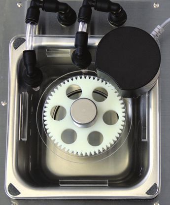
Introduction
         Diagenode’s Bioruptor Pico uses a gentle method of sonication to retain the integrity of
         DNA and/or biological complexes, including chromatin, protein-protein binding, protein-
         DNA complexes and other biochemical and biological assay systems. The Bioruptor Pico
         sonication system uses a sonication bath to generate indirect sonication waves, which
         emanate from an ultrasound element below the water tank. Because the system is gentler
         than other sonicators, the Bioruptor Pico produces better and more consistent results than
         with harsher sonication methods. Up to 16 closed tubes can be sonicated in parallel and the
         continuous rotation of tubes allows even distribution of the energy for efficient sonication.
         The Bioruptor Pico enables automation of sonication, guaranteeing higher reproducibility
         of results.

         The effect of ultrasound on biological sample
         The Bioruptor Pico sonication system uses
         ultrasound to create focused mechanical stress
         to shear chromatin or DNA, remove paraffin from
         FFPE samples, disrupt cells and homogenize tissue,
         disperse chemical component, or reduce the size
         of liposomes. Ultrasound waves pass through the
         sample expanding and contracting the liquid. During
         expansion, negative pressures pull molecules away
         from one another to form a cavity or bubble. This process is called cavitation. The bubble
         continues to absorb energy until it can no longer sustain itself and implodes. This produces
         intense focused shearing forces, that disperse and break biomolecules. The fragmentation
         of chromatin or DNA takes place as a consequence of this mechanical stress or shear. With
         the Bioruptor Pico, the entire volume of water present in the sonication bath is exposed to
         ultrasound, allowing all the samples to be efficiently sonicated in parallel.

         Caution
         As indicated by the “attention” symbol (ISO 7000-0434B) on the Bioruptor cover, this
         instrument is liable to generate noise that may exceed standards for ultrasound in a beam
         around the instrument at 360 °. Exposure to sound waves of 20 to 60 kHz has not been shown
         to be harmful to human health. However, we recommend avoiding unnecessary exposure.
         Also, Diagenode recommends that pregnant women not be exposed to wavelengths of 20
         to 60 kHz for an extended period of time. Finally, Diagenode also recommends limiting
         exposure to ultrasound and using, if necessary, a hearing protection helmet.

8   BIORUPTOR® PICO MANUAL
Bioruptor Pico technical specifications
                                    BIORUPTOR® PICO
 Input Voltage Range                         100 - 240 V ± 10%

 Overvoltage Category                        Category II

 Pollution Degree                            Degree 2

 Input Frequency Range                       50 - 60 Hz

 Maximum Electrical Consumption              4-2A

 Ultrasonic Wave Frequency                   20 - 60 kHz

 Unit Dimensions
     •   The sonicator                       380 (W) x 315 (D) x 275 (H) mm
     •      The cooler                       200 (W) x 390 (D) x 495 (H) mm

 Weight
    •   The sonicator                        9 kg
     •      The cooler                       26.9 kg

 Placement                                   Indoor areas

 Ambient Temperature Range                   15 – 25°C

 Maximum Relative Humidity                   80%

 Altitude                                    Up to 2,000 meters

 Degree of protection                        IP21

                                             • Tube holder for 0.2 ml tubes
                                               Cat. No. B01201144
                                             • Tube holder for 0.65 ml tubes
                                               Cat. No. B01201143
 Shearing Accessories
                                             • Tube holder for 1.5 ml tubes
                                               Cat. No. B01201140
                                             • 15 ml sonication accessories
                                               Cat. No. B01200016

                                             • 0.2 ml Bioruptor Pico Microtubes Cat. No. C30010020
                                             • 0.65 ml Bioruptor Pico Microtubes Cat. No. C30010011
                                             • 1.5 ml Bioruptor Pico Microtubes Cat. No. C30010016
                                             • 15 ml Bioruptor Pico Tubes
 Shearing Consumables                          Cat. No. C30010017
                                             • 15 ml Bioruptor Pico Tubes & sonication beads
                                               Cat. No. C01020031
                                             • Protein extraction beads
                                               Cat. No.C20000021

                                             •   0.2 ml microtubes – 16 samples
                                             •   0.65 ml microtubes – 12 samples
 Throughput
                                             •   1.5 ml microtubes – 6 samples
                                             •   15 ml tubes – 6 samples

                                             •   0.2 ml microtubes – 20-100 µl
                                             •   0.65 ml microtubes – 100 µl
 Sample Volume Range
                                             •   1.5 ml microtubes – 100-300 µl
                                             •   15 ml tubes – 500 µl – 2 ml

 Fragment Length Range Achievable            150 – 1,000 bp

                                                                                                      9
Working Temperature Range                                             2 - 20°C

            Variable Parameters                                                   Time ON, Time OFF, # cycles, level of frequency

            User Interface                                                        Touchscreen with Bioruptor Pico software

                    The instrument must be connected to earth. The electrical outlet serves as a disconnector and must be earthed.

                                              The user must use the Power Cord supplied with the instrument.

                                                   The instrument must stay close to the electrical outlet.

                             If the product is not used according to the manufacturer’s instructions, safety may be compromised.

               MAINTENANCE: The instrument can be visually examined by the user who can also evaluate it with the Bioruptor QC Kit.
                             Only qualified personel at Diagenode can perform a full diagnosis and maintenance.

                                         Use only water to clean the Plexiglass cover. Do not use alcoholic solution.

                                               = Danger of crushing on the gear of the motor plate

               Serial Number label located at the back of your Sonication device
               V = Volt
               A = Ampère
               Hz = Hertz
               Ac = Alternating current
                      = Alternating current
               S/N = Serial Number
               T = fuse slow blow
               H = breaking voltage capacity

10   BIORUPTOR® PICO MANUAL
Getting to know your Bioruptor Pico system
Bioruptor Pico components overview
Sonication bath
Motorized lid
Sonication unit
Power cable (EU) Power cable (US) Tube holder
Bioruptor Cooler (detailed instructions page 21)
11Sonication bath
The sonication bath is a critical component of the instrument. The generators below the
tank produce ultrasonic waves which are then transferred through water. The sonication
bath requires special handling and care as described below.
Handling
The sonication unit must remain upright at all times, especially when moved. Tilting the
sonication unit or handling roughly may damage the ultrasound emitter component,
resulting in a substantial drop in sonication efficiency. If transportation of the apparatus is
required after initial set-up, it is imperative to keep the sonication unit at a right angle to
the ground during the transport at all times.
Water quality
The water bath must be filled with purified water according to specification (see table) to
the fill line. Change water at least every month and clean sonication tank with a soft tissue,
if needed.
COMPATIBILITY
GRADE OF WATER
WITH THE BIORUPTOR
Ultrapure water Type 1 or Type 1+ No
Deionized water Type 2+ or Type 2 Yes
Distilled water Type 3 Yes
Tap water N/A No
Water temperature
The water in the sonication bath must be kept at 4°C. Ultrasonic waves produced by the
Bioruptor Pico generate heat. Drop off in sonication efficiency will occur above 8°C. To
ensure preservation of the samples and to prevent damage to the instrument, it is necessary
to start the sonication process with cold water and to keep it at 4°C during the sonication
process.
Automatic temperature control
The Bioruptor Cooler guarantees the automatic temperature control of the sonication bath
during the entire sonication process. The cooling system produces a regular water flow to
12 BIORUPTOR® PICO MANUALmaintain a constant water level in the tank. The integrated regulating valve ensures that
water will only be replaced during the off cycle to avoid any interference between the water
flow and the sonication process.
Bioruptor® Cooler Sonication unit
Motorized lid
The motorized lid, along with the gear plate accessory, keeps the sample
tubes in constant rotation and ensures optimal position in the sonication
bath during sonication. Avoid the immersion of the motor into the water.
Tube holders
Several sizes of tubes can be used with the Bioruptor Pico.
The minimum and maximum sample volume to be used with each tube is given in the table
below.
TUBE SIZE MINIMUM MAXIMUM
0.2 ml 20 µl 100 µl
0.65 ml 100 µl 100 µl
1.5 ml 100 µl 300 µl
15 ml 500 µl 2 ml
13Equipment installation
The following pages contain information on installing your particular Bioruptor Pico model.
This equipment must only be installed by personnel after reading this section. Consider
all hazards even though no particular hazards have been identified during installation.
Before starting installation work, turn the main switch off and secure the unit against being
re-energized. No special tools are required. One square meter is needed to set up the
Bioruptor Pico.
Devices are designed to be safe under the following conditions:
• Indoor use • Power plug must be grounded
• Altitude up to 2,000 meters • POLLUTION DEGREE 2 (Normally only
non-conductive pollution occurs. However,
• Operating external temperature 15°C to 25°C
occasionally a temporary conductivity caused
(do not install the Bioruptor in a cold room)
by condensation is expected)
• Maximum relative humidity 80%
• N
ever install this equipment in a place where
• T
ransient overvoltage typically present on the environmental conditions and warnings
MAINS supply mentioned above are infringed
• Degree of protection: IP21
Installation overview
Fig. Schematic installation overview of the Bioruptor Pico System in combination with the Bioruptor Cooler.
14 BIORUPTOR® PICO MANUALInstalling the Bioruptor Pico system
Before starting the installation, turn the main switches off and make sure that the unit is
not plugged into an electrical outlet.
1. Open the boxes and unpack all components.
Bioruptor® Pico Bioruptor® Cooler
2. Place the Bioruptor on a bench.
• Important Note: Please make sure that the Bioruptor Pico is always placed on a level surface.
3. Place the Bioruptor Cooler on the bench or below the Bioruptor.
4. Connect the Bioruptor Pico to the Bioruptor Cooler with the cooling long red and blue
isolated tubing by inserting them into the connectors (Optional: Cut the length you
need for the output and input flow. Make sure there is enough slack).
5. Fill the tank of the Bioruptor Cooler with 2 - 3 liter of water and the sonication bath of
the Bioruptor with 700 ml.
6. Plug the valve connection cable into the outlet on the back side of the Bioruptor Cooler
and on the Bioruptor Pico.
7. Plug the power cord into the outlet and switch on the power switch on the back side of
the sonication unit.
8. Plug the power cord into the outlet of the Bioruptor Cooler.
9. Press main switch on the front side of the Bioruptor Cooler.
10. Set the temperature to 4°C.
11. Detailed operating instructions for the Bioruptor Cooler are available on page 21.
15System operation
Touch screen: Allows the user to easily program the sonication of samples.
16 BIORUPTOR® PICO MANUALINTERFACE
Go & Shear: Start a new shearing Settings: Visualize and change the
protocol parameters of your Bioruptor Pico
User Protocols: Record your protocol Sound: Adjust the sound level
Guidelines: Read Diagenode Brightness: Adjust the brightness of the
recommendations for your applications screen
Good Practices: Critical steps for
Bioruptor maintenance and efficient Language: Choose your voice language
shearing
Diagenode dots: Go back to the top
Maintenance: Access for administrators
menu
Information: General information about Technical Support: Diagenode contact
your Bioruptor Pico information for technical questions
Commercial Support: Diagenode contact
Edit: Edit the parameter
information for commercial questions
Question mark: Some notes to guide you
LED LIGHT BAR
The LED light bar allows the tracking of the processing of your samples.
The blue light means the system is waiting for the operator.
The progressive green light indicates the progression of the shearing process.
The green light indicates the end of the shearing process.
The orange light means the protocol is on pause.
The red light indicates an alert message.
17START SHEARING EXPERIMENT
PROTOCOLS
1.
Click on ‘Protocols’ icon of the top menu.
2.
Click on ‘Go & Shear’ icon to start a new
protocol or click on ‘User Protocols’ icon to
find your pre-recorded shearing protocol.
GO AND SHEAR
3.
Select your mode. Find validated parameters
on the Easy Mode or optimize your protocol with
different levels of frequency on the Advanced
Choose validated
protocols
Choose your level
of frequency
Mode.
ENTER PARAMETERS
1.
Enter the sonication time ON, the sonication
GO AND SHEAR (easy mode)
time OFF and the number of cycles. These
30 seconds
are the parameters controlling the shearing
process:
30 seconds
10 cycles - the time ON is the time during which there is
sonication;
10 min 00 seconds - the time OFF is the time during which there
is no sonication but water circulation;
- the cycle is made up of a time ON and a time
OFF.
2.
If Easy Mode was selected, select the tube
type you plan to use. The Bioruptor will
automatically select the correct frequency for
optimal shearing of your samples. If Advanced
Mode* was selected, choose your level of
frequency that is the most convenient for your
application.
18 BIORUPTOR® PICO MANUAL* Easy Mode or Advanced Mode?
The Bioruptor Pico is equipped with several sonication frequencies to adopt to the different consumables compatible
with the Bioruptor (0.2-15ml tubes as listed on page 8). Use the Easy Mode as long validated consumables are used,
as the instrument automatically adjusts the frequency to allow for the most efficient and reproducible sonication.
The frequency does not depend on the actual application (chromatin/DNA/RNA-shearing, cell lysis etc.) but is
crucial for the sonication energy to bypass the tube wall and to create optimal cavitation inside the sample volume.
The Advanced Mode allows to select the sonication frequency manually and is designed for exceptional situations
where non-validated consumables need to be tested. The sonication efficiency is strongly affected by tube material,
thickness and geometry and the 5 different frequencies improve the chances to find suitable settings with any given
consumable type. Sample volumes might require additional optimization with non-validated consumables.
With the validated consumables, frequency changes in the Advanced Mode would NOT improve performance as it
is already optimally pre-set in the Easy Mode.
We strongly recommend the use of validated consumables and the Easy Mode to obtain efficient and reproducible
results with minimal needed sonication time.
If for any reason non-validated consumables need testing, contact customer.support@diagenode.com for further
recommendations.
PREPARE SAMPLES
1.
Fill the sonication tubes with same volume of sample. Use the
recommended tubes and sample volumes for optimal shearing
efficiency. Visit our Guidelines folder for more information.
2.
Vortex and then spin your samples.
3.
Fill all positions of the tube holder with your samples (or with
water of same volume) and place it on the motorized lid.
194.
Close the lid to start the run. The sonication
only starts when the cover is closed. The cover
also prevents noise disturbance.
START PROCESSING & MONITOR PROGRESS
GO AND SHEAR (easy mode) 1.
Click “Go” to start the shearing process. You
will then be asked to check water temperature
30 seconds
and right setting of your samples.
30 seconds
10 cycles
10 min 00 seconds
SHEARING PROCESS
2.
Once the run started, the running screen
appears. The running screen indicates
the elapsed time ON, time OFF and the
11:25
number of cycles. A progress bar and the
Remaining Time:
Remaining:
remaining time will be displayed on the
Sonication ON: 25 seconds screen. The led indicator lights up in green.
Sonication OFF: 30 seconds
Number of cycles: 13 cycles
You can pause or interrupt the shearing
process by pressing the button pause or stop,
respectively. If the cover will be opened during
a run the sonication will automatically pause.
Once the cover is again closed the machine
continues with the sonication process.
3.
You will get a notification on the screen once
the shearing process ends successfully. Click
“OK” to go back to the menu.
20 BIORUPTOR® PICO MANUALTube holders & tubes
The holder is made up of a tube holder and its specific
Tube holder dock.
To guarantee homogeneity of chromatin or DNA shearing,
Dock the tube holders should always be completely filled with
tubes. Never leave empty spaces in the tube holder. Fill
the empty spaces with tubes containing the same volume
of water.
Tube holder for 0.2 ml tubes 15 ml sonication 0.2 ml Bioruptor® 0.65 ml Bioruptor®
(Cat. No. B01201144) accessories Microtubes Microtubes
(Cat. No. B01200016) (Cat. No. C30010020) (Cat. No. C30010011)
Tube holder for 0.65 ml
tubes
(Cat. No. B01201143)
Tube holder for 1.5 ml tubes
(Cat. No. B01201140)
1.5 ml Bioruptor® 15 ml Bioruptor® Tubes 15 ml Bioruptor® Tubes &
Microtubes (Cat. No. C30010017) sonication beads
(Cat. No. C30010016) (Cat. No. C01020031)
21BIORUPTOR® COOLER
Safety

General safety instructions
  • The equipment must only be operated for the intended use under the conditions stated in this operating
    manual. Any other type of operation is considered to be not-intended use and can impair the protection
    provided by the device.

  • The operating manual is part of the device. The information in this operating manual must therefore be
    available in close vicinity to the device. Also store this copy of the operating manual carefully.

Any hazards (electrical shock, fire, contact with movable parts, etc.) caused by the use of
the device must be eliminated as much as possible by the design in accordance with the
appropriate standards. Residual hazards are reduced using any of the following measures:
  • If relevant, there are safety devices for the device. These devices are essential for the safety of the
    device. Their functionality must be ensured with appropriate maintenance activities.

  • If relevant, there are warning symbols on the device. These symbols must always be observed.

  • There are safety instructions in this operating manual. These instructions must always be observed.

  • There are additional specific requirements for the personnel and for the personal protective equipment.

Intended use
The present device is exclusively permitted to be used for tempering and delivering non-
flammable heat transfer liquids to the Bioruptor®.

Non-intended use
The following applications are considered to be not-intended:
  • in potentially explosive areas

  • for tempering foodstuffs

  • with a glass reactor without overpressure protection

  • medical use.

Foreseeable misuse
Misuse of the device must always be prevented.
Among other things, the following uses are considered to be fore- seeable misuse:
  • Operation of the device without heat transfer liquid

  • Incorrect connection of tubes.

                                                                                                              25
Modifications to the device
Any technical modifications to the machine are prohibited. Service works may be carried
out only by qualified personal.
Heat transfer liquid
The device is exclusively designed for nonflammable heat transfer liquids in Class I
according to DIN 12876-1.
Heat transfer liquids are used for the temperature control.
In each case, the heat transfer liquids cover a specific temperature range. This temperature
range must match the temperature range of your application.
The use of heat transfer liquids can cause hazards from high or low temperatures and fire
if certain temperature thresholds are exceeded or undercut or if the container breaks and
there is a reaction with the heat transfer liquid.
The heat transfer liquid safety data sheet specifies all possible hazards and appropriate
safety measures for handling the liquid. The safety data sheet must therefore be consulted
for the intended use of the device.
Materials
All parts coming into contact with the heat transfer liquid are made of high quality materials
suitable for the operating temperature. Stainless steel and temperature-resistant plastics
are used.
Hoses
When selecting suitable hoses for the application, the permissible temperature range and
the maximum permissible pressure must be particularly observed.
Application area
The device is exclusively permitted to be used in the following areas.
• Room temperature (+15 – 25°C)
• Indoor use, no outdoor installation
26 BIORUPTOR® PICO MANUALPersonnel qualification
Operating personnel
Operating personnel are employees that have been instructed by technical staff in the
intended use of the device according to the operating manual.
Personal protective equipment
Protective clothing
• Protective clothing is required for certain activities. This protective clothing must comply with the legal
requirements for personal protective equipment. Protective clothing should have long sleeves. Safety
footwear is additionally required.
Protective gloves
• CE protective gloves are required for certain activities. These protective gloves must comply with the
legal requirements for personal protective equipment of the European Union.
Protective goggles
• Protective goggles are required for certain activities. These protective goggles must comply with the
legal requirements for personal protective equipment of the European Union.
Structure of the safety instructions
Danger
• A safety instruction of the type “Danger” indicates an immediately hazardous situation.
• This results in death or severe, irreversible injuries if the safety instruction is disregarded.
Warning
• A safety instruction of the type “Warning” indicates a potentially hazardous situation.
• This can result in death or severe, irreversible injuries if the safety instruction is disregarded.
Caution
• A safety instruction of the type “Caution” indicates a potentially hazardous situation.
• This can result in minor, reversible injuries if the safety instruction is disregarded.
Notice
• A “notice” warns about possible property or environmental damage.
27Unpacking
Personnel: Operating personnel
1. Unpack the device.
Keep the original packaging of the device for later transport.
2. Inspect the device and the accessories immediately after delivery for completeness and
transport damage.
If there is unexpected damage to the device or accessories, inform the carrier immediately so that a damage
report is produced and a check of the transport damage can be made.
Design and function
Design of the circulation chiller - Front side
1
3 2
1 Top handle
4 5 2 Filler neck with cover
3 Top cover
4 Level indicator
5 Control panel
6 7
6 Overflow tube
7 Drain connection
8 8 Front panel with ventilation openings
9 Four support feet
9
28 BIORUPTOR® PICO MANUALDesign of the circulation chiller - Back side
2 1
1 Supply water connection (blue)
2 Return water connection (red)
3 Mains power socket with fuse
24Vdc socket (to be connected to the
4
4 3 Bioruptor®)
5 5 Back handle
6 Ventilation openings
6
Controls
Mains power switch
The mains power switch can be put in the following positions:
• In position [I], the device is switched on.
• In position [O], the device is switched off.
Control Panel and display buttons
1 Display
1
2 LEDs
2 3 UP arrow button
3
4 ENTER button
4 5 DOWN arrow button
6 6 Mains power switch
5
29Function elements
LEDs for function display
1 Yellow LED: valve
1 3 2 Blue LED: refrigeration
2 3 Red LED: fault
Each device has three LEDs with the following functions:
• The yellow LED lights if the 24 Vdc signal from the Bioruptor is present (open solenoid valve).
• The blue LED indicates whether the refrigeration unit is active.
• The red LED lights in the event of device faults.
30 BIORUPTOR® PICO MANUALHydraulic circuit
Hydraulic circuit
The hydraulic circuit designates the circuit through which the heat transfer liquid flows.
The circuit basically consists of the following components:
• internal storage bath with heat transfer liquid
• pumps for conveying the heat transfer liquid into the external consumer via the pumps connections
Pumps
The devices are equipped with a pressure pump for the supply and a membrane suction
pump for the return.
Level indicator
The fill level of the heat transfer liquid in the circuit can be read
using the level indicator.
The top arrow indicates the maximum liquid level of the machine.
The bottom arrow indicates the minimum liquid level of the machine.
• 1 Maximum level (approx. 3 liters)
• 2 Minimum level (approx. 2 liters)
3.3.5 Refrigeration unit
The refrigeration unit includes the following components
Compressor
A hermetically sealed compressor is used in the refrigeration unit. The compressor
is equipped with overload protection which trips on the compressor temperature and
compressor current consumption.
Condenser
An air-cooled condenser is used in the refrigeration unit. The condensation heat is
discharged to the environment. The fresh air is sucked in through the front of the device
using a fan, heated and discharged on the rear of the device.
Evaporator
In the internal bath, heat is discharged using a pipe coil evaporator.
313.4 Rating plate
The rating plate information is explained in detail in the following table.
SPECIFICATION DESCRIPTION
Type Device type
Order No. Order number of the device
Serial number of the device
Serial No. (Manufacturing year indicated with two digits after the letter “S”)
Voltage Device must only be connected to this voltage and frequency
Refrigerant that is used in the compressor of the device
Refrigerant I (GWP-value indicated in brackets)
Fill quantity of the refrigerant
Fill quantity I (tons of CO2 equivalent in brackets)
maximum permitted operating pressure on the refrigerant high
PS high pressure I pressure side (compressor, condenser)
maximum permitted operating pressure on the refrigerant low
PS low pressure I pressure side (expansion, evaporation)
Current consumption Current consumption of the device during operation
Protection class IP protection class of the device
Fuse Fuse used in the device
Class according to DIN
German standard for electrical laboratory equipment
12876-1
32 BIORUPTOR® PICO MANUALBefore commissioning
EMC classification
Approval of the equipment according to EMC classification
COUNTRIES EMC CLASS
Class B
Europe This classification has been made according to the EMC standard DIN EN
61326-1 (corresponds to VDE 0843-20-1).
Class A
USA This classification has been made according to the FCC (Federal
Communications Commission) regulations, Section 15.
Class A
Canada This classification has been made according to the ICES-003
(Interference Causing Equipment Standards) and NMB-003 regulations.
Instructions for machines, Europe
EMC classification of the equipment:
• Class A: Operation only on mains power supplies without connected residential areas.
• Class B: Operation on mains power supplies with connected residential areas.
In the case of unfavorable mains conditions, disruptive voltage fluctuations can occur.
Instructions for Class A digital device, USA
“This equipment has been tested and found to comply with the limits for Class A digital
device, pursuant to Part 15 of the FCC (Federal Communication Commission) Rules. These
limits are designed to provide reasonable protection against harmful interference when
the equipment is operated in a commercial environment. This equipment generates, uses,
and can radiate radio frequency energy and, if not installed and used in accordance with the
instruction manual, may cause harmful interference to radio communications. Operation
of this equipment in a residential area is likely to cause harmful interference in which case
the user will be required to correct the interference at his own expense.”
33Instructions for Class A digital device, Canada
This Class A digital apparatus complies with Canadian ICES-003” (ICES = Interference
Causing Equipment Standards).
Device Placement
Very specific placement conditions are applicable for the equipment. These placement
conditions are specified in the technical data of the device for the most part.
Additional placement conditions are described below.
• Toxic vapors can be produced depending on the heat transfer liquid used and type of operation. Ensure
sufficient extraction of the vapors.
• Observe the requirements of the device for electromagnetic compatibility (EMC).
• Do not cover the ventilation openings.
WARNING!
Rolling away, falling over of the device
Impact, crushing
• Do not tilt the device.
• Place the device on a level, non-slip surface with sufficient
load bearing capacity.
• Engage the castor brake when setting up the device.
• Do not place any heavy parts on the device.
1. P
lace the device at a suitable location in the room. Place tabletop devices on a suitable
table. Support the device for this by reaching under the device.
2. T
he device requires 20 cm of clearance at the front and rear side in order to allow proper
airflow through the refrigeration unit.
3. T
he device must be installed at RT (10 – 25°C) and can be placed below or at the same
level as the Bioruptor.
34 BIORUPTOR® PICO MANUALCommissioning
Heat transfer liquids
Note the following:
• The heat transfer liquids each cover a recommended temperature range and must be suitable for the
temperature range of your application.
• Never use contaminated or degenerated heat transfer liquid.
Heat transfer liquid water
• See https://www.diagenode.com/files/products/shearing_technology/bioruptor/Bioruptor_pico_
cooler_manual.pdf on page 10
• The alkaline earth ions content (hardness) of the water must be between 0.71 mmol/l and 1.42 mmol/l
(equivalent to 4.0 and 8.0 °dH). Harder water results in lime deposits in the device.
• The pH value of the water must be between 6.0 and 8.5.
• Any chlorine content in the water must be strictly avoided. Do not add any chlorine to the water. Chlorine
is contained, for example, in cleaning agents and disinfectants
• The water must be free of impurities. Water containing iron is unsuitable due to rust formation and
untreated river water is unsuitable due to algae formation.
• The addition of ammonia is not permitted.
Establishing power supply
Personnel: Operating personnel
NOTICE!
Use of unauthorized mains voltage or mains frequency
Device damage
• Compare the rating plate with available mains voltage and
mains frequency.
Also note the following:
• The mains plug of the device provides a mains power disconnection component. The mains plug must
be easily recognizable and easily accessible.
• Only connect the device to an earthed (PE) power socket.
35Switching on device and filling with water
Filling mode
The device has a software program (starting from and including software version 61.15)
that supports the operator for filling the temperature control device. If the fill level is too
low, the Fill mode is started immediately after switching on the device. FILL is shown on
the display and the level indicator is illuminated. The pumps and the refrigerant unit are not
started. When the minimum level has been reached, the pumps are automatically started.
Personnel: Operating personnel
NOTICE! Overheating of the compressor
Device damage
• Never operate water cooled device without cooling water.
DANGER! Use of incorrect heat transfer liquid
Fire
• Select a heat transfer liquid with a temperature range 20 K
above the temperature range of the application
WARNING! Overflow of heat transfer liquid
Electric shock
• Ensure that the device is not overfilled. Note the level indicator
and the thermal volume expansion of the heat transfer liquid
WARNING! Spraying of heat transfer liquid
Electric shock
• Avoid spraying heat transfer liquid. Use a funnel for filling
36 BIORUPTOR® PICO MANUALFill level sufficient
1. Switch on the device using the mains power switch. A signal tone sounds. The software
version is shown on the display. The actual temperature is shown on the display
afterwards.The temperature control device starts operation; the pumps are started.
Depending on the specified set point temperature, the refrigerant unit is started after 2
minutes at the earliest. The blue LED lights if the refrigerant unit is activ
Fill level too low (Low Level)
2. S
witch on the device using the mains power switch. A signal tone sounds. The software
version is shown on the display. FILL is shown on the display afterwards. In the case of
Low Level, the pumps and the refrigerant unit are not started. Fill the device with heat
transfer liquid.
3. Carefully pull up the cover of the filler neck; do not turn.
4. F
ill the heat transfer liquid into the filler neck carefully. Monitor the level indicator. Fill
the device up to the maximum fill level. The pumps start when the minimum level is
reached.
If necessary, use a funnel for the filling.
The level indicator must not be above the maximum fill level.
Fill level drops
5. T
op up the heat transfer liquid carefully as the consumer is now being filled. If the fill
level drops too far, the device automatically goes into the FILL mode and the pump
and refrigerant unit are switched off. Continue with the filling until operation without
problems is possible. Monitor the level indicator for this.
6. Press the cover carefully into the filler neck.
37Operation
Switching on the device
Personnel: Operating personnel
NOTICE! Overheating of the compressor
Device damage
• Never operate water cooled device without cooling water.
1. S
witch on the device using the mains power switch. A signal tone sounds. The software
version is shown on the display. The actual temperature is shown on the dis- play
afterwards. The temperature control device starts operation; the pumps are started.
Depending on the specified set point temperature, the refrigerant unit is started after 2
minutes at the earliest. The blue LED lights if the refrigerant unit is active.
2. D
epending on the water level, heat transfer liquid must be refilled if necessary. Monitor
the level indicator for this.
Default display and set point temperature
1. P
ress the ENTER button to reach set point menu from the default display of the actual
temperature.
If no button has been pressed for longer than 4 seconds, you exit from the set point menu.
2. S
elect a set point temperature (between 2°C and 20°C) using the arrow buttons.
3. T
he changed value or setting is applied immediately by pressing the ENTER button.
Standby mode
The Display shows: “STBY” alternating with the bath temperature.
The device goes into Standby mode if no 24V signal from the Bioruptor is received for a
period of time of more than 2 hours.
In Standby mode the compressor and the pumps are turned off.
If during Standby mode the bath temperature reaches a value higher than 10 K above the
set point, the compressor and the pumps turn on automatically to cool down to set point.
38 BIORUPTOR® PICO MANUALThe compressor and the pumps turn off again when the set point is reached.
If a display button is pushed during Standby mode, the device goes into normal operation
mode.
Sleep mode
The Display shows: “SLEP” alternating with the bath temperature.
The device goes into Sleep mode if no 24V signal from the Bioruptor is received for a period
of time of more than 16 hours.
In Sleep mode the compressor and the pumps are turned off.
If a display button is pushed during Sleep mode, the device goes into normal operation
mode.
39Maintenance
General safety instructions
DANGER! Contact with live or moving parts
Electric shock, impact, cutting, crushing
• The device must be disconnected from the mains power supply
before any maintenance work.
• Repairs must only be carried out by specialists.
CAUTION! Contact with hot / cold device parts, accessories
and heat transfer liquid.
Burns, scalding, frostbite
• Ensure device parts, accessories and heat transfer liquid are
at room temperature before touching them
Also note the following:
Before all maintenance work, you should ensure that decontamination of the device has
been performed if it came into contact with hazardous materials.
Maintenance intervals
The maintenance intervals described in the following table must be complied with. The
following maintenance work is mandatory before every longer unsupervised operation.
INTERVAL MAINTENANCE WORK
daily Inspection of the drain plug by visual inspection from the outside
Inspection of the external hoses for material fatigue
monthly Cleaning of the condenser
Inspection of the heat transfer liquid
40 BIORUPTOR® PICO MANUALCleaning the device
Personnel: Operating personnel
WARNING! Ingress of cleaning agents in the device
Electric shock
• Use a moist cloth for cleaning.
Also note the following:
Only clean the control panel with water and detergent. Do not use acetone or solvents. The
consequence would be permanent damage of the plastic surfaces.
Cleaning air-cooled condenser
Personnel: Operating personnel
1. Switch off the device.
2. R
emove the front cover by holding underneath with both hands and pulling the grating
to the front. Remove the front cover slowly and carefully to prevent damage.
3. Brush off or vacuum the condenser.
4. Remount the front cover carefully.
Checking the heat transfer liquid
Soiled or degenerated heat transfer liquid must be replaced.
Replace fuse
1. Switch off the device.
2. Remove power cord from the main power socket at the back of the device.
3. Remove fuse holder from the main power socket at the back of the device.
4. Replace fuse T5AH 250V (5 ampere time delay fuse with high breaking capacity 250V).
5. Remount fuse holder in the main power socket.
41Cleaning the mesh filter
1. Switch off the device.
2. R
emove the top cover by dismounting the top handle and
unscrewing the two screws at the back of the device.
3. Unscrew mesh filter holder (counter-clockwise).
4. Remove the metallic mesh filter and clean it.
5. Mount the mesh filter back in the holder and screw it back
in the by-pass block (clockwise).
6. Mount top cover and top handle back in the device.
42 BIORUPTOR® PICO MANUALFaults
Alarms, errors and warnings
Any alarms, error signals and warnings triggered on the device are shown on the display as
7-segment text.
Procedure in the event of alarms
Alarms can be cancelled using the ENTER button after rectification of the cause of the fault.
Procedure in the event of warnings
Warnings can be cancelled using the ENTER button after rectification of the cause of the
fault.
Procedure in the event of errors
A two-tone signal is output if any error occurs. The red LED on the device also lights.
In the case of an error, switch off the device at the mains power switch. If the error occurs
again after restarting the device, note the error code and contact the Service partner.
Errors are symbolized with an E and a sequential three-digit number.
43Decommissioning
Draining the device
Personnel: Operating personnel
WARNING! Contact with cold heat transfer liquid
Frostbite
• Bring the heat transfer liquid to room temperature before draining.
Also note the following:
Observe the regulations for disposal of the used heat transfer liquid.
1. Switch off the device.
2. C
onnect the end of an 8 mm exterior diameter pipe to the self-closing drain connector of
the device. Place the other end of the pipe in a container with appropriate capacity under
the level of the device.
3. Let the water flow until the device is completely empty.
44 BIORUPTOR® PICO MANUALDisposal
Disposing of refrigerant
The refrigerant must be disposed of in accordance with EC Directive 303/2008/EC in
combination with 842/2006/EC.
CAUTION! Uncontrolled escape of refrigerant.
Impact, cutting
• Do not dispose of any pressurized refrigerant circuit.
• The decommissioning is only permitted by a specialist.
Global Warming Potential (GWP), comparisons CO2 =1.0
according to IPCC IV - time horizon 100 years - also basis for EU Fluoride Gases Directive 517/2014/EC
Type and fill quantity of the refrigerant can be seen on the rating plate.
Device disposal
The following applies for Europe: The device must be disposed of according to
EU Directive 2012/19/EC.
Disposing of packaging
The packaging must be disposed of in accordance with EU Directive 94/62/EC.
45Technical data
General data
The device sound pressure level is below 70 dB. According to EC Directive 2006/42/EC the sound pressure
level of the devices is therefore not specified further.
SPECIFICATION VALUE UNIT
Placement Indoor areas
Placement height above sea level up to 2,000 m
Humidity Maximum relative humidity 80%
Ambient temperature range 15 - 25 °C
IP protection rating IP 32
Degree of soiling 2
Clearance from surroundings (front and
20 cm
rear sides)
Overvoltage category II and transient overvoltages
Overvoltage
according to category II
Protection class for electrical operating
1
equip- ment DIN EN 61 140 (VDE 0140-1)
Classification according to DIN 12 876-1
I/NFL (non-flammable liquids, only)
(class designation / identification)
Display 7-segment, LED
Display resolution 1 °C
Adjustment resolution 1 °C
Temperature stability +- 2 K
Storage temperature range 5 - 40 °C
Transport temperature range -20 - 60 °C
WORKING TEMPERATURE RANGE DIMENSIONS (W X D X H) WEIGHT
°C mm x mm x mm kg
BC 100 2 - 20 200 x 390 x 495 26,9
46 BIORUPTOR® PICO MANUALCooling capacity
BC 100
Cooling capacity (at 20 °C) W 250
Cooling capacity (at 4 °C) W 120
Refrigerant -- R-134A
The cooling capacity is measured for a specified temperature of the heat transfer liquid. Information is provided
in brackets. The ambient temperature for the measurement is 20 °C; water was used as heat transfer liquid.
Hydraulic circuit
BC 100
Fill capacity l 2-3
Maximum flow rate l/min (water 20 °C) 2
Supply and return
Quick connector (ext. hose diameter in mm) 8
connections
Drain connector Self-closing quick connector (ext. hose diameter in mm) 8
Overflow tube Tube (int. hose diameter in mm) 10
Maximum power consumption
BC 100
kW
230 V; 50 Hz 0.29
115 V; 60 Hz 0.29
100 V; 50/60 Hz 0.29
47www.diagenode.com
You can also read