C-Leg Prosthetic System - Instructions for Use (Qualified Personnel)
←
→
Page content transcription
If your browser does not render page correctly, please read the page content below
C-Leg Prosthetic System
 Instructions for Use (Qualified Personnel)
Charger/AC Adapter
Adapter 757L16-*
4R104=60 4R57 4R41 4R111=N 4R40 4R118
4R104=75 4R57=ST 4R43 4R111
4R89 4R116 4E50-*
with pyramid adapter with threaded connector
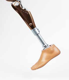
C‑Leg® Knee Joint
Cosmetic Cover/Protector
3C98-2 3C88-2 4X160=1.2
4X150-2 4X73 4X261
Tube adapter Tube adapter 3S26
with torsion unit Cosmetic foam
cover
(not illustrated)
Tube Adapter
3R59
Individual cosmetic
foam cover
2R80 2R81 (not illustrated)
C-Soft (V2.4 and higher)/BionicLink
1A30 1C30 1C40 1D35
4X180=*
Prosthetic Foot
C-Soft
1E56 1E57 1C60 1C61
60X3 BionicLink
60X5 BionicLink PC
1C62 1C63 1C64
Accessories
600 590
580
180 190 570
170
160 200
560
m) 150
125 kg
100 kg
(m
75 kg
4
3
5
en
0
55
6
Rohradapter
8
d
7
Bo
6
14
–
7
se
0
4X78/
ch
5
540
iea
8
Kn
8
kg
max. Systemhöhe 197 mm
max. Systemhöhe 207 mm
max. Systemhöhe 247 mm
max. Systemhöhe 287 mm
max. Systemhöhe 327 mm
min. Systemhöhe 147 mm
min. Systemhöhe 157 mm
min. Systemhöhe 197 mm
min. Systemhöhe 237 mm
min. Systemhöhe 277 mm
125
4
130
nd
kg
sta
7 100
75 kg Stop 3
3
Ab
75 kg Stop
kg
530
75
3
100 kg Stop 100 kg Stop
4 136 kg Stop 125 kg Stop 4
120
4X74 4X77=GB
6
5 5
max. 100 kg
4X83=430-USB
2R82=110 2R82=120 2R82=/2R81=160 2R82=/2R81=200 2R82=/2R81=240
6
520
6
Rohradapter-Auswahlscheibe
5
110
4X79
7 7
3
8 75 kg
8 8
100 kg
125 kg
4 2R82 (Standard) 2R81 (Torsionseinheit) 4
350
510
7 8 Justierbereich Justierbereich
100
136 kg
100 kg
7 C-Leg/C-Leg compact C-Leg/C-Leg compact 5
6
75 kg
3 – Gewindeanschluss – – Justierkern –
System
Systemhöhe Prothesenfuß (mm)
proximale Systemhöhe 23 mm
360
proximale Systemhöhe 5 mm
500
6
distale Systemhöhe 191 mm
distale Systemhöhe 191 mm
totale Systemhöhe 214 mm
totale Systemhöhe 196 mm
Typ Fußgröße 6
5
90
höhe
21 22 23 24 25 26 27 28 29 30 31
1A30 67 68 69 70 71 72 3
5 1C30 81 81 81 81 81 92 101 102 108 109
Pro
kg
7
4 1C40 71 71 81 81 81 87 87 kg 75
kg
kg 1D101 55 58 61 64 67 70 72 74 76
the
100
136 4
370
100
490
kg
1D35 57 60 63 66 68 72 74 75 77
4
kg
kg
80
sen
136
75 8
100
1E56 34 35 35 35 35 36 36 36 36 37
kg
5
Nur in Kombination mit C-Leg compact
8
75
1E57 18 18 18 18 18 18 18 18 18 18
fuß
3
1M101 38 38 44 44 49
6
(m
mit 2C1=*S
7
1M101
7
m)
46 48 53 53 57 59 64 64 64
8
mit 2C1=*N
70
6
380
1C60
480
116 117 118 120 124 125 136
100 kg
75 kg
136 kg
3
mit 2C6=*S
5
4
1C60 126 129 131 140 141 154 156 11
mit 2C6=*N -11
-03
1C61/1C62 163 164 166 167 175 177 177 =D
60 mit 2C6=*S 4X
77
1C61/1C62 k·
173 175 177 181 183 189 191 oc
39
mit 2C6=*N tob
0
Ot
47
1)
©
0
50
400
40 460
410 30 20
450
420 440
430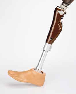
INFORMATION
 These Instructions for Use were updated on 13.03.2012.

Table of Contents
1 Important C-Leg Information – Intended Use...................................................................................................... 4
1.1 Medical Purpose....................................................................................................................................................................4
1.2 Field of Application.................................................................................................................................................................4
1.3 Conditions of Use...................................................................................................................................................................5
1.4 Qualification of the Prosthetist................................................................................................................................................5
1.5 Function.................................................................................................................................................................................5
1.6 Minimum scope of delivery .....................................................................................................................................................5
1.7 Individual minimum system components (not included in the scope of delivery).......................................................................5
1.8 Safety Instructions..................................................................................................................................................................5
General Safety Instructions .........................................................................................................................................................6
Patient Instructions.......................................................................................................................................................................7

2 Alignment and Adjustment................................................................................................................................. 10
2.1 Connecting the Tube Adapter...............................................................................................................................................10
2.2 Bench Alignment Using an Alignment Tool such as L.A.S.A.R. / PRO.S.A. Assembly............................................................11
2.2.1 Checking the Socket after Bench Alignment......................................................................................................................12
2.3 Torque Values of the Screw Connections..............................................................................................................................13
2.4 Charging the C-Leg Prosthesis System................................................................................................................................13
2.6 BionicLink/Optional: Serial Data Cable................................................................................................................................15
2.7 C-Soft 15
2.8 Optional: Parameter Settings with Foam Cover and C-Soft..................................................................................................15
2.9 C-Leg Modes.......................................................................................................................................................................16
2.9.1 1st Mode, 2nd Mode and 3rd Mode.................................................................................................................................16
2.9.2 Standing Mode Function in the 1st Mode...........................................................................................................................19
2.9.3 Optimization of the Damping Behaviour in the 1st Mode....................................................................................................21
2.10 Pairing of the Remote Control and Battery Change............................................................................................................22
2.10.1 Pairing.............................................................................................................................................................................22
2.10.2 Battery Change...............................................................................................................................................................22
2.11 Finishing the Prosthesis......................................................................................................................................................23
2.12 Important User Instructions.................................................................................................................................................23
Safety mode...............................................................................................................................................................................23
Battery capacity.........................................................................................................................................................................24
Empty battery mode ...................................................................................................................................................................24
Safety signal for incorrect connection to the tube adapter..........................................................................................................24
Ventilation 24

3 Additional Information........................................................................................................................................ 25
3.1 Service Intervals...................................................................................................................................................................25
3.2 Damage Event......................................................................................................................................................................25
3.3 Technical Information............................................................................................................................................................25
3.3.1 Symbols on the Joint..........................................................................................................................................................25
3.3.2 Symbols on the Remote Control........................................................................................................................................25
3.4 Transportation......................................................................................................................................................................26
3.5 Guaranty..............................................................................................................................................................................26
3.6 Liability.................................................................................................................................................................................26
3.7 CE Conformity......................................................................................................................................................................26

Explanation of Symbols used in these Instructions for Use
   DANGER    Warnings regarding directly impending risks of severe accident or injury.
   WARNING   Warnings regarding possible risks of severe accident or injury.
   CAUTION   Warnings regarding possible risks of accident or injury.
 NOTICE   Warnings regarding possible technical damage.

Recommended accessories for prosthetists
710D4                           Torque Wrench
710Y2=5                         Hex Bit
743L100                         L.A.S.A.R Posture             (647H189 Instructions for Use)
743L200/743L300                 L.A.S.A.R Assembly            (647H193 Instructions for Use)
60X3                            BionicLink                    (647G192 Instructions for Use)
4X180=* (V2.4 and higher)       C-Soft                        (647G268 Instructions for Use)

1 Important C-Leg Information – Intended Use
 INFORMATION
 Before using the C-Leg, please read these Instructions for Use thoroughly! Please pay special attention to the
 safety instructions!
 The patient must be taught how to handle, care for and operate his/her prosthesis properly.
 Please see the following Sections: 1.3 Conditions of Use; 1.8 Safety Instructions; 2.4 Charging the C-Leg Pros-
 thesis System; 2.9 C-Leg Modes, 2.12 Important User Instructions; 3.1 Service Intervals; 3.3 Technical Informa-
 tion; 3.6 Liability.

1.1 Medical Purpose
The 3C98-2 and 3C88-2 C-Leg knee joints are to be used exclusively for the exoprosthetic fitting of the lower
extremity.

1.2 Field of Application
The C-Leg was designed for a broad field of application and can be used by transfemoral amputees as well as by
active hip disarticulation amputees. For knee disarticulation amputees, a version for long residual limbs is available
(3C88-2).

Field of application according to the Ottobock MOBIS® Mobility System:
Recommended for Mobility Grades 3 and 4 (unrestricted outdoor walkers and unrestricted outdoor
walkers with especially rigorous demands).
The patient must meet the following requirements:
• The patient must meet the physical and mental requirements with regard to the perception of
   acoustic signals and/or mechanical vibrations.
•The skin on the residual limb must be fully healed.
Approved for a patient weight of up to 136 kg/300 lbs.
Exception: T he 2R82=110 Tube Adapter is approved for a patient weight of up to
            100 kg/220 lbs.
            The 2R81=* Tube Adapter is approved for a patient weight of up to 125 kg/275 lbs.

4 Ottobock                                                                                     C-Leg Prosthetic System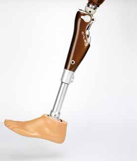
1.3 Conditions of Use

 INFORMATION
 Advise your patients of the information in this section.

The C-Leg was developed for everyday activities and not for extreme sports such as free climbing, parachuting or
paragliding. For the necessary environmental conditions, please see Section 3.3 “Technical Information”.
The C-Leg prosthesis system is designed exclusively for use on one patient. Use of the product by other persons
is not approved by the manufacturer.

1.4 Qualification of the Prosthetist
The fitting of a patient with a C-Leg may only be carried out by prosthetists who have been authorized with the cor-
responding Ottobock training.

1.5 Function
The 3C98-2/3C88-2 C-Leg is a hydraulically damped, monocentric knee joint with fully microprocessor-controlled
stance phase and swing phase. Strain gauges in the tube adapter measure the anterior and posterior bending
moment; a knee angle sensor measures the flexion angle and angular velocity of the knee joint. These measured
variables are transmitted to the microprocessor, which then calculates the necessary movement resistance. Ser-
vomotors correspondingly open and close hydraulic valves to provide the required flexion and extension damping.
This allows the C-Leg to adapt in real time to the individual requirements and the activities of the prosthesis wearer.
Additional modes permit activities such as cycling, cross-country skiing or inline skating.

1.6 Minimum scope of delivery
1 pc. 3C98-2/3C88-2 C-Leg Knee Joint
1 pc. 4X150-2 C-Leg Remote Control

1.7 Individual minimum system components (not included in the scope of delivery)
1 pc. 2R82=* C-Leg Tube Adapter
1 pc. 2R81=* C-Leg Tube Adapter with Torsion Unit

1.8 Safety Instructions

 INFORMATION
 Advise your patients of the information in this section.

     CAUTION
 Non-observance of safety instructions. Failure to follow the below-mentioned safety instructions can lead to
 a faulty control or malfunction of the C-Leg and result in risk of injuries for the patient as well as damage to the
 C-Leg.

C-Leg Prosthetic System                                                                                   Ottobock      5
General Safety Instructions
    CAUTION
Alignment and adjustment error. During alignment and adjustment of the prosthesis, errors can occur result-
ing in malfunction of the joint up to loss of function due to structural failure. This can cause the patient to fall.
• Participation in an Ottobock product training course for the C-Leg is obligatory before the first fitting.
   Additional product training courses may become necessary to qualify for fitting product updates.
• The tubes must not be shortened as that may damage the integrated strain gauges.
• During the data transfer (PC to C-Leg), the prosthesis wearer must remain standing or sitting still and the
   BionicLink or the communication cable must not be removed.
• If the prosthesis wearer uses crutches or walking canes during adjustment, readjustment is required as soon
   as he stops using these walking aids.

    CAUTION
Use of inappropriate prosthetic components. If inappropriate prosthetic components are installed in the
prosthesis, malfunction of the joints can occur up to loss of function due to structural failure. This can cause the
patient to fall.
Combine the C-Leg only with adapters and feet approved by Ottobock (see component overview on the folded
front page).

    CAUTION
Manipulations on system components. Any changes or modifications you make to system components on
your own initiative can lead to malfunction of the joint up to loss of function due to structural failure. This can
cause the patient to fall.
• Any changes or modifications to the device may limit its use.
• The opening and repairing of the joint may only be performed by authorized Ottobock technicians, and the
   handling of the battery may only be carried out by Ottobock Service Centres (exchanges are not permissible).

    CAUTION
Incorrect battery charging. Charging the battery with battery chargers that have not been approved by Ottob-
ock can lead to defects and result in malfunction of the joint. This can cause the patient to fall.
Advise the patient about the charging procedure and refer to the Patient Information. Advise the patient of the fol-
lowing patient instructions.

    CAUTION
Improper use of the joint. Any kind of overloading or excessive strain as well as improper use can lead to de-
fects and result in malfunction of the joint up to loss of function due to structural failure. This can cause the patient
to fall.
Advise the patient of the proper use of the C-Leg as well as of the following patient instructions.

    CAUTION
Improper use of the remote control. The remote control can get damaged by improper use. This can lead to
malfunction of the remote control and result in unexpected actions of the joint. This can cause the patient to fall.
Advise the patient about the proper use of the remote control and refer to the Patient Information. Advise the
patient of the following patient instructions.

    CAUTION
Switching between modes with the remote control. When switching between modes with the remote con-
trol, the damping behaviour of the joint changes. In certain situations, this can cause the patient to fall.
Advise the patients about the switching into the 2nd mode and refer to the Patient Information. Advise the patient
of the following patient instructions.

6 Ottobock                                                                                     C-Leg Prosthetic System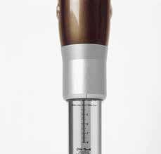
CAUTION
Transport damage. Mechanical impact or stress during transportation of the joint such as shocks and vibra-
tions can lead to
• defects and result in malfunction of the joint;
• defects on the battery and hydraulic damper resulting in leakage of liquid; or
• loss of function due to structural failure.
This can cause the patient to fall as well as result in skin irritation.
Always use the transport packaging for transport.

    CAUTION
Results of product deterioration. Wear and tear on system components can lead to malfunction of the joint.
This can cause the patient to fall.
In the interest of the prosthesis wearer (maintenance of operational safety and guaranty), the specified service
intervals must be complied with.

Patient Instructions

    CAUTION
Magnetic interferences. The joint can malfunction when near high-tension power lines, transmitters, transform-
ers, CT scanners, or other sources of strong electromagnetic radiation (such as security systems for goods in
department stores). This can cause the patient to fall.
Avoid proximity to strong magnetic and electric interference sources (e.g. transformer stations, high-powered
radio or television transmitters).

    CAUTION
Thermal overloading. Extended exposure to high temperatures can lead to defects and result in malfunction of
the joint up to loss of function due to structural failure. This can cause the patient to fall.
Avoid areas with extreme temperatures (see Section 3.3 “Technical Information”).

    CAUTION
Mechanical overloading. Exterior mechanical impact or stress such as shocks and vibrations can lead to
• short circuits in the electronics and battery and result in malfunction of the joint;
• defects on the battery and hydraulic damper resulting in leakage of liquid; or
• loss of function due to structural failure.
This can cause the patient to fall as well as result in skin irritation.
Do not expose system components to mechanical vibrations or shocks.

    CAUTION
Penetration of dirt and humidity. Penetration of dirt and humidity into the system components can lead to
• short circuits in the electronics and battery and result in malfunction of the joint;
• defects on the hydraulic damper resulting in leakage of liquid; or
• loss of function due to structural failure.
This can cause the patient to fall as well as result in skin irritation.
• Do not let foreign particles or liquids enter the system components. Should the joint come into contact with
   liquid, remove the cosmetic cover and let the components dry. The joint must then be sent to an authorized
   Ottobock Service for inspection. Your prosthetist is the contact person.
• Always use the plug protectors / plug covers.
• If the C-Leg comes into contact with salt water, immediately clean it with a cloth moistened with freshwater
   and let it dry. The joint must then be sent to an authorized Ottobock Service for inspection. Your prosthetist is
   the contact person.

C-Leg Prosthetic System                                                                                  Ottobock      7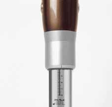
CAUTION
Improper use of the joint. Any kind of overloading or excessive strain as well as improper use can lead to
• defects and result in malfunction of the joint;
• loss of function due to structural failure; or
• defects on the battery and hydraulic damper resulting in leakage of liquid.
This can cause the patient to fall as well as result in skin irritation.
• The C-Leg was designed for everyday activities and must not be used for unusual activities such as extreme
   sports (i.e. free climbing, paragliding, etc.).
• Careful handling of the prosthesis and its components not only increases their service life but, above all,
   ensures your personal safety. Should the prosthesis be subjected to unusual stresses (such as a fall), immedi-
   ately contact your prosthetist and have the prosthesis inspected for any damage. If necessary, the responsible
   prosthetist will pass the prosthesis on to the Ottobock Service Centre.

    CAUTION
Overheating of the hydraulic unit. Extended, continuous use (e.g. lengthy downhill walks) can lead to
• overheating of the hydraulic unit and result in malfunction of the joint; or
• defects on the hydraulic damper resulting in leakage of liquid.
This can cause the patient to fall as well as result in skin irritation. Touching overheated components can cause
burns.
• Pay attention to the vibration signals that will occur in such cases to alert you that there is a risk of overheat-
   ing. As soon as these vibrations begin, all activities must be stopped and the hydraulic unit be allowed to cool
   down. You may resume your activities once the vibration signals stop.
• If activities are continued despite the vibration signals, the hydraulic element may overheat and, in extreme
   cases, lead to a damage to the C-Leg. The joint should then be sent to an authorized Ottobock Service for
   inspection.

    CAUTION
Risk of falling when walking backwards. When putting down the toe first when walking backwards, the
C‑Leg® can switch from the high stance phase resistance to swing phase resistance. When the patient actively
flexes the hip joint at this point in time, this can cause the patient to fall. When walking backwards, secure the
joint actively with the residual limb muscles.

    CAUTION
Risk of falling when going downstairs. When walking downstairs, the banister or handrail should always be
used and the prosthetic foot should be placed on the step so that the heel (max. centre of the foot) is close to the
edge of the step to facilitate rollover.
• Stop walking downstairs immediately whenever the sound warning beeps. Make careful tests to verify if the
   stance phase stabilization is active (see Section 2.12 “Important User Instructions“).
• Pay attention to the vibration and sound warnings (beeps) of the C-Leg.
• Special caution is required when walking downstairs while carrying children.

    CAUTION
Non-active safety mode. If the safety mode can no longer be activated, there is the risk that the patient will fall.
If the C-Leg does not switch to the safety mode (e.g. due to short-circuit due to water penetration), the am-
putee must actively stabilize the C-Leg at heel strike with his/her residual limb muscles until a prosthetist can be
reached or a prosthesis replacement be accomplished.

8 Ottobock                                                                                   C-Leg Prosthetic System
CAUTION
Self-discharge of the battery. When the joint is not in use for an extended period of time, self-discharge of the
battery will result. This can lead to insufficient power supply to the electronics of the joint and result in undefined
conditions. This can cause the patient to fall.
• We therefore recommend recharging prior to every use.
• Prior to using the C-Leg in the 2nd/3rd mode (e.g. bike riding), check the battery status. To do so, attach the
charger to the C-Leg. The yellow LED should flash (battery is charged more than a half) or should not be lit
(battery is fully charged). Using the C-Leg in the 2nd/3rd mode with insufficient battery capacity may cause
the C-Leg to switch into the safety mode (see Section “2.12 Important User Instructions”).
CAUTION
Improper switching between modes. An incorrect switch from the 2nd/3rd mode into the 1st mode creates
the risk of falling (see Section 2.9 “C-Leg Modes”)!
CAUTION
Switching between modes with the remote control. The patient can use the remote control to initiate dif-
ferent actions. As a result the damping behaviour of the joint will change. In certain situations, this can cause the
patient to fall.
In the case that you have mistakenly selected an unwanted action with the remote control (vibration or sound
signal), unweight the C-Leg and select a new command.
WARNING
Risk of accident when driving a motor vehicle. The ability of leg prosthesis users to drive a motor vehicle
is determined on a case-by-case basis. Criteria include the type of fitting (amputation level, unilateral or bilateral,
residual limb conditions, design of the prosthesis) and the amputee’s individual abilities. All persons are required
to observe their country’s national and state driving laws when operating motor vehicles. For insurance purposes,
drivers should have their driving ability examined and approved by an authorized test centre. Ottobock recom-
mends that the motor vehicle be professionally retrofitted to the user’s individual needs (e.g. automatic shift). Risk-
free driving must be ensured even when the leg prosthesis is not functioning.
Before operating a motor vehicle, make sure to turn off the standing mode feature using the remote control unit.
CAUTION
Malfunction of the joint. Malfunctions of the joint can cause the prosthesis wearer to fall.
Pay attention to the vibration and sound warnings (beeps) of the C-Leg.
INFORMATION
When using exoprosthetic knee joints, servomotoric, hydraulic, pneumatic or brake load dependent control func-
tions can cause movement noise. This kind of noise is normal and unavoidable. Usually, it does not cause any
problems.
If the movement noise noticeably increases in the knee joint‘s life cycle, the joint should be inspected immediately
by a prosthetist.
CAUTION
Risk of pinching where the joint bends. Ensure that fingers and other body parts are not in this area when
bending the joint.
C-Leg Prosthetic System Ottobock 92 Alignment and Adjustment
2.1 Connecting the Tube Adapter
1 2 3 4
1 Mount the foot to the tube adapter (lightly tighten the screws).
2 Plug the tube adapter plug into the knee joint (only one polarity possible).
3 Push the protruding cable into the tube and push the tube adapter into the C-Leg. In doing so, take care to
achieve the minimum insertion depth (see following table).
max. 75 kg 75 kg - 100 kg 100 kg - 136 kg
50 mm 45 mm 40 mm
max. adjust- max. adjust- max. adjust-
ment range ment range ment range
CAUTION Error during alignment of the prosthesis. Errors during the alignment of the prosthesis can lead
to malfunction of the joint up to loss of function due to structural failure. This can cause the patient to fall. With the
3C98-2 and 3C88-2 models, the scaling must be positioned in front of the tube (With the former models 3C98 and
3C88, the scaling had to be on the back of the tube). The 2R82=110 Tube Adapter is approved for a maximum
weight of 100 kg/220 lbs, the 2R81=* Tube Adapter is approved for a maximum weight of 125 kg/275 lbs.
4 Turn the foot slightly outward (adjustment range +/-30° to suit the needs of the patient) and pre-fasten the
screws lightly at the clamp.
10 Ottobock C-Leg Prosthetic System2.2 Bench Alignment Using an Alignment Tool such as L.A.S.A.R. / PRO.S.A. Assembly
INFORMATION
To align the prosthesis please proceed in two steps:
First make the bench alignment using an alignment tool such as 743L200 L.A.S.A.R. Assembly / 743A200
PRO.S.A. Assembly.
In a second step, the static alignment is optimized with the 743L100 L.A.S.A.R. Posture (see Section 2.5 “Static
Alignment Optimization”).
A MF
M
30 mm
5 mm
+5 mm A
3°- 5°
1 A
M
MF
+ 5 mm
32 2 4
A correct bench alignment (e.g. using the 743L200 L.A.S.A.R. Assembly / 743A200 PRO.S.A. Assembly.) ensures
that the user can benefit from all the advantages of the C-Leg. The optimal residual limb position must be anticipat-
ed when positioning the socket connector. Plumb lines in the frontal and sagittal planes (drawn from the hip joint’s
centre of rotation and marked during plaster cast taking and trial fitting of the test socket) will facilitate correct
positioning of the lamination anchor or socket adapter.
• Position the middle of the foot (MF) approx. 30 mm anterior to the alignment reference line (A). This applies to all
feet that are recommended for use with the C-Leg, independently of the specifications in the instruction manuals
of those feet!
Add 5 mm to the required heel height. Set correct outward rotation of the foot (Fig. 1).
• Clamp the knee joint with the mounted tube adapter into the alignment tool. Place the alignment reference
point (=knee axis) approx. 0-5 mm anterior to the alignment reference line. Consider the knee-floor distance
and outward rotation of the knee (approx. 5° are provided for by the adapter insert in the L.A.S.A.R. Assem-
bly / PRO.S.A. Assembly.). Recommended positioning of the alignment reference point: 20 mm above the medial
tibial plateau (Fig. 2).
• Connect the foot to the modular knee joint using a tube adapter. To do so, tilt the joint in the correct position and
set the required tube length (Fig. 2).
• Mark the centre of the socket proximally (M) and distally on the lateral side. Draw a line through both marks from
the socket brim to the distal end of the socket (Fig. 3).
Now position the socket such that the alignment reference line (A) passes through the proximal centre mark (M).
Set the socket flexion to somewhere between 3° and 5°; however, the individual situation (e.g. hip joint contrac-
C-Leg Prosthetic System Ottobock 11tures) must be taken into account and, if necessary, more flexion should be provided. Also pay attention to the
ischial tuberosity to ground distance (Fig. 4).
CAUTION Error during alignment of the prosthesis. Errors during the alignment of the prosthesis can lead
to malfunction and insufficient fitting results of the joint up to loss of function due to structural failure. This can
cause the patient to fall.
If the residual limb flexion is not taken into account, the joint will be positioned too far to the front.
• Connect the socket and modular knee joint using a corresponding adapter (e.g. 4R111, 4R41 Socket Adapter,
etc.). For alignment correction, use the 4R112 Sliding Adapter (only for temporary use!). When using socket
adapters with a 4-hole connection (e.g. 5R1=*, 5R6=*), the 4R118 Sliding Adapter can be used for a perma-
nent, additional posterior placement of 10 – 25 mm.
CAUTION Error during alignment of the prosthesis. If incorrectly positioned, the support for the lamination
anchor is not provided. This puts too much strain on the screwed connection adapter and may cause damage
and subsequently cause the patient to fall. The rotation adjustment must not be used for length adjustment.
Screw in the thread adapter as far as possible and clamp with the cap screw. In case of the 4R43 Lamination
Anchor with threaded connector, position the clamp laterally or medially. In case of the 4R111=N Lamina-
tion Anchor with threaded connector, the anchor arms must be positioned in the anterior/posterior and me-
dial/lateral directions. Here, the clamp must be positioned to show in the anterior/medial or anterior/lateral
direction.
• Confirm the bench alignment and all measurements.
2.2.1 Checking the Socket after Bench Alignment
CAUTION Error during alignment of the prosthesis.
Errors during the alignment of the prosthesis can dam-
age the hydraulic unit of the joint. A defective hydraulic
unit can lead to malfunction of the joint up to loss of
function due to structural failure. This can cause the
patient to fall.
3 mm The hydraulic unit may become damaged by contact
1/8"
with the socket! At maximum flexion and insofar as
contact with the frame of the C-Leg cannot be avoided
(in case of voluminous residual limbs), the socket must
5 lie flat on the frame. Soft cushioning at the socket will
assist in maintaining the socket flat. At maximum flexion,
it is essential that the minimum distance of 3 mm (1⁄8") is
maintained between the hydraulic unit and the socket.
CAUTION Error during alignment of the prosthesis.
5 mm
Errors during the alignment of the prosthesis can dam-
1/5" age the electronics of the joint. Defective electronics
can lead to malfunction of the joint. This can cause the
patient to fall.
The electronic unit may become damaged by contact
with the socket! At maximum extension (reached under
full capacity load!) the minimum distance of 5 mm (1/5”)
must be maintained between the electronic unit and the
socket at the beginning of the dampening phase.
6 For fittings with the 4X160=* C-Leg Protector, the
minimum distance between the electronic unit and the
socket must be at least 10 mm (3⁄8").
CAUTION
Error during alignment of the prosthesis. If the socket drain or air expulsion hole is incorrectly positioned,
the draining sweat may drop into the electric connector and lead to short-circuits in the electronics and malfunc-
tion of the knee joint which may subsequently cause the patient to fall.
Make sure the socket drain or air expulsion hole is not positioned frontally above the electric connector. Position
the hole on the side or back of the socket.
12 Ottobock C-Leg Prosthetic System2.3 Torque Values of the Screw Connections
INFORMATION
The torque values for additional as well as optional system components (in item 3 below) are indicated in the
Instructions for Use of those products.
15 Nm 10 Nm
15 Nm 7 Nm
1 2 3 4
Using the 710D4 Torque Wrench with the 710Y2=5 Hex Bit, turn the screws alternatively to the prescribed torque
so that the torque is gradually increased:
1 Tube adapter: 15 Nm
2 Clamp: 7 Nm
Fitting for short residual limb
3 Rotation adapter or sliding adapter: 15 Nm
Fitting for long residual limb
4 Lamination anchor with threaded connector: 10 Nm
2.4 Charging the C-Leg Prosthesis System
INFORMATION
Advise your patients of the information in this section.
1 2 3 4
CAUTION
Incorrect behaviour while charging the joint. If the patient walks while the battery charger is connected to
the prosthesis, he can get caught on the cable and fall.
Take off the prosthesis prior to charging.
CAUTION
Incorrect handling while charging the joint. If the joint is not flexed completely during charging, the charging
plug can get damaged and the joint can no longer be charged. This can lead to insufficient power supply to the
electronics of the joint and result in undefined conditions. This can cause the patient to fall.
During charging, keep the C-Leg fully flexed.
INFORMATION
Prior to charging with the 4E50-* Charger, read the corresponding 647G262 Instructions for Use.
C-Leg Prosthetic System Ottobock 13The battery is empty upon delivery. The battery of the C-Leg must therefore be charged prior to the first fitting of the
patient.
1 Bend the C-Leg until it hits the stop.
2 Open plug cover.
3 Connect the 4E50-* Charger and verify the charging process (see following figures).
Yellow LED flashes; Yellow LED is off;
Both LEDs are off. Both LEDs are lit.
green LED is lit. green LED is lit.
No power supply Battery is being charged. Battery is being charged. Battery is fully charged
(or defective charger) Battery capacity is lower Battery capacity is above (or connection with C-Leg
than 50%. 50%. is interrupted).
4 Close plug cover.
INFORMATION
• The capacity of a fully charged battery is sufficient for one full day. We recommend charging the battery over-
night when using the prosthesis on a daily basis.
• Charging is only possible at temperatures above 0 °C.
2.5 Static Alignment Optimization (with L.A.S.A.R. Posture)
Load line Alignment reference point
30 mm in front of
alignment reference
point
14 Ottobock C-Leg Prosthetic SystemStatic alignment optimization with LASAR Posture (743L100)
The static alignment can be substantially improved using L.A.S.A.R. Posture. In order to ensure appropriate stability
combined with easy swing phase initiation, please proceed as follows:
1 After the self-calibration of the L.A.S.A.R. device, the load line can be measured. To do this, have the transfemo-
ral amputee step onto the force sensing plate with the C-Leg and onto the height compensation plate with the
other leg. Approximately the same amount of weight should be applied to both feet (monitor weight display on
the L.A.S.A.R. Posture).
2 The alignment is adapted exclusively by modifying the plantar flexion so that the load line/laser line runs approxi-
mately 30 mm in front of the alignment reference point (=knee axis) of the C-Leg.
3 After adjusting the C-Leg with C-Soft (V2.4 and higher) (see Section 2.7 “C-Soft”) perform dynamic optimiza-
tions during trial walking.
2.6 BionicLink/Optional: Serial Data Cable
INFORMATION
Prior to connecting the 60X3 BionicLink, read the corresponding 647G192 Instructions for Use.
1 2 3 4
1 Open plug cover.
2 Snap the BionicLink into place and attach it medially (for left-side fittings) or laterally (for right-side fittings) to the
C-Leg.
2.7 C-Soft
INFORMATION
Prior to the parameter adjustment with 4X180=* C-Soft (V2.4 and higher), read the corresponding 647G268
Instructions for Use.
INFORMATION
Ottobock Data Station is the platform for Ottobock applications such as C-Soft and others.
Ottobock C-Soft (V2.4 and higher) cannot be used without the Ottobock Data Station. The Ottobock Data Sta-
tion is a standard component of C-Soft and is automatically installed when installing C-Soft.
2.8 Optional: Parameter Settings with Foam Cover and C-Soft
The 3S26 or 3R59 Foam Covers can be used for the cosmetic enhancement of the leg prosthesis.
For that purpose, a 4X78 Charger Extension Cable can be integrated into the C-Leg fitting. If the charger extension
cable is not used, a connection cap made of 2 mm Pedilin® makes it possible to pull down the foam cover in order
to reach the charging receptacle at the C-Leg.
Allow a 60 mm “compression allowance” to minimize the effect of the protective foam cover on the knee function.
When determining the proper cover length, increase the thigh dimension by 30 mm and the shin dimension by the
same amount.
The mounted foam cover changes the damping behaviour. With the 60X3 BionicLink, which is attached below the
pre-shaped foam block, the damping behaviour can be taken into account by changing the parameter settings.
C-Leg Prosthetic System Ottobock 15That process also requires the 60X5 (60X4) BionicLink PC for the data transfer and the 4X180=* C-Soft (V2.4 and
higher) for the parameter adjustment (see Section “2.7 C-Soft” ).
2.9 C-Leg Modes
2.9.1 1st Mode, 2nd Mode and 3rd Mode
INFORMATION
Advise your patients of the information in this section.
Upon delivery to the user, the C-Leg must always be in the 1st mode.
The C-Leg features a 1st, 2nd and 3rd mode: The 1st mode (optionally with standing mode) is for everyday use, the
2nd and 3rd modes can be used to preprogram specific movement patterns or postures individually, such as riding
a bicycle (only available in the 2nd mode), inline skating, or cross-country skiing. The 2nd and 3rd modes can also
be defined and modified with the 4X180=* C-Soft Adjustment Software (V2.4 and higher).
Switching between modes can be done with the remote control or through specific movement patterns in the joint.
For changing between the 1st and 2nd mode using the remote control, the following prerequisites have been deter-
mined:
CAUTION
Improper switching between modes with the remote control. When switching between modes with the
remote control, the damping behaviour of the joint changes. In certain situations, this can cause the patient to fall.
The patient must stand securely when switching between modes and must carefully confirm whether the desired
function was successfully set by the C-Leg.
CAUTION
Penetration of water in the remote control. The remote control is not waterproof. If water penetrates the
remote control, the device may become damaged (guaranty will become void). This can lead to malfunction of the
remote control, result in unexpected actions of the joint, and cause the patient to fall.
Should water have penetrated the remote control, the device should be dried at room temperature for at least one
day. Before starting to reuse the remote control, return it to an authorized Ottobock Service for inspection.
CAUTION
Manipulation on the remote control. Any changes or modifications you make to the remote control on your
own initiative can lead to malfunction and result in unexpected actions of the joint. This can cause the patient to
fall.
Any changes or modifications to the device may limit its use.
INFORMATION
Patient instructions for switching and configuring with the remote control!
Keep the joint and the residual limb still (no bending or extending!).
The remote control must be activated prior to switching between modes or configurations.
The remote automatically deactivates itself, if no action is performed within three seconds after activation of the
remote control (e.g. switching between 1st mode and 2nd mode, configuration of the standing mode functionality,
etc.).
For safety purposes, the working range of the remote control is limited to approximately 70 cm. However, the re-
mote control will only function properly if held at least 30 cm away from the joint. If the mode switch was not per-
formed, ensure that the remote control is placed between 30 and 70 cm of the C-Leg and repeat the command.
16 Ottobock C-Leg Prosthetic SystemActivating the 1st mode:
1 Activation of the remote control: Press key 3
and kep it pressed (Fig. 1) until the joint confirms the
activation with a vibration signal.
2 Activation of the 1st mode: Within 3 seconds
after activation of the remote control press key 1 and
keep it pressed (Fig. 2). You will hear a short beep
signal, and the joint switches to the 1st mode.
1 2
INFORMATION
If the C-Leg is in the 2nd mode, then the 1st mode is selected.
If the C-Leg is in the 3rd mode, then the 1st mode is selected.
If the C-Leg is already in the 1st mode, then this mode is reconfirmed.
The 1st mode remains active until the patient actively switches to the 2nd or 3rd mode.
Activating the 2nd mode:
1 Activation of the remote control: Press key 3
and kep it pressed (Fig. 1) until the joint confirms the
activation with a vibration signal.
2 Activation of the 2nd mode: Within 3 seconds
after activation of the remote control press key 2 and
keep it pressed (Fig. 2). You will hear two short beep
signals, and the joint switches to the 2nd mode.
1 2
INFORMATION
If the C-Leg is in the 1st mode, this is the way to switch to the 2nd mode.
If the C-Leg is in the 3rd mode, then the 2nd mode is selected.
If the C-Leg already is in the 2nd mode, this mode will be reconfirmed.
The 2nd mode remains turned on until the patient actively switches to the 1st mode or the charging process is
started.
INFORMATION
No provisions are made for using the remote control to switch to the 3rd mode. Switching to the 3rd mode is only
possible through specific movement patterns in the joint.
However, it is possible to switch from the 3rd mode to the 1st or 2nd mode with the remote control.
C-Leg Prosthetic System Ottobock 17Switching between 1st and 2nd modes without the remote control:
1 2
3 × in 1
second
1 second
1 2 3
1 Bounce up and down on the forefoot at least 3 times in one second while maintaining continuous ground con-
tact. The foot must bear at least 70% of the maximum load. When relieving the foot, the foot must bear at least
15% of the maximum load. You will hear a beep signal.
2 Lift the leg for at least one second and extend it to the rear (no ground contact).
3 The C-Leg confirms the switching and changes to the respective other mode:
• Activation of the 2nd mode = 2 short beep signals (joint changes from 1st mode to 2nd mode)
• Activation of the 1st mode = 1 short beep signal (joint changes from 2nd mode to 1st mode)
Switching between 1st and 3rd modes without the remote control:
1 2
3 × in 1
second
1 second
1 2 3
1 While maintaining contact with the ground, bounce on the heel at least 3 × within a second. During this proc-
ess, at least 70 % of the maximum heel load must be placed on the foot. When the load is reduced, the minimum
value must not be less than 15 % of the maximum heel load. A beep signal sounds.
2 Take weight off the leg for at least one second.
3 The C-Leg confirms the switching process and switches to the other mode:
• Activating 3rd mode = 3 short beeps (joint switches from 1st mode into 3rd mode)
• Activating 1st mode = 1 short beep (joint switches from 3rd mode into 1st mode)
18 Ottobock C-Leg Prosthetic System2.9.2 Standing Mode Function in the 1st Mode
INFORMATION
Advise your patients of the information in this section.
Turning the standing mode function on requires that the 1st mode has been activated (see Section 2.9.1).
CAUTION
Improper configuration of the standing mode functionality. When trying to configure the standing mode
while the patient is standing, unwanted switching can cause the patient to fall. For safety purposes, the patient
must sit with a fully flexed joint for this configuration. After the beeps, check whether the joint is still in the 1st
mode.
WARNING
Risk of accident when driving a motor vehicle. The ability of leg prosthesis users to drive a motor vehicle
is determined on a case-by-case basis. Criteria include the type of fitting (amputation level, unilateral or bilateral,
residual limb conditions, design of the prosthesis) and the amputee’s individual abilities. All persons are required
to observe their country’s national and state driving laws when operating motor vehicles. For insurance purposes,
drivers of motor vehicles should have their driving ability examined and approved by an authorized test centre. Ot-
tobock recommends that the motor vehicle be professionally retrofitted to the user’s individual needs (e.g. auto-
matic shift). Risk-free driving must be ensured even when the leg prosthesis is not functioning.
Before operating a motor vehicle, make sure to turn off the standing mode feature using the remote control unit.
The standing mode is an additional functional feature of the 1st mode. It makes it easier for the patient to stand on an
inclined surface for a longer time. The C-Leg is fixed in the flexion direction at a flexion angle between 7° and 70°.
For individual use of the standing mode function, please proceed as follows:
1. Turning the standing mode function on:
Requirement: The knee joint is fully bent (the patient is seated).
1 Activation of the remote control: Press key 3
and kep it pressed (Fig. 1) until the joint confirms the
activation with a vibration signal.
2 Turning the standing mode function on: Within
3 seconds after activation of the remote control si-
multaneously press the keys 1 and 2 (Fig. 2) until the
joint confirms turning on of the standing mode with
three short beep signals.
1 2
2. Using the standing mode
2a. Adjusting the standing angle
1 Flex the joint between 7 – 70° and keep it still
for one second (Fig. 1).
2 Slowly extend the joint up to the desired angle
(70 – 7°; Fig. 2).
3 In this position, keep the joint still for one sec-
ond until the C-Leg shortly vibrates.
4 The blocked joint can now be fully loaded in the
flexion direction.
1 2
INFORMATION
Slow extension (fig. 2.): Actively standing up from sitting at this speed would take about 2 – 5 seconds.
C-Leg Prosthetic System Ottobock 192b. Fine tuning of the standing angle (if required)
1 To optimize the angle, very slowly continue to extend the joint (70 –
7°; Fig. 3).
2 The blocked joint can be fully loaded in the flexion direction.
3
INFORMATION
Very slow extension (fig. 3): Actively standing up from sitting at this speed would take more than 5 seconds.
2c. Unblocking the standing angle
1 The standing angle can be unblocked at any time by either a quick
extension movement or complete extension (7 – 0°, Fig. 4).
4
INFORMATION
Quick extension (fig. 4): Actively standing up from sitting at this speed would take less than 2 seconds. The
standing mode function remains turned on. A new standing angle can be selected at any time by repeating steps
2a./2b. 1st mode remains active.
Explanation of arrow symbols:
Flexion/Extension Very slow extension Slow extension Quick extension
Turning the standing mode function off:
Requirement: The knee joint is fully bent (the patient is seated).
1 Activation of the remote control: Press key 3
and kep it pressed (Fig. 1) until the joint confirms the
activation with a vibration signal.
2 Turning the standing mode function off: Within
3 seconds after activation of the remote control si-
multaneously press the keys 1 and 2 (Fig. 2) until the
joint confirms turning off of the standing mode with
one short beep signal.
1 2
INFORMATION
After the joint‘s confirmation with the beep signal, check whether the joint is still in the 1st mode (see Section
2.9.1).
20 Ottobock C-Leg Prosthetic System2.9.3 Optimization of the Damping Behaviour in the 1st Mode
INFORMATION
Advise your patients of the information in this section.
This functionality is not intended for joint adjustment by the prosthetist, who should adjust the joint by means of the
C-Soft adjustment software.
Changes to the damping behaviour which were effected with the remote control are not displayed by the C-Soft.
CAUTION
Incorrect behaviour during optimization of the damping behaviour. The patient can adapt the damping
behaviour slightly during everyday use to meet his or her requirements. In certain situations, this can cause the
patient to fall.
The patient must stand very securely during this procedure.
This functionality enables the patient to adapt the damping behaviour of his or her C-Leg slightly during everyday
use (e.g. when getting used to the prosthesis or for a changed gait pattern). For safety purposes, the damping
behaviour can only be slightly changed with the remote control.
Optimization of the damping behaviour
1 Activation of the remote control: Press key 3
and kep it pressed (Fig. 1) until the joint confirms the
activation with a vibration signal.
1
2 Configuration of the damping behaviour: Within
3 seconds after activation, push and hold button 3 on
the remote control again. Additionally, press key 1 or
2 briefly:
• Key 1 – change from standard to comfort or from
dynamic to standard respectively (Fig. 2).
• Key 2 – change from standard to dynamic or from
comfort to standard respectively (Fig. 3).
2 3 3 Signals: The successful setting of the damping pa-
rameters is confirmed acoustically with the following
Dynamic beep signals:
• Comfort = 1 × beep signal
Key 3 Key 3
keep pressed keep pressed • Standard = 2 × beep signals
• Dynamic = 3 × beep signals
Standard
Key 1 Key 2
press briefly press briefly
Comfort
C-Leg Prosthetic System Ottobock 212.10 Pairing of the Remote Control and Battery Change
INFORMATION
Advise your patients of the information in this section.
2.10.1 Pairing
CAUTION
Fault while connecting the C-Leg and remote control (pairing). If several joints are present in close prox-
imity, this can result in unwanted connection of the remote control with another joint (pairing). This can cause the
patient to fall.
Given that only one joint may be paired with a remote control, it must be ensured that no other joint is in the cir-
cumference of 3 m during the pairing.
INFORMATION
If the C-Leg still is in the delivery state, pairing is not required.
Pairing serves to permanently connect a C-Leg to a remote control. Pairing is done
• as soon as a new remote control (replacement) is used with the C-Leg.
• if a configuration or mode switch cannot be effected with fully charged batteries of the joint and the remote con-
trol within the working range of the remote control (70 cm).
For pairing, the following switching procedures with the remote control have been determined:
Performing the pairing (matching the C-Leg to the remote control)
1 Distance between the remote control and C-Leg: Hold the remote control at
a distance of 30 to 70 cm to the joint.
2 Pairing between the remote control and C-Leg: Briefly press the start button
by poking a thin object (e.g. a paper clip) through the small hole of the remote
control (Fig. 1).
3 Signals: The joint will confirm the successful pairing with 5 short beep signals.
1
2.10.2 Battery Change
CAUTION
Impermissible replacement of the battery of the remote control. Replacing the battery on your own initia-
tive can result in defects of the remote control. Malfunction and subsequent unexpected actions of the joint are
then possible. This can cause the patient to fall.
• The battery of the remote control may only be changed by an authorized Ottobock Service Centre.
• To replace the batteries outside of the prescribed service intervals, send the remote control to the authorised
Ottobock Service. Upon receipt of the remote control with a new battery, the remote control must be paired
with the C-Leg (see Section 2.10.1).
22 Ottobock C-Leg Prosthetic System2.11 Finishing the Prosthesis
Upon finalizing all settings, all screws must be fastened and tightened to the proper torque.
1 Optional: Remove the cosmetic foam cover (and also the BionicLink, if present).
2 Secure all screws required for the prosthesis alignment (see Section 2.3) with 636K13 Loctite.
3 Tighten all screws to the proper torque (see Section 2.3) with the 710D4 Torque Wrench.
4 Optional: Apply the cosmetic foam cover or the 4X160=* C-Leg Protector.
2.12 Important User Instructions
INFORMATION
Advise your patients of the information in this section.
Safety mode
Aside from the operation modes (1st, 2nd and 3rd mode), the CLeg® has a safety mode. The C-leg automatically
switches to safe mode if a critical system fault occurs. In this mode, the prosthesis sets a high level of flexion damp-
ing (high safety/reduced comfort). This allows the patient to walk even though the system is not active.
The switch to the safety mode is announced immediately prior to the switch with sound and vibration signals.
CAUTION
Non-active safety mode. If the safety mode can no longer be activated, there is the risk that the patient will fall.
If the C-Leg does not switch to the safety mode (e.g. because of a short-circuit due to water penetration), the
amputee must actively stabilize the C-Leg at heel strike with his/her residual limb muscles until a prosthetist can
be reached or a prosthesis replacement be accomplished.
CAUTION
Danger when activating the safety mode. Upon activation of the safety mode, the damping behaviour of the
joint changes. In certain situations, this can cause the patient to fall.
As soon as the sound and vibration signals go off simultaneously, the prosthesis wearer must stop all activities
with the leg prosthesis. After approximately 10 seconds, and from a secure standing position, check to see if the
safety mode with the high flexion damping has been activated by slightly bending the C-Leg repeatedly under
controlled weight bearing.
CAUTION
Safety mode cannot be deactivated. If the joint is exclusively in the safety mode, the joint has a defect. When
in this condition, malfunctions can occur. This can cause the patient to fall.
If the safety mode is not deactivated by connecting and removing the battery charger, then a fault condition exists.
Contact a prosthetist to correct the problem.
C-Leg Prosthetic System Ottobock 23You can also read