STREET DESIGN AND ACCESS CONTROL - January 2021 - Technical Design Manual #4
←
→
Page content transcription
If your browser does not render page correctly, please read the page content below
STREET DESIGN AND
 ACCESS CONTROL

  Technical Design Manual #4

      January 2021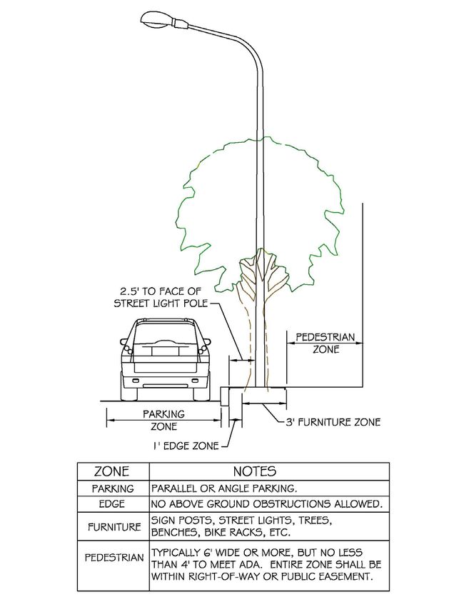
Table of Contents

   I. INTRODUCTION .............................................................................................................. 1

                 1.1 Policy ............................................................................................................................. 1

                 1.2 Definitions ..................................................................................................................... 1

                 1.3 General .......................................................................................................................... 4

   II. ROAD ELEMENTS ........................................................................................................... 6

                 2.1 Alignment ...................................................................................................................... 6

                       2.1.1 Horizontal Alignment...................................................................................6

                       2.1.2 Vertical Alignment ..................................................................................... 10

                 2.2 Road and Right-of-Way Widths ................................................................................12

                       2.2.1 Public Streets ............................................................................................. 12

                       2.2.2 Private Streets ........................................................................................... 13

                       2.2.3 Cluster Developments with Private Shared Driveways ....................... 14

                 2.3 Parking ........................................................................................................................17

                 2.4 Intersections ...............................................................................................................17

                       2.4.1 Allowable Intersection Types................................................................... 17

                       2.4.2 Corner Radii ............................................................................................... 18

                       2.4.3 Sight Distance ............................................................................................ 18

                       2.4.4 Corner Restrictions ................................................................................... 19

                 2.5 Clearance to Obstructions ........................................................................................21

                 2.6 Medians.......................................................................................................................21

                 2.7 Sidewalks ....................................................................................................................23

                 2.8 Street Lights ................................................................................................................23

                 2.9 Drainage......................................................................................................................23

                 2.10 Deceleration Lanes ..................................................................................................23

                       2.10.1 Right Turn Deceleration Lanes.............................................................. 24

                       2.10.2 Left Turn Deceleration Lanes ................................................................ 25

                 2.11 Bus bays ....................................................................................................................25

City of Chandler                                                         2                      Street Design and Access Control
January 2021                                                                                                            TDM #4
2.12 Bus Shelters ..............................................................................................................27

                2.13 Passenger Loading Zones (Autonomous Vehicles and Ride Sharing) ................28

   III. PAVEMENT STRUCTURAL DESIGN ............................................................................ 29

                3.1 Flexible Pavement ......................................................................................................29

                3.2 Rigid Pavement...........................................................................................................29

                3.3 Decorative Pavement.................................................................................................29

                3.4 Miscellaneous Pavement Standards........................................................................30

   IV. TRAFFIC CONTROL DEVICES ...................................................................................... 30

                4.1 Signing & Striping .......................................................................................................30

                4.2 Half Road Standards .................................................................................................33

                4.3 On-Street Parking with Bulb-Outs............................................................................33

                4.4 Accessible Parking Spaces.........................................................................................33

                4.5 Traffic Signals .............................................................................................................37

                4.6 Traffic Calming ...........................................................................................................37

   V. TRAFFIC IMPACT STUDIES ........................................................................................... 38

   VI. ACCESS MANAGEMENT .............................................................................................. 39

                6.1 Access Control ............................................................................................................39

                6.2 Location and Number of Access Points...................................................................39

                6.3 Emergency Access Requirements .............................................................................40

                6.4 Driveway Spacing and Storage.................................................................................41

                     6.4.1 Driveway Storage ...................................................................................... 42

                     6.4.2 Intersection Clearance ............................................................................. 42

                6.5 Driveway Widths ........................................................................................................44

                6.6 Curb Return radii .......................................................................................................44

   VII. ADA UPGRADE REQUIREMENTS ............................................................................... 45

                7.1 ADA Curb Ramps ........................................................................................................45

                     7.1.1 Standard Curb Ramps and Detectable Warning System Placement. 45

                     7.1.2 Asphalt Overlay Projects .......................................................................... 46

                     7.1.3 Capital Improvement Projects ................................................................ 46
City of Chandler                                                     3                     Street Design and Access Control
January 2021                                                                                                       TDM #4
7.1.4 Private Development Projects................................................................. 47
7.2 ADA Sidewalks ............................................................................................................48
VIII. PLAN SUBMISSION REQUIREMENTS ...................................................................... 51
List of Tables
TABLE 1 SUMMARY OF DESIGN STANDARDS 8
TABLE 2 MINIMUM WIDTH REQUIREMENTS FOR PRIVATE STREETS 13
TABLE 3 TYPICAL INTERSECTION CURB RETURN RADII 18
TABLE 4 DRIVEWAY WIDTHS (to-face-of-curb) 44
TABLE 5 DRIVEWAY CURB RETURN RADII (to-face-of-curb) 45
List of Figures
FIGURE 1 – BUBBLES FOR STREETS 9
FIGURE 2 – DESIGN AID FOR MAJOR INTERSECTION CROSS-SECTION 11
FIGURE 3 – CLUSTER CONFIGURATION OPTIONS 16
FIGURE 4 – TRIANGLE AREA 20
FIGURE 5 – TYPICAL MEDIAN NOSE LOCATION 22
FIGURE 6 - MEDIAN NOSE AT DRIVEWAY ENTRANCE 22
FIGURE 7 – PASSENGER LOADING ZONE TYPES 28
FIGURE 8 – RAILROAD MARKINGS 31
FIGURE 9 – STREET FURNITURE AND UTILITY LOCATIONS 35
FIGURE 10 – TYPICAL ON-STREET PARKING CROSS SECTION 36
City of Chandler 4 Street Design and Access Control
January 2021 TDM #4FIGURE 11 - MINIMUM TURNING RADII FOR TEMPORARY TURN-AROUND AND ON-SITE ROADWAYS PROVIDING EMERGENCY VEHICLE ACCESS 41 FIGURE 12 - DRIVEWAY SPACING ALONG ARTERIAL AND COLLECTOR STREETS 43 FIGURE 13 – CAPITAL IMPROVEMENT PROJECT CURB RAMP REPLACEMENT REQUIREMENTS 47 FIGURE 14 – PRIVATE DEVELOPMENT PROJECT CURB RAMP REPLACEMENT REQUIREMENTS 48 City of Chandler 5 Street Design and Access Control January 2021 TDM #4
I. INTRODUCTION

1.1 Policy
All streets within, and adjacent to developments shall be improved to City
Standards. The developer is responsible for all costs associated with the required
improvements.

Functional classifications for principal arterials and major or minor arterial streets
are contained in the City’s latest Transportation Master Plan.               Functional
classifications for other streets shall be determined by the Public Works & Utilities
Director or his designee.     Minimum required rights-of-way widths shall be in
accordance with the City Code.

A traffic analysis by a traffic consultant is required for proposed developments
determined by the Public Works & Utilities Director or his designee to have a large
impact on the street system.       The required elements of the traffic analysis are
contained in Section 5 Traffic Impact Studies. The developer is responsible for the
costs of the analysis as well as the costs for implementing the recommendations of
the analysis.

Improvements to pedestrian design facilities shall meet the accessibility
requirements of the Americans with Disabilities Act (ADA).

1.2 Definitions
For the purposes of this manual, the following definitions are used:

Alley: A public thoroughfare that affords only a secondary means of access to
abutting property.

Developer: The individual, firm, corporation, partnership, association, syndicate,
trust, or other legal entity that files the application and initiates proceedings for the
development and/or subdivision of land in accordance with the City Code and said
developer need not be the owner of record of said land.

Easement: A grant by the owner for the use of specified land by the public, a

City of Chandler                           1            Street Design and Access Control
January 2021                                                                    TDM #4
corporation, or persons, for specific uses and purposes and so designated and
recorded in the county recorder's office.

Intermediate intersection: The intersection of any collector or local street or major
driveway with any major or minor arterial functioning as the through roadway.

Major intersection:     The intersection of any principal arterial (freeway or
expressway) major or minor arterial with any major or minor arterial.           These
intersections are typically found at the section corners as the section-line roadways
intersect.     The intersection of two principal arterials normally requires an
interchange.

Major generator: Any development (commercial, industrial, residential, or mixed
use) which generates more than 5,000 trips per weekday.

Major driveway:      Any driveway, which intersects a major or minor arterial and
serves the main parking area of a major generator, with all movements permitted.

Minor driveway: Any non-major driveway, which provides access to a major or
minor arterial. The access can be full, i.e., all movements permitted, or with certain
movements restricted.

Median:      A raised or flush area designed to separate and control vehicular
movement.

Pedestrian Way: A public walk dedicated entirely through a block from street to
street and/or providing access to a school, park, recreation area or shopping
center.

Right-of-Way:      Any land which by deed, conveyance, agreement, easement,
dedication, usage, zoning condition, process of law or other means is reserved for
or dedicated to the general public for street, highway, alley, public utility, or
pedestrian walkway purposes and accepted by the City.

City of Chandler                            2         Street Design and Access Control
January 2021                                                                  TDM #4
Street: Any existing or proposed street, avenue, boulevard, road, bridge, viaduct, or
easement for public vehicular access or a street shown in a plat duly filed and
recorded in the county recorder's office. A street includes all land within the street
right-of-way whether improved or unimproved and includes such improvements as
pavement, shoulders, curbs, gutters, sidewalks, parking spaces, bridges, viaducts
and traffic-control devices.

   1) Arterial street: A major street of exceptional continuity that is intended to
       carry the greater portion of through traffic from one area of the City to
       another and is generally positioned at one-mile intervals. Major and minor
       arterials are designated in the current City Transportation Plan.

   2) Collector street: A street designed with the primary purpose of collecting and
       distributing traffic, to and from, arterial streets.

          a. Industrial collector: A collector street serving commercial, industrial or
              other     land uses expected to generate high traffic volumes or
              substantial heavy truck traffic.
          b. Residential    collector:   A   collector   street   serving   predominantly
              residential land uses.

   3) Local street: Typically, a street of limited continuity with the primary purpose
       of serving only those lots, which are adjacent.

   4) Cul-de-sac: A short local street having but one end open for vehicular traffic,
       the opposite end being terminated with a permanent turnaround.

   5) Private street: A street not owned or maintained by the City.

   6) Public street: A street owned and maintained by the City.

   7) Driveways:

          a) Commercial driveway: Access for retail, office, high density residential

City of Chandler                             3             Street Design and Access Control
January 2021                                                                       TDM #4
or government/community service building.
b) Industrial driveway: Access for large industrial, office park, mixed use,
or warehouse developments, which may also accommodate heavy
truck movements.
c) Residential driveway: Access to single-family residence from local or
collector street only. Access from an arterial street is not allowed in
the city.
d) Private shared driveway: driveway serving more than one lot.
e) Parking lot access way: Access to and circulation among parking areas
within an integral apartment or townhouse complex
1.3 General
The City has adopted Maricopa Association of Governments (MAG) Standard
Specifications and Standard Details. Several of those have been modified, as
shown in the City’s Standard Details and Specifications. MAG specifications and
details shall be used except where corresponding specifications or details have
been adopted by the City.
The design standards presented within this manual should be treated as minimum
standards. The American Association of State Highway and Transportation Officials
(AASHTO) has published several design standard policies. Should a conflict
between this manual and an AASHTO policy occur, the City’s standards or policies
shall apply.
All traffic control signs and pavement markings shall be in accordance with the
Manual on Uniform Traffic Control Devices (MUTCD) prepared by the U.S.
Department of Transportation and the City of Chandler's Standard Details. All
traffic control materials used shall conform to Arizona Department of
Transportation Standard Drawings and Specifications (ADOT) unless otherwise
noted.
City of Chandler 4 Street Design and Access Control
January 2021 TDM #4The City Engineer may promulgate additions or revisions to the standards as needs arise. Each successive phase of a development must satisfy all of the requirements given within this manual. In addition, all arterial street improvement requirements must be satisfied with the first phase. In the case of large developments, the City reserves the right to require satisfaction of collector street improvement requirements with the first phase. Right-of-way width and required improvements for each street classification are found in the City Standard Details. Newly constructed and reconstructed arterial streets are to be designed to accommodate on-street bike lanes, except where the necessary street width is not feasible because of right-of-way or existing development constraints. Bike lanes are to be marked on collector streets selected by City staff in consultation with the developer or neighborhood representatives. A brief summary of the City's design standards is shown in Table 1. Each of the design standards is discussed in detail in the following sections. City of Chandler 5 Street Design and Access Control January 2021 TDM #4
II. ROAD ELEMENTS

2.1 Alignment

2.1.1 Horizontal Alignment
The minimum horizontal centerline radii shown in Table 1 are for normally crowned
streets. The use of super-elevation to reduce the minimum horizontal centerline
radii is prohibited on all streets except arterials. Super-elevation may be used on
arterial streets upon approval of the Public Works & Utilities Director or his
designee, providing the street cross-slope does not exceed 4.0%. The City reserves
the right to modify the design speeds shown in Table 1 for arterial and collector
streets when justified by special circumstances where overall safety is not
compromised.

For special cases where the minimum tangent lengths shown in Table 1 cannot be
achieved, the Public Works & Utilities Director or his designee may approve
reduced requirements providing that sight distance and overall safety are not
compromised. In general, intersection tangents will not be required where the radii
for both streets are 400 feet or greater.
All street intersections with arterials or major collectors shall be at 90 degrees. All
other street intersections shall not vary from 90 degrees by more than ±15 degrees.

Horizontal curves are not required when the necessary alignment change can be
accomplished with a taper. Taper requirements are given below:

       For Redirection of Through Lanes:

              For Speeds ≥ 45 MPH,      L= SxW
              For Speeds ≤ 40 MPH,      L=       WS2
                                                 60

       For Entry Into Turn Bays:

              L = SxW              Where         L =   Taper Distance in Feet
                    3                            S =   Speed Limit in Miles Per Hour
                                                 W=    Offset Distance in Feet

City of Chandler                             6           Street Design and Access Control
January 2021                                                                     TDM #4
Length, L = 100 feet minimum, and should be extended as required by
sight distance conditions.
Please note that these taper requirements also apply when narrowing the
improved street width, and may apply to widened sections if traffic lanes are being
offset.
Desirable cross-street intersection spacing along arterial streets is at quarter-mile
intervals. Intermediate intersections may be located a minimum of one-eighth mile
from the nearest major intersection with a maximum of five intersections
permitted per mile of arterial street. Desirable minimum distances between cross-
street intersections are 125' along local streets, 250' along collector streets with no
raised median, and 400' along collector streets with a raised median.
The maximum allowable block length is 1,200 feet and, generally, the maximum
allowable length of cul-de-sac is 400 feet, measured from the intersection of the
right-of-way lines at the throat to the extreme end of the bulb. Generally, "dog-leg"
type cul-de-sacs are discouraged.
Bubbles are normally constructed at all two-legged intersections on local streets,
see Figure 1.
City of Chandler 7 Street Design and Access Control
January 2021 TDM #4TABLE 1
SUMMARY OF DESIGN STANDARDS
ITEM ARTERIAL COLLECTOR LOCAL
Design Speed (mph) 55 40 25
Minimum Horizontal 1,800 700 (with 250 (with
Centerline Radius (ft.) driveways) driveways)
400 150 minimum
minimum (no (no driveways)
driveways)
Minimum Tangent Length
at Intersections (ft.) 550 300 150
(Measured from the intersection
center line )*
Cross-Slope (%) 2.5-3.0 2.0-3.0 2.0-3.0
Maximum Longitudinal Slope
Change Not Requiring a
1.0 2.0 2.0
Vertical Curve (%)
Stopping Sight Distance (ft.)
Height of eye 3.5 ft., and
Object height 6 in. 495 305 200
Minimum Vertical Curve
Length, Crest (ft.) 220 x A 80 x A 20 x A
A=Algebraic Difference in
Grades (%)
City of Chandler 8 Street Design and Access Control
January 2021 TDM #4Minimum Vertical Curve 130 x A 70 x A 30 x A
Length, Sag (ft.)
A=Algebraic Difference in
Grades (%)
*Not required on a local or collector street approach with a centerline radius ≥ 400
feet or more.
FIGURE 1 – BUBBLES FOR STREETS
R
44
.5
50'
'R
55' R
R
50.5'
50
'R
5' R
44.
City of Chandler 9 Street Design and Access Control
January 2021 TDM #42.1.2 Vertical Alignment
Variances to the slope requirements shown in Table 1 may be approved by the
Public Works & Utilities Director or his designee if the following conditions are met:
1) The variance must be justified on an engineering basis,
2) No alternatives are available,
3) Safety is not compromised,
4) Drainage problems will not be created, and
5) The variance benefits the City.
The minimum vertical curve lengths shown in Table 1 are preferred values. The
Public Works & Utilities Director or his designee may approve shorter lengths if
justified by a detailed analysis and if safety is not compromised.
A design aid for street cross-slopes at intersections along arterial streets and along
major collector streets is presented in Figure 2. This figure should be treated as a
conceptual guideline, not an absolute requirement. The objective of this design aid
is to provide for the smooth flow of traffic through intersections. The street
longitudinal and cross slope requirements shown in Table 1 do not apply within the
intersection, except for the maximum longitudinal slope change not requiring a
vertical curve. However, positive drainage must still be achieved.
City of Chandler 10 Street Design and Access Control
January 2021 TDM #4FIGURE 2 – DESIGN AID FOR MAJOR INTERSECTION CROSS-SECTION
2.5%
50' (TYP.)
2.0%
1.5%
1.0%
0.5%
0.5%
2.5%
2.0%
1.5%
1.0%
0.5%
0.5%
0.5%
1.0%
1.5%
2.0%
2.5%
0.5%
1.0%
1.5%
2.0%
2.5%
City of Chandler 11 Street Design and Access Control
January 2021 TDM #42.2 Road and Right-of-Way Widths
In general, right-of-way widths shall follow City Standard Details C-203 – C-223.
2.2.1 Public Streets
Arterials
All newly constructed or reconstructed arterial streets shall be marked with bike
lanes. Arterial street bike lanes shall generally be five feet wide, not including any
part of an adjacent gutter pan. Vehicle lane widths on a six-lane arterial street shall
be 12 feet for lanes next to the median and next to the bike lanes, and 11 feet for
the center through lane in each direction of flow. See City Standard Detail C-619.
For remarking of existing arterial streets, lane widths are as follows:
• A two-way left turn lane shall be at least 10 feet wide, 10.5 feet preferred.
• A vehicle through lane shall be at least 10.5 feet wide, 11 feet preferred.
• A vehicle through lane next to a median curb or bike lane shall be at least 11
feet wide, 12 feet preferred.
• A bike lane shall be at least four feet wide, but the bike lane shall be
increased to a width of five feet where possible with the preferred vehicle
lane widths listed above. Gutter pans shall not be included in the
measurement of bike lane widths.
Along existing arterial streets too narrow to provide bike lanes, the outside lane will
be made as wide as possible by using the minimum vehicle lane widths described
above for the center and inside lanes.
Collectors
A 45’ collector road (to back-of-curb) may be striped in a number of ways to
accommodate vehicular traffic, bikes, and on-street parking. Three typical
configurations are shown below:
City of Chandler 12 Street Design and Access Control
January 2021 TDM #4• An 11’ two-way left turn lane (TWLTL), one 11’ travel lane and 4’ bike lane (as
measured to the lip-of-gutter) in each direction.
• A straight centerline with a 14’ travel lane and 8’ parking lane (as measured to
the face-of-curb).
• A straight centerline with a 12’ travel lane, a 3.5’ hatched buffer, and 5’ bike
lane (as measured to the face-of-curb) in each direction.
2.2.2 Private Streets
Private streets are subject to all of the requirements for public streets except for
the minimum allowable widths shown in Table 2. Continuous through streets
cannot be comprised of both public and private roadway sections.
Street name signs, City Standard Details C-601 and C-605, shall be installed at all
private street intersections.
TABLE 2
MINIMUM WIDTH REQUIREMENTS FOR PRIVATE STREETS
Road Width Private Street Parking
(to back-of-curb, ft.) Tract Width (ft.)
25 33 None allowed *
29 37 One side only *
35 43 Both sides
1) Refer to Section 2.3 for applications of these standards.
2) Refer to Section 2.7 for sidewalk requirements. The width shown assumes 4 ft.
sidewalk on both sides. Tract width requirements with a 5 ft. sidewalk increase
by 2 ft. to 35, 39 and 45 feet, respectively.
3) *Refer to Fire Department Detail FD111 for Fire Lane signing and marking
requirements.
City of Chandler 13 Street Design and Access Control
January 2021 TDM #42.2.3 Cluster Developments with Private Shared Driveways
Cluster developments with a private shared driveway shall adhere to the
configuration options shown in Figure 3 and the requirements shown below:
Design Standards
a. Private driveway specifications shall be per City Standard Detail C-214.
Minimum width is 24'.
b. Driveway entrance per MAG Standard Detail 250. Additional sidewalk easement
may be required.
General Requirements
a. Solid waste collection will be picked up only on private or public streets in a
designated area. For private street widths less than 29', an additional (off street)
designated area will be required.
Utility Requirements
a. Standard water, sewer and electric locations are shown on City Standard Detail
C-214.
b. Separate easements or P.U.E.'s are required for water meters, fire hydrants,
transformers, streetlights, utility pedestals, etc.
c. All dry utilities shall be joint trenched within the 24' P.U.E.
d. Some type of private streetlights are to be provided.
e. Water shall be 6" minimum on a private drive.
f. GPS coordinates shall be provided for all bends in water and sewer service lines.
Planning and Platting Requirements
a. The 6-pack cluster options shown are the standard approved lot configurations.
Other configurations may be approved by the Public Works & Utilities Director
or designee.
b. Each private driveway shall be designated as a tract and responsibility dedicated
appropriately.
c. Easements required over private driveway (tract) shall be dedicated
appropriately in this order:
1. Water & Sewer Easement (to City of Chandler).
City of Chandler 14 Street Design and Access Control
January 2021 TDM #42. Public Utility Easement
3. Cross Access Easement
4. Drainage Easement
Fire Department Requirements
a. No parking will be permitted on private driveway. Visitor parking must be
provided in designated areas.
b. See City Fire Department Detail FD-111 and/or FD-112 for fire lane signage and
parking restrictions on a private street.
c. Private driveway shall have a turnaround (hammer head) as shown on Cluster
Option 1 or when Cluster Option 2 depth exceeds 150'. This supersedes City
Fire Department Detail FD-141 requirements.
City of Chandler 15 Street Design and Access Control
January 2021 TDM #4FIGURE 3 – CLUSTER CONFIGURATION OPTIONS City of Chandler 16 Street Design and Access Control January 2021 TDM #4
2.3 Parking
This section deals specifically with on-street parking on private residential streets.
It clarifies the requirements that will allow use of a 25-foot wide private road within
developments, as specified in Table 3 of Section 2.2.2. The rules that follow do not
apply to apartments, or developments similar to apartments, where all parking is
already commonly shared. Exceptions to this rule may also be permitted in very
large lot (greater than 90’ lot frontage) subdivisions where circular or very long
driveways can accommodate large number of visitors parking privately on the same
lot.

A 25-foot wide road requires that ‘No Parking’ be permitted on both sides of the
street. In such instances, all residential developments must have adequate visitor
parking within a convenient distance of individual lots to ensure that drivers do not
park on-street. This ‘No Parking’ requirement allows for safe access by emergency
vehicles, and provides for two-way circulating traffic.

The City Code Section 47-14 currently specifies that “The minimum allowable width of
the private streets will be determined by the City Engineer based on projected traffic
volume and availability of off-street parking.” As a general rule, a minimum of 10
parking spaces or 0.25 spaces/unit, whichever is greater, will be required for on-site
visitor parking before a 25-foot wide private road will be considered. Visitor parking
spaces are defined as common-area spaces, and are in addition to the parking for
individual units (i.e. driveway parking). These commonly shared parking spaces
may be grouped together for convenience, but must be evenly spaced throughout
the site to minimize the walking distance to individual lots.

2.4 Intersections

2.4.1 Allowable Intersection Types
Design types permitted for major intersections on arterial streets are as follows:

       • Basic crossing with four legs.
       • T-intersection with three legs.
       •   Roundabouts

City of Chandler                           17             Street Design and Access Control
January 2021                                                                      TDM #4
No five- or six-leg intersections are permitted.
2.4.2 Corner Radii
Curb return radii requirements are shown on Table 3. Deviations from this
standard will required City staff approval.
TABLE 3
TYPICAL INTERSECTION CURB RETURN RADII
Typical Radii
Type of Intersection (Face-Of-Curb), ft.
Arterial-Arterial, Arterial-Collectors, and 30
Industrial Roads
Arterial-Locals*, Collector-Collectors, and 25
Collector-Locals
Local-Locals 20
* For gated entries, refer to Table 6A for driveways.
2.4.3 Sight Distance
Corner sight distance requirements at intersections are given on City Standard
Details C-246 and C-247. An additional requirement from the Zoning Code, known
as the "triangle area,” is shown in Figure 4. There is an additional engineering
requirement for traffic control device visibility noted on Figure 4.
No obstructions of any type over 18 inches high, including landscaping, are allowed
within 1 foot of the back-of-curb.
Stopping sight distance is the minimum sight distance allowable for all intersection
approaches. Minimum stopping sight distances are shown in Table 1 for flat
terrain. Roadways on grade will increase or decrease these distances, and in such
City of Chandler 18 Street Design and Access Control
January 2021 TDM #4cases, references such as the American Association of State Highway Transportation
Official’s (AASHTO) policies and guidelines for roadway design should be consulted.
Three types of movements for traffic entering a major street from a minor side
street or driveway result in three different sets of sight distance requirements:
1. Right turns from the minor street onto the major street
2. Left turns from the minor street onto the major street
3. Left turns into the intersection or access point from the major street
Sight-distance requirements for entering arterial or collector streets are shown on
City Standard Detail C-246. Heights of buildings, walls, landscaping and other
similar obstructions should be restricted within the sight triangles. Sight distance is
measured from a driver’s eye height of 3.5 feet to an approaching target 4.25 feet
high.
Along local or collector streets with residential frontage where motorists can expect
frequent conflicts with vehicles entering or exiting driveways, a minimum sight
distance of 200 feet is required, as illustrated in City Standard Details C-247 and C-
248. As explained above for arterial and collector streets, heights of obstructions
should be restricted within the sight triangles to provide a clear field of vision from
a driver’s eye height of 3.5 feet to an approaching target 4.25 feet high.
2.4.4 Corner Restrictions
The City’s Municipal Code Chapter 48-10.2 (Public Works - Subdivision) specifies a range of
triangular cutoffs for the corner property line at intersections. Additionally, Figure 4 below
requires that the 30’ x 30’ area be kept clear of visual obstructions between 2’ and 6’ in
height.
City of Chandler 19 Street Design and Access Control
January 2021 TDM #4FIGURE 4 – TRIANGLE AREA City of Chandler 20 Street Design and Access Control January 2021 TDM #4
2.5 Clearance to Obstructions
Streetlight poles, utility poles, and similar obstructions are not allowed within 1 foot
of a sidewalk. Streetlight poles are not allowed within 2.5 feet of the back-of-curb.
Utility poles and similar obstructions are not allowed within 5.5 feet of the back-of-
curb, but obstructions may be located as close as 2.5 feet from back of curb when
adjacent to deceleration lanes, parking lanes, right turn lanes or bus bays. All
dimensions above refer to face-of-pole.

2.6 Medians
Raised medians shall be installed on all new arterial streets complete with curbs,
pavers and landscaping, unless otherwise specified. Flush medians may be
installed on arterial reconstruction projects where flush medians currently exist,
with approval of the Public Works & Utilities Director or his designee.

Median breaks shall generally be constructed at one-eighth, one-quarter, and one-
half mile spacing from major intersections.        All other median breaks must be
justified by a traffic study and approved in writing by the City Transportation Engineer.
Please refer to Section 6.4 for details on other access spacing. Median breaks will not
be allowed in medians of less than 14 feet in width.

Raised median noses shall be designed as shown in Figures 5 and 6. Typical
median designs are shown in City Standard Details C-225, C-226, and C-227.
Median terminations at midblock locations not at a driveway or intersection shall
be semi-circular.

When designing oversized raised medians that allow for future widening from four
lanes to six lanes, the left turn bays shall be constructed at their ultimate locations.

City of Chandler                           21           Street Design and Access Control
January 2021                                                                    TDM #4
FIGURE 5 – TYPICAL MEDIAN NOSE LOCATION

               FIGURE 6 - MEDIAN NOSE AT DRIVEWAY ENTRANCE

City of Chandler                     22        Street Design and Access Control
January 2021                                                           TDM #4
2.7 Sidewalks Sidewalks shall be provided along all arterial, collector and local streets as shown on Typical Cross Section Standard Details C-203 – C-222. Typical minimum width is 6 foot for arterials and 5 foot for collectors and locals. In areas with high pedestrian volumes, wider sidewalks may be required. Construction shall be per MAG Standard Detail 230, and may be modified to 4 foot minimum provided that, per ADA, a 5 foot by 5 foot passing area is provided every 200 feet to allow wheelchairs to pass on all sidewalks. Driveways and other connecting sidewalks may be used to provide the passing area, as long as the cross-slope is less than 2%. 2.8 Street Lights Please refer to the City’s Street Light Design (Technical Manual #6). 2.9 Drainage Valley gutters are not allowed to cross arterial streets under any circumstances. Six- foot wide gutters (per MAG Standard Detail 240) are to be used where there is stop control for through traffic and eight-foot (mid-block) valley gutters (per City Standard Detail C-233) are to be used where there is no stop control. For inlet options and requirements, refer to City Drainage Policies and Standards, TDM #3. Storm drains are normally installed whenever the 10-year design storm flows cannot be contained within the top-of-curbs. However, the installation of 7-inch vertical curb instead of the standard 6-inch vertical curb may eliminate the need for storm drains. The use of 7-inch vertical curb requires special approval of the Public Works & Utilities Director or his designee and may only be installed on short sections of street near the drainage inlets. 2.10 Deceleration Lanes Left turn and right turn lanes shall be provided on all approaches to major (arterial- arterial) intersections as shown in City Standard Detail C-223. Left turn lanes shall be provided on all median breaks, and right turn lanes shall be provided where warranted by projected traffic demands (per Section 2.10.1). City of Chandler 23 Street Design and Access Control January 2021 TDM #4
Where turn lanes are constructed, length of storage lanes shall be a minimum of
100 feet.    Turn lane lengths at intersections for which traffic signals may be
warranted shall be designed to accommodate 15 to 20-year traffic demands with
less than a 5-percent probability of overflow during peak flow periods. Design
guidelines for deceleration lanes on arterial streets are presented in City Standard
Details C-224, C-225, C-226, C-227 and C-231. In most cases, it is preferable to
provide more turn-lane storage rather than longer taper lengths.
Where the demand warrants and cross-sectional widths are available on both the
intersecting streets, dual right-turn and/or left-turn lanes can be incorporated.

If additional right-of-way is required above the normal right-of-way requirement in
order to construct a deceleration lane or the sidewalk associated with a
deceleration lane, it is the developer’s responsibility to provide it. Normally, the
right-of-way required will extend a minimum of 4 feet back of the sidewalk.

2.10.1 Right Turn Deceleration Lanes
A right turn deceleration lane shall be provided at cross streets and driveways
when projected right turns into the site exceed 40 vehicles for a typical peak hour.

Where successive driveways are less than 400 feet apart (nearest edge to nearest
edge), a continuous right turn lane rather than separate right turn lanes shall be
constructed. Where a driveway warranting provision of a right turn deceleration
lane is located less than 450 feet in advance of an arterial cross street, a continuous
right turn lane rather than separate right turn lanes shall be constructed.

Driveways are not permitted within the taper itself.          All driveways shall be
contained within the fully developed deceleration lane itself, including the curb
returns.    The design of a continuous right-turn deceleration lane should not
continue through a full-access intersection or driveway entrance (median break).

The City Transportation Engineer on a case-by-case basis may waive the right turn
deceleration lane requirement.

City of Chandler                          24           Street Design and Access Control
January 2021                                                                   TDM #4
2.10.2 Left Turn Deceleration Lanes
Left turn deceleration lanes are required as specified in Section 2.10. On arterial
streets without a median (roadways not yet upgraded to City standards), temporary
widening shall be constructed to accommodate a left turn lane and through lane
redirection tapers as shown in City Standard Detail C-229.

2.11 Bus bays
1. Placement of Bus Bays.

       A. All Bus bay locations must have prior written approved of the City’s
          Transportation Engineer and must be consistent with the City’s
          Transportation Master Plan.

       B. Bus bays will generally be placed at one mile intervals along arterial
          streets with existing or planned bus routes, adjusted as necessary to
          ensure that boarding and de-boarding will be convenient for service to
          abutting land uses. Additional bus bays, if warranted, may be spaced at
          one-half mile intervals, but in no case spaced less than one-quarter mile
          apart.

       C. Generally bus bays should be installed only at signalized intersections.

       D. Bus bays should be located at the far side of street intersections (on
          departures from the intersection) and within two hundred feet (200’) of
          signalized intersections.

       E. Bus bays should not be installed at mid-block locations.

       F. Bus bays may be integrated with right-turn deceleration lanes. The
          integrated design will provide a constant lane cross-slope with no valley
          gutter existing or constructed between the through travel lanes and the
          combination bus bay/ deceleration lane.

City of Chandler                          25           Street Design and Access Control
January 2021                                                                   TDM #4
G. Bus bays should be located at route transfer points and layover locations
at the end of bus routes.
H. Bus bays should be located at stops with high peak period passenger
boardings, or at stops with a high proportion of wheelchair or bicycle
boardings.
I. Right-of-way impacts and utility relocations should be avoided or
minimized when determining bus bay locations.
J. Bus bay locations will be prioritized and programmed in the City’s Capital
Improvements Program based on the following criteria: average daily
traffic volumes, street lane capacity, frequency of bus service and average
number of passenger boardings.
K. The City will require dedication of right-of-way from new developments
along existing and planned transit routes for construction of bus bays and
associated landing and shelter pads.
2. Design and Construction of Bus Bays
A. Bus Bays shall be constructed of concrete and designed in accordance
with City of Chandler Standard Details and Specifications C-230 when not
integrated with a deceleration lane and with C-231 when integrated with a
deceleration lane.
B. Bus bays should be incorporated into the design and construction of
larger arterial street and intersection improvement projects to reduce
costs.
C. All bus bays should include a concrete pad of sufficient dimensions
located behind the adjacent sidewalk to accommodate a passenger
shelter, bench, trash receptacle and advertising/information kiosk.
City of Chandler 26 Street Design and Access Control
January 2021 TDM #42.12 Bus Shelters
A. Advertising at bus stops located on arterial streets areas should be
permitted to offset the costs of installing and maintaining passenger
shelters and associated fixtures.
B. Advertising revenues will be used to offset transit operating costs.
C All new passenger shelters should be lighted or located in proximity to an
existing streetlight.
D. Where irrigation is available, landscaping and shade trees should be
provided in proximity to the shelter pad to increase shade to the
passenger waiting area.
E. The design of developer installed bus shelters and associated fixtures
require prior written approval of the City Engineer before construction.
Shelter ownership, long-term maintenance responsibilities, and
replacement cost due to damage are primary considerations.
F. All new bus stops shall meet the accessibility requirements set forth
under the Americans with Disabilities Act (ADA).
G. For existing bus stops, any necessary upgrades to meet ADA
requirements shall occur with adjacent projects including mill and overlay,
private development and CIP.
H. Bus shelters should only be installed along streets served by a transit
route.
City of Chandler 27 Street Design and Access Control
January 2021 TDM #42.13 Passenger Loading Zones (Autonomous Vehicles and Ride Sharing)
This section deals specifically with passenger loading zones intended for on-site
passenger drop-off and pick-up scenarios, but may also be applied to public rights-
of-way with the approval of the City Transportation Engineer. Please reference City
Zoning Code Section 35-1808 and Chandler Building Code for other requirements
or allowances.
Generally, there are two types of passenger loading zone scenarios provided to
accommodate traffic flow, travelled way width restrictions and other site or design
considerations. For Type ‘A’ both the vehicle pull-up space and access aisle are
outside the travelled way, while Type ‘B’ only the access aisle, as shown on Figure 7
below.
FIGURE 7 – PASSENGER LOADING ZONE TYPES
Further guidelines are listed below and presented on City Standard Detail C-261.
This section provides general guidance on a variety of curbing and accessible ramp
City of Chandler 28 Street Design and Access Control
January 2021 TDM #4options, some of which are shown, that may be tailored to meet the needs of each
site.
1) Access aisles shall be marked as shown and must connect to an accessible
route to the building.
2) Access aisles shall be at the same level as the vehicle pull-up space they
serve and shall not overlap the travelled way.
3) Access aisles and pull-up spaces shall have slopes no steeper than 2% in any
direction.
4) Passenger loading zones shall be signed as shown.
5) Bollards or other types of barriers may be used adjacent to loading zones as
long as minimum ADA widths are provided.
6) All single loading zones shall be accessible. For multiple and continuous
loading zones, one accessible loading zone shall be provided every 100 feet.
III. PAVEMENT STRUCTURAL DESIGN
3.1 Flexible Pavement
City Standard Details C-203 through C-222 for street cross-sections also include
notes referring to the appropriate City Standard Detail for asphaltic pavement
thickness and the appropriate MAG Standards for material requirements.
3.2 Rigid Pavement
Rigid pavements, such as Portland cement concrete, are generally not used for City
streets. If rigid pavements are used, each design must be approved by the Public
Works & Utilities Director or his designee on an individual basis.
3.3 Decorative Pavement
The use of interlocking paving blocks in roadways and medians must be approved
by the Public Works & Utilities Director or his designee. When approved, they shall
be installed in accordance with MAG Standard Detail 225 using pattern and stone
per City List of Approved Products. In addition a minimum of 25 paving blocks of
the type installed must be deposited free of charge at the City's maintenance yard
for future City maintenance operations.
City of Chandler 29 Street Design and Access Control
January 2021 TDM #4The use of decorative concrete may be approved optionally by the Public Works & Utilities Director or his designee. 3.4 Miscellaneous Pavement Standards For cases where the full depth of base course cannot be constructed due to insufficient cover over existing facilities, the City reserves the authority to approve equivalent alternate designs if justified. The minimum pavement cross-sectional requirement for temporary turnarounds, which are constructed at project phase lines, is 6 inches of aggregate base course over 6 inches of subgrade; see MAG Standard Specifications Sections 301, 310 and 702. If the temporary turnaround is constructed at a project boundary, a surface course of 2 inches of asphaltic concrete is required in addition to the base and subgrade noted above; see MAG Standard Specifications Sections 321 and 710, without lime. Temporary pavement cross-sections shall consist of 2 inches of asphaltic concrete over 6 inches of aggregate base course over 6 inches of subgrade, see the same MAG Standard Specifications sections noted above. IV. TRAFFIC CONTROL DEVICES 4.1 Signing & Striping Yield signs may be placed at intersections with no acceleration lane where the safe entry speed is greater than 10 MPH. All yield sign use and placement shall be by the approval of the Public Works & Utilities Director or his designee. All signs must be manufactured of “ASTM D-4956-04 Type IV Sheeting” which will be attached to the standard signage aluminum plates. Sign imaging shall be in compliance with the reflective sheeting manufactures matched component system. Sign imaging shall consist of an acrylic based electrocut film or silk screened using inks (depending on the quantity of signage) with standard highway colors. City of Chandler 30 Street Design and Access Control January 2021 TDM #4
Barricades, MAG Standard Detail 130 Type "B,” are required at all dead end streets
and street stub-outs, except cul-de-sacs. An end of road marker (18"x18"), MUTCD
OM4-3 (retro-reflective red diamond panel), spaced on 5 foot center along the
barricade are required. A turn-around area is also required (see Sections 6.3 of this
manual).

Deceleration and right-turn lanes are signed and striped in accordance with Detail
C-620 of the Standard Details and Specifications Document.

Speed limit signs, MUTCD R2-1, are installed on all local and collector streets at
approximately 100 to 200 feet from arterial intersections. Speed limit sign locations
on arterial streets are shown in Detail C-621 of the Standard Details and
Specification Document. The posted speed limit for local streets is 25 mph. The
posted speed limit for collector and arterial streets is determined by the City
Transportation Engineer, based upon individual circumstances. No parking signs,
MUTCD R8-3a, are 24” x 24” on arterials and 18” x 18” on all other streets.

Arterial and collector signage and striping standards are shown on Detail C-600
through Detail C-623. Reflective markers are required on all arterial streets. On
collector streets reflective markers are required only along street sections with
unusual conditions, such as: intersection approaches where through lanes converge
after the end of a median or left turn lane.       Where conditions require use of
reflective markers, the markers are to be installed from a point 500 feet or more in
advance of the conditions to a point 500 feet or more beyond the conditions.
Pavement markers shall be prismatic reflectors only.

Typical median signage is shown on Detail C-600 of the Standard Details and
Specifications.

Typical railroad crossing signage and striping is shown on Figure 8.

                        FIGURE 8 – RAILROAD MARKINGS

City of Chandler                          31           Street Design and Access Control
January 2021                                                                   TDM #4
Developments are required to supply and install sign posts at all intersections for new stop signs and street name signs. Public street name signs will be installed by the City after payment of the prevailing fees by the developer. This is the only case where the City will perform any work associated with a development. Private street name signs are the responsibility of the developer. Signal conduit, 4-inch diameter schedule 40 PVC with detectable mule tape and with ADOT No. 7 pull boxes, is installed at all legs of arterial intersections where median breaks are present, including arterial-arterial intersections. See ADOT Standard Detail T.S. 1-4 for No. 7 pullbox. Traffic signal interconnect conduit and fiber are required on all arterial roads, shall be per requirements in TDM #5, Traffic Signal Design Manual. City of Chandler 32 Street Design and Access Control January 2021 TDM #4
4.2 Half Road Standards
Generally, developments are required to construct all full roads internal to the
development, and half-roads bordering the development.

A half-road shall be a minimum of 24 feet from face-of-curb to the edge of
pavement.

For arterial and collector half-roads with a raised median, the half-road shall
include the full raised median, and one through lane in the opposing direction.
Arterials with flush medians and two-way-left-turn lanes should be treated in the
same manner.

All typical road infrastructure requirements (such as street lights, landscaping,
irrigation, sidewalk, etc.) shall apply to half-roads. There may be other additional
improvements, as deemed necessary by the Public Works & Utilities Director or his
designee.

4.3 On-Street Parking with Bulb-Outs
The following requirements shall apply for all on-street parking using bulb-outs. See
City Standard Detail C-215 for the typical street cross-section. The standard allows
for both the normal crown and valley gutter option; however, additional drainage
considerations will be necessary when not using a valley gutter.

Parallel parking spaces shall be 8’ x 22’. Angle parking spaces shall be 9’ x 19’
(measured perpendicular to face-of-curb) at a standard angle of 60 degrees. See
City Standard Detail C-260 for further details and requirements.
Figure 9 and 10 illustrate the placement of trees, street lights, utility boxes, etc. See
Fire Department Standard Details for further requirements, and also Downtown
Streetscape Guidelines for additional recommendations.

4.4 Accessible Parking Spaces
Per the Proposed Rights-of-way Access Guidelines (PROWAG) R309, accessible
parking spaces are required whenever “marked” on-street parking spaces are
provided on a City block. The number of required spaces is 4% of the total number
of spaces on that block, with a minimum of one per block.

City of Chandler                           33           Street Design and Access Control
January 2021                                                                    TDM #4
PROWAG requires access aisles only in specific situations where sufficient sidewalk
width is provided. (See PROWAG R309) For parallel parking, an available sidewalk
width of 14’ or more will require an access aisle. When used, the accessible spaces
shall conform to Standard Detail C-260, Page 2.

For existing designated on-street parking spaces, any necessary upgrades to meet
ADA requirements shall occur with adjacent projects including mill and overlay,
private development and CIP.

City of Chandler                        34          Street Design and Access Control
January 2021                                                                TDM #4
FIGURE 9 – STREET FURNITURE AND UTILITY LOCATIONS

City of Chandler                   35        Street Design and Access Control
January 2021                                                         TDM #4
FIGURE 10 – TYPICAL ON-STREET PARKING CROSS SECTION

City of Chandler                  36        Street Design and Access Control
January 2021                                                        TDM #4
4.5 Traffic Signals
If new development requires the relocation of existing traffic signals, the developer
is responsible for the redesign and all costs associated with reconstruction. The
redesign must be submitted to the City for approval prior to relocation.

Traffic signals will be installed upon satisfaction of warrants contained in the
current edition of the Manual on Uniform Traffic Control Devices. The warrants
shall be factored to exclude right turn movements. Warrants must be used in
conjunction with professional judgment based on experience and consideration of
related factors.

Traffic signals should be located where timings of successive signals may be
coordinated to allow progression in both directions of movement. Signal spacing
must be on consistent intervals along an arterial to allow two-way progression.
Two-way progression is not mandatory but is highly desirable.

Traffic signal locations between major intersections should be kept to a maximum
of three installations, ordinarily at the half- and quarter-mile points. Slight shifts
from quarter-mile signal spacing locations are permissible depending upon a review
of storage length requirements and traffic progression impacts. (Shifts of up to 50
feet in either direction from the quarter-mile spacing point do not require analysis.)
Upon satisfaction of warrants for installation of a traffic signal, a semi-actuated
traffic signal may be considered at an intermediate intersection or major driveway
located at other than quarter-mile spacing. City approval or denial will be based on
review of a traffic impact assessment report evaluating effects of the proposed
median opening and signal on provision of sufficient taper and storage lengths for
turn lanes, and on progression of through traffic along the arterial street.

4.6 Traffic Calming
Traffic calming devices are required along all newly constructed local streets with
single-family residential frontage on straight or nearly straight segments over 600
feet in length. Typical traffic calming devices are speed humps (City Standard Detail
C-234), traffic circles, raised crosswalks, chicanes, and chokers. Traffic calming
devices should be spaced about 300 to 500 feet apart and should generally be at

City of Chandler                          37           Street Design and Access Control
January 2021                                                                   TDM #4
least 200 feet away from a stop-controlled intersection or right-angle turn in the
roadway.       Contact Traffic Engineering at 480-782-3454 to suggest and obtain
approval of traffic calming options.

V. TRAFFIC IMPACT STUDIES
The City of Chandler has a Scope of Work for Traffic Impact Studies, which is available on
www.chandleraz.gov or by calling (480) 782-3454. Per the Scope of Work, a Traffic Impact
Study will be required:

1) If the development land use and intensity meets or exceeds 100 trips during the peak
hour;

2) If the project intensifies the land use and/or density, or modifies the occupancy of an
existing facility;

3) Or as directed by the City Transportation Engineer.

The cost of the traffic analysis and the cost of implementing the recommendation shall be
the responsibility of the developer.

City of Chandler                             38          Street Design and Access Control
January 2021                                                                     TDM #4
You can also read