1D/2D IP67 Barcode Imager and NFC Reader Product Manual - Access IS
←
→
Page content transcription
If your browser does not render page correctly, please read the page content below
Subject: LSR118 Manual
Revision: 1.2
Issue Date: 12/08/2020
                                     LSR118
                                     1D/2D IP67 Barcode Imager
                                     and NFC Reader
Product names
mentioned herein are for
identification purposes
only and may be
                                     Product Manual
trademarks and/or
registered trademarks of
their respective
companies.

© Copyright 2020
ALL RIGHTS
RESERVED

Access-IS
18 Suttons Business Park, Reading
Berkshire, RG6 1AZ, United Kingdom
Tel: +44 (0) 118 966 3333
Web: www.access-is.com
Email: support@access-is.com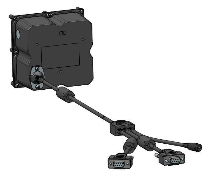
Warnings
This manual contains important information regarding the installation and operation of the LSR118 1D/2D
Barcode Imager and NFC reader. For safe and reliable operation of the imager, installers must ensure that
they are familiar with, and fully understand, all instructions contained herein.
Warranty
Access Ltd warrants that this product shall be free from defects in workmanship and materials for a period of
one year from the date of original purchase. If the product should fail to operate correctly in normal use during
the warranty period, Access will replace or repair it free of charge. No liability can be accepted for damage
due to misuse or circumstances outside Access’ control. Access will not be responsible for any loss, damage
or injury arising directly or indirectly from the use of this product. Access’ total liability under the terms of this
warranty shall in all circumstances be limited to the replacement value of this product.
Radio Frequency Energy
European EMC directive 89/336/EEC
This equipment has been tested and found to comply with the limits for a class A computing
device in accordance with the specifications in the European standard EN 55022. These
limits are designed to provide reasonable protection against harmful interference. This
equipment generates, uses and can radiate radio frequency energy and if not installed and
used in accordance with the instructions may cause harmful interference to radio or
television reception. However, there is no guarantee that harmful interference will not occur in a particular
installation. If this equipment does cause interference to radio or television reception, which can be
determined by turning the equipment on and off, the user is encouraged to correct the interference with one or
more of the following measures: (a) Reorient or relocate the receiving antenna. (b) Increase the separation
between the equipment and the receiver. (c) Connect the equipment to an outlet on a circuit different from that
to which the receiver is connected. (d) Consult the supplier or an experienced radio / TV technician for help.
FCC Compliance Statement (United States)
This equipment generates, uses and can radiate radio frequency energy and if not installed and used
properly, that is, in strict accordance with the manufacturer’s instructions, may cause interference to radio
communication. It has been tested and found to comply with the limits for a class A computing device in
accordance with the specifications in Subpart J of part 15 of FCC rules, which are designed to provide
reasonable protection against such interference when the equipment is operated in a commercial
environment. Operation of this equipment in a residential area may cause interference, in which case the user
at his own expense will be required to take whatever measures may be necessary to correct the interference.
Changes or modifications not expressly approved by the manufacturer could void the user’s authority to
operate the equipment.
Canadian Department of Communications RFI statement
This equipment does not exceed the class A limits for radio noise emissions from digital apparatus set out in
the radio interference regulations of the Canadian Department of Communications.
Le présent appareil numérique n’émet pas de bruits radioélectriques dépassant les limites applicables aux
appareils numériques de la classe A prescrites dans le règlement sur le brouillage radioélectriques publié par
le ministère des Communications du Canada.

Page 2 of 77                                                                       Copyright © Access-IS 2020

Contents
1.   Overview ............................................................................................................................. 6
2.   Specifications ..................................................................................................................... 7
     2.1       Part numbers............................................................................................................. 8
3.   Installation .......................................................................................................................... 9
     3.1       Unpack the LSR118 .................................................................................................. 9
     3.2       Connection ................................................................................................................ 9
     3.3       Mounting ................................................................................................................. 10
     3.4       Barcode interface options ........................................................................................ 10
     3.5       NFC interface options .............................................................................................. 11
     3.6       Barcode module installation (serial device).............................................................. 12
     3.7       Barcode module installation (USB device) ............................................................... 12
     3.8       NFC module installation (serial device) ................................................................... 12
     3.9       NFC module installation (USB device) .................................................................... 13
     3.10 Test the device ........................................................................................................ 13
     3.11 Barcode configuration software ............................................................................... 13
     3.12 Communicate with the NFC module ........................................................................ 13
     3.13 Troubleshooting....................................................................................................... 14
     3.14 Maintenance............................................................................................................ 14
4.   Barcode operating modes ............................................................................................... 15
     4.1       Mode summary ....................................................................................................... 15
     4.2       Dumb mode............................................................................................................. 16
     4.3       Host mode ............................................................................................................... 17
     4.4       Interactive mode ...................................................................................................... 19
5.   Barcode command reference .......................................................................................... 21
     5.1       Basic configuration .................................................................................................. 22
     5.2       Prefix and suffix solutions ........................................................................................ 23
     5.3       LSR118 illumination ................................................................................................ 24
     5.4       Indicator control ....................................................................................................... 26
     5.5       Development commands ......................................................................................... 27
     5.6       Triggering ................................................................................................................ 29
     5.7       Counter ................................................................................................................... 30
6.   NFC operation................................................................................................................... 31
     6.1       Summary of operation ............................................................................................. 31
     6.2       Serial communication .............................................................................................. 33
     6.3       Notifications and data exchanges (serial connection) .............................................. 34
     6.4       MIFARE cards ......................................................................................................... 37
     6.5       Contactless microprocessor smartcards .................................................................. 38

Page 3 of 77                                                                                          Copyright © Access-IS 2020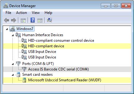
7.   MIFARE media commands and responses ..................................................................... 39
     7.1      MIFARE get media type .......................................................................................... 39
     7.2      MIFARE load key .................................................................................................... 40
     7.3      MIFARE authenticate block (key A or key B) ........................................................... 41
     7.4      MIFARE read block (key A or key B) ....................................................................... 42
     7.5      MIFARE write block (key A or key B) ....................................................................... 43
     7.6      MIFARE create value block (key A or key B) ........................................................... 45
     7.7      MIFARE increment value block (key A or key B) ..................................................... 46
     7.8      MIFARE decrement value block (key A or key B) .................................................... 47
     7.9      MIFARE Ultralight read block .................................................................................. 49
     7.10 MIFARE Ultralight write block .................................................................................. 50
     7.11 MIFARE Ultralight-C authenticate - part 1................................................................ 51
     7.12 MIFARE Ultralight-C authenticate - part 2................................................................ 52
     7.13 MIFARE transceive direct ........................................................................................ 54
     7.14 MIFARE failure status codes ................................................................................... 55
8.   NFC management interface commands.......................................................................... 56
     8.1      Get firmware version ............................................................................................... 56
     8.2      Get bootloader version ............................................................................................ 57
     8.3      Switch to bootloader ................................................................................................ 58
     8.4      Get serial number .................................................................................................... 58
     8.5      Set NFC timings ...................................................................................................... 59
     8.6      Get NFC timings ...................................................................................................... 60
     8.7      Enter sleep mode .................................................................................................... 61
     8.8      Exit sleep mode ....................................................................................................... 62
     8.9      Get NFC kernel version ........................................................................................... 63
     8.10 Get media serial number ......................................................................................... 63
     8.11 Disable media arrival and removal notifications ....................................................... 65
     8.12 Set serial interface baud rate ................................................................................... 65
A.   NFC module serial number matching ............................................................................. 67
B.   HID reports – barcode only .............................................................................................. 68
     B.1      Receive data ........................................................................................................... 68
     B.2      Send commands ..................................................................................................... 69
     B.3      Trigger controls ....................................................................................................... 70
C.   NFC module example code and API functions ............................................................... 71
     C.1      Initialise smartcard sub-system ............................................................................... 71
     C.2      Poll for card arrival .................................................................................................. 71
     C.3      Connect to the card ................................................................................................. 71
     C.4      Get ATR of the card ................................................................................................ 72
     C.5      Communicate with card ........................................................................................... 72
     C.6      Determine if ATR indicates MIFARE type ................................................................ 72

Page 4 of 77                                                                                      Copyright © Access-IS 2020
C.7 Disconnect the card................................................................................................. 72 D. ASCII character reference ................................................................................................ 73 E. Document history ............................................................................................................. 77 Page 5 of 77 Copyright © Access-IS 2020
1. Overview
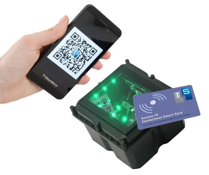
The Access-IS LSR118 is a compact 1D/2D barcode imager with near field communication (NFC)
contactless capabilities.
The device is purpose-designed for use in kiosk and gate applications and its rugged, water-
resistant construction, with no moving parts, enables it to withstand years of indoor and outdoor
public access use.
The device reads all popular linear, PDF417 and 2D barcode symbologies, including QR and Aztec
codes, from smartphones, tablets and printed-paper documents.
The LSR118’s advanced recognition barcode imager is omnidirectional and has near-zero latency. It
captures barcodes within a fraction of a second of presentation in any orientation.
The LSR118 also supports mobile ticketing and mobile wallet payment systems for NFC-enabled
smartphones and tablets, as well as reading contactless smart, credit and debit cards.
• Omnidirectional reading – present the barcode at any angle.
• Reads barcodes and NFC cards, labels and devices from a single point of presentation.
• Red and green indicators to
show good and bad reads.
• Robust unit with a small
footprint; easily integrated
into kiosks and gates.
• Fully sealed, water-resistant
housing suitable for
integration in indoor or
outdoor kiosks, gates and
turnstiles.
• Quick plug-in design reduces
cost of kiosk integration.
• RS232 and USB (serial or
keyboard) interface options.
• Fully configurable output data
formats.
• Interactive mode allows host
application to control barcode
reader functions.
Figure 1. LSR118 1D/2D Barcode Imager and NFC reader
Page 6 of 77 Copyright © Access-IS 20202. Specifications
Specification Details
Dimensions (L x H x W) 109.8 mm x 67.4 mm x 105.9 mm
Weight 592 g (with cable)
Environmental Operating temperature: -25ºC to 50ºC
Storage temperature: -30ºC to 70ºC
Humidity: 95% RH, non-condensing
IP67
Body Black ABS
Glass 4 mm Toughened White Soda Lime; BS EN60068-2-75 & IEC
62262:2002, rated to 3.5 J impact
Power requirements 5 V DC
Requires USB power injector cable or independent power supply
Electrical interface Serial (RS232C) and 5 V USB
Barcode reading Reads barcodes from mobile phones, tablets and paper
Linear: Code 2 of 5, Interleaved 2 of 5, EAN13, Code 3 of 9,
Code 128 (plus others)
2D: PDF417, QR, Aztec, DataMatrix, (plus others)
NFC EMV: Certified to Level 1
Supported media: ISO14443 type A and B cards (Java cards);
max baud 424K (extendable to 848K)
MIFARE UL, Classic 1K, Classic 4K, UL-C, MIFARE Plus; max
baud 106K
MTBF 85,000 hours
Approvals CE EMC Class B
• EN 55022
• EN 55024
CE Low Voltage Directive
• EN 60950-1
• IEC 62471: 2006 - Exempt Class
CE R&TTE Directive
• ETSI EN 301 489
• ETSI EN 302 291
FCC 47CFR Part 15 Subpart B Class A
FCC 47CFR Part 15 Subpart C
IEC 60825-1 LED Safety Class 1
Page 7 of 77 Copyright © Access-IS 20202.1 Part numbers Product Part Number Serial connected LSR118 AKEGEOSA941 USB power injector cable 5KBD133402 USB connected LSR118 AKEGEOSA902 Serial cable 5KBD387302 USB cable 5KBD386301 An external power supply is available, if required. Please contact the Access-IS sales team: sales@access-is.com. Page 8 of 77 Copyright © Access-IS 2020
3. Installation
3.1 Unpack the LSR118
Unpack the LSR118 and ensure that you have the following items:
•   Advisory notice card.
•   LSR118 device with attached serial cables or USB cable.
•   USB power injector cable or power supply (IEC cable not supplied).
Report any missing items or damage immediately to your Sales Representative.

3.2 Connection
Connect the LSR118 directly to two RS232 ports or a USB port depending on the product version.

Note: The cable is sealed into the unit to prevent entry of water, moisture and dust. Cable length is
2 m for serial and USB versions.

3.2.1 Connection to RS232

                   Serial and power cables connected to LSR118 device

                                              USB power injector cable to a powered USB port
                                              on host PC (or connection to an external power
                                              supply)
                To COM ports on the host PC
                                    Figure 2. Connection to RS232

3.2.2 Connection to a USB port

                    USB and power cables connected to LSR118 device

                                              USB power injector cable to a powered USB port
                                              on host PC (or connection to an external power
          To a USB port on the host PC        supply)

                                     Figure 3. Connection to USB

Page 9 of 77                                                            Copyright © Access-IS 2020
3.3 Mounting
Mount the LSR118 into a kiosk, gate or similar device, if required. Refer to Figure 4 for the
LSR118’s dimensions (in millimetres) and mounting points.
For optimum performance, do not position the LSR118 in direct sunlight.
NFC INSTALLATION WARNING
To optimise the performance, DO NOT install the LSR118 so that its NFC antenna is within 40 mm
of a large metal or electrically conductive component or structure.
Failure to observe this instruction may lead to the product’s NFC performance deteriorating or even
failing completely.
Figure 4. LSR118 dimensions and mounting points
Use three M3 screws (not provided) to mount the unit. Maximum insertion depth is 6 mm; minimum
recommended insertion depth is 2 mm.
3.4 Barcode interface options
3.4.1 Serial connection
Connect a serial LSR118 device using an RS232 interface directly into a COM port. You must
specify the baud rate, parity, data bits and stop bits.
Note: A serial LSR118 communicates directly with the COM port and does not require any
additional drivers to be loaded.
3.4.2 USB connection
Connect a USB LSR118 device using one of three possible options. These options are compatible
with all Linux and Windows operating systems from XP onwards.
Page 10 of 77 Copyright © Access-IS 20203.4.2.1 Keyboard interface Virtual keyboard using Windows or Linux drivers This option allows the device to operate without additional drivers, with the LSR118 emulating a keyboard. This is one-way communication; it is not possible to control the device directly in this mode. This mode will be slower than the other options as it adds an inter-character delay when typing the barcode data. 3.4.2.2 CDC interface Virtual serial mode using the Windows CDC driver This option assigns a COM port and the device communicates as a virtual serial device. Due to the nature of CDC serial port drivers, the COM port disappears if the unit is unplugged. 3.4.2.3 HID interface Access-IS recommend the use of the HID interface for reliability. A HID interface recovers properly in the event of accidental disconnects or system power fluctuations; a CDC interface may not recover in these situations. HID interface using the Access driver (Windows only) The Access Serial Ports Service driver is fully configurable and outputs data in virtual serial or virtual keyboard. The output can be parsed and reformatted. The serial port is permanent and does not disappear if you unplug or hot swap the unit. This is one-way communication and the only command that you can send to the device is AIS_BO to enable or disable barcode reading. Refer to page 27 for more information. HID interface without the Access driver This method is only suitable is you are familiar with HID programming. It is possible to communicate directly with the LSR118 using the operating system’s built-in HID drivers. In this instance, HID reports, exactly 64 bytes in length, are sent between the host and the LSR118. The implementation of this driver and the method of interaction will depend on the version of the host operating system. You should refer to the HID programming guide for the operating system you are using. Refer to HID reports – barcode only on page 67 for the details of the HID reports used with the LSR118. 3.5 NFC interface options 3.5.1 Serial connection Connect the NFC module using an RS232 interface directly into a COM port. Note: A serial LSR118 communicates directly with the COM port and does not require any additional drivers to be loaded. 3.5.2 USB connection The NFC module enumerates as a standard chip card interface device (CCID) smartcard reader. When you connect the device to the host, the NFC module uses the default Windows CCID drivers. It is not necessary to install custom drivers when running Windows XP and above. Page 11 of 77 Copyright © Access-IS 2020
3.6 Barcode module installation (serial device)
A serial LSR118 communicates directly with the COM port and does not require any additional
drivers to be loaded. Serial connectors are labelled: CONN1 = Barcode , CONN2 = NFC module.
1. Switch off the computer.
2. Connect the serial cables to COM ports on the computer and finger-tighten the two thumbscrews
   to secure the connectors to the port.
3. If using a USB power injector cable, plug the injector cable into the coaxial power connector on
   the splitter cable and then plug the USB connector into a powered USB port on the computer.
   If using an Access-supplied power supply, plug the power cable into the coaxial power
   connector on the splitter cable and then connect the external power supply to an AC outlet.
4. Once the device is connected, switch on the computer.

3.7 Barcode module installation (USB device)
Note: If you intend to use the Access driver, ensure that you install the driver before you connect
the LSR118 to the computer.

3.7.1 Driverless keyboard output
There is no additional driver required for this mode. Connect the USB cable from the LSR118 to a
USB port on the computer.

3.7.2 CDC Windows driver
This method of USB installation uses the Windows CDC drivers.
For this method to operate, you must install the CDC drivers using the file, AccessISUSBCDC.inf,
which you can download from http://www.access-is.com/gettingstarted/.
The download (USB Driver for CDC Mode) includes full instructions for use.
Windows assigns a virtual COM port to the LSR118 device. You can find out the COM port number
in Device Manager. You will require the port number to configure the LSR118.

3.7.3 Custom HID

3.7.3.1 HID interface using the Access serial driver (Windows only)
The recommended method for using a USB LSR118 is to configure the device to operate in HID
mode. This allows the device to communicate with the Access driver.
For this method to operate, you must install first the Access driver (Access Serial Ports Service
(ASPS)). Download ASPS from http://www.access-is.com/gettingstarted/.
The download (ASPS Software) includes full instructions for use.
Ensure that you install the driver before connecting the LSR118 to the host.

3.7.3.2 HID interface without the Access driver
There is no additional driver required for this mode. Connect the USB cable from the LSR118 to a
USB port on the computer.

3.8 NFC module installation (serial device)
A serial LSR118 communicates directly with the COM port and does not require any additional
drivers to be loaded. Serial connectors are labelled: CONN1 = Barcode , CONN2 = NFC module.
Refer to Barcode module installation (serial device) on page 12 for installation instructions.

Page 12 of 77                                                          Copyright © Access-IS 2020
3.9 NFC module installation (USB device)
When you connect a USB-connected LSR118 device to the host, Windows automatically detects the
hardware and installs the standard CCID smartcard reader drivers. Some versions of Windows may
prompt you to search automatically for a driver. The NFC module also exposes a HID interface for
configuration and control. Refer to NFC management interface commands on page 56 for the
command set and its responses.
In Device Manager, the smartcard reader and HID-compliant device represent the NFC module. The
barcode device appears under Ports (COM & LPT).

       Figure 5. NFC module and barcode device in Device Manager (other device types not shown)

3.10 Test the device
Once you have connected the device and installed the relevant drivers, if applicable, you can test
the device. To do this, wave a piece of paper in front of the glass; the reader’s LEDs should
illuminate. If the device fails to respond when connected to the host, refer to the Troubleshooting
section in this document.

3.11 Barcode configuration software
Connect to, and configure, the LSR118 using your own configuration tool, a terminal emulation
program or the Access-IS configuration tool, which you can download from http://www.access-
is.com/gettingstarted/.
Refer to the Barcode command reference on page 21 for details of the barcode commands, which
you can use to configure the LSR118.

3.12 Communicate with the NFC module
Once the NFC module is enumerated, it registers itself with the Windows Smartcard Resource
Manager. Since the NFC module is Personal Computer/Smart Card (PC/SC) compatible, you can
use standard Windows smartcard functions to communicate with the module through the Windows
Smartcard Resource Manager API. Refer to the Microsoft website for more detailed information on
the Smartcard Resource Manager API.
For more information on the operation of the LSR118’s NFC reader, see page 31. Refer to page 39
for MIFARE media commands and responses and page 56 for NFC management interface
commands.

Page 13 of 77                                                          Copyright © Access-IS 2020
3.13 Troubleshooting
If the LSR118 does not appear to be working, refer to Table 1 to help identify and resolve the
problem. For further assistance, contact support@access-is.com.
Alternatively, use the Contact Customer Support Team page on the Access-IS website.
Note: Do not attempt to disassemble the LSR118 if it does not operate correctly.
Table 1. Troubleshoot the LSR118
Problem Solution
LSR118 not transmitting data to host Check that all cable connections between the LSR118 and
host are secure.
Ensure that the unit has power.
LSR118 cannot scan barcode Ensure that the unit is configured to read the barcode that
you are scanning.
If scanning a document, ensure that the print quality is good.
If scanning a barcode on a mobile phone, ensure that you
set the screen backlight on the phone to its brightest setting.
3.14 Maintenance
3.14.1 Cleaning
Clean the glass with a lint-free cloth. If the glass is dirty, wipe the glass with a lint-free cloth
moistened with isopropyl alcohol or use an alcohol wipe. Do not use abrasive cleaners.
3.14.2 Storage
Store the unit in its original box, at a temperature of -30°C to 70°C.
Page 14 of 77 Copyright © Access-IS 20204. Barcode operating modes The LSR118 operates in one of three ways, as defined by the AISOMD command. Refer to the Barcode command reference on page 21 for a list of commands that you can send to configure the LSR118. 4.1 Mode summary 4.1.1 Dumb mode The LSR118 is a one-way communication device. The device detects the media and activates the imager and illumination. When the LSR118 reads the barcode, it sends the data to the host, activates the ‘Good Read’ indicators, and disables the imager and illumination. The imager and illumination do not reset until the LSR118 sensor fails to detect any media for 0.5 seconds. 4.1.2 Host mode The LSR118 is a two-way communication device that reads barcodes and waits for a host to accept or reject the barcodes. The device detects the media and activates the imager and illumination. When the device reads the barcode, it sends the data to the host and disables the imager and illumination. The LSR118 waits for a response from the host to accept or reject the data, which activates the ‘Good Read/Bad Read’ indicators on the device. The LSR118 waits for up to two seconds for an ‘Accept/Reject/Ignore’ command to activate indicators. The host sends an ‘Ignore’ command to reset the imager if no response from the indicators is required. The imager and illumination do not reset until the LSR118 sensor fails to detect any media for 0.5 seconds. The ‘Ignore’ command requires version 1.0.21 (or later) of the firmware. 4.1.3 Interactive mode Note: This is not the recommended mode for new installations. The LSR118 is a two-way communication device, controlled fully by a host. The LSR118 detects the media and sends a command to the host with this information. If the media is removed, a second command is sent telling the host that the media is no longer detected. If the media is present, the host sends a command to activate the imager and illumination. When the LSR118 reads the barcode, it sends data to the host. The imager and illumination are not disabled. The LSR118 waits for a response from the host to accept or reject the data, which activates the ‘Good Read/Bad Read’ indicators and disables the imager and illumination. An ‘Ignore’ command may also be used, although untriggering the unit is more useful in most cases. At any time, the host can send ‘Good Read’ or Bad Read’ commands activate or deactivate the imager and illumination. Page 15 of 77 Copyright © Access-IS 2020
4.2 Dumb mode
Figure 6 shows the process for a LSR118 in Dumb mode.

                                  Reader Idle

                                Media Detected

                                   Imager and
                                   Illumination
                                     Activated

                                                          Lights ‘Good
                                 Barcode Read           Read’ (as Settings
                                                            Instruct)

                                Data Sent to Host

                                  Imager and
                                  Illumination
                                  Deactivated

                                  Reader Idle

                                   Figure 6. Dumb mode process flow

4.2.1 Dumb mode example
Comments                    LSR Command to Host                                 Host Command to LSR
Media placed in front of    -                                                   -
LSR118.
Imager activated and        Data sent as configured (USB/Serial)                -
barcode scanned.
Illumination activated as
defined in the settings.
No media detected for 0.5   -                                                   -
seconds; LSR118 resets.

Page 16 of 77                                                                Copyright © Access-IS 2020
4.3 Host mode
Figure 7 shows the process for an LSR118 in Host mode.
Reader Idle
Media Detected
Imager and
Illumination
Activated
Barcode Read
Data Sent to Host.
Imager and
Illumination
Deactivated
Reject Accept or Reject? Accept
Ignore Command or
No Response within Timeout
Lights ‘Bad Read’ Lights ‘Good
(as Settings Reader Idle Read’ (as Settings
Instruct) Instruct)
Figure 7. Host mode process flow
Page 17 of 77 Copyright © Access-IS 20204.3.1 Host mode example 4.3.1.1 Accept Comments LSR Command to Host Host Command to LSR Media placed in front of - - LSR118. Imager activated and Data sent as configured (USB/Serial) - barcode scanned. Illumination activated as defined in the settings. Host decides to accept or - ‘Good Read’: reject the data. AISXXR0 Lights activated as defined - - in the ‘Good Read’ settings. No media detected for 0.5 - - seconds; LSR118 resets. 4.3.1.2 Reject Comments LSR Command to Host Host Command to LSR Media placed in front of - - LSR118. Imager activated and Data sent as configured (USB/Serial) - barcode scanned. Illumination activated as defined in the settings. Host decides to accept or - ‘Bad Read’: reject the data. AISXXR1 Lights activated as defined - - in the ‘Bad Read’ settings. No media detected for 0.5 - - seconds; LSR118 resets. 4.3.1.3 Ignore Comments LSR Command to Host Host Command to LSR Media placed in front of - - LTR118. Imager activated and Data sent as configured (USB/Serial) - barcode scanned. Illumination activated as defined in the settings. Host decides to accept or - ‘Ignore and Continue’: reject the data. AISXXR2 No media detected for 0.5 - - seconds; LTR118 resets. Page 18 of 77 Copyright © Access-IS 2020
4.4 Interactive mode
Figure 8 shows the process for an LSR118 in Interactive mode. The host can send ‘Good Read’ and
‘Bad Read’ commands to the LSR118 at any time.

                                                   Reader Idle

                                                 Media Detected,
                                                  Message Sent
                                                                      Untrigger
                                                   Requesting
                                                     Trigger

                                                  Send Trigger?

                                                      Trigger

                                                    Imager and
                                                    Illumination                    Force Trigger
                                                      Activated

                                                  Barcode Read

                                                 Data Sent to Host

                 Lights ‘Bad Read’                                                  Lights ‘Good
                                                    Accept or
                    (as Settings        Reject                       Accept       Read’ (as Settings
                                                     Reject?
                      Instruct)                                                       Instruct)

                                                 Ignore Command

                                                   Imager and
                                                   Illumination                    Force Untrigger
                                                   Deactivated

                                                   Reader Idle

                                     Figure 8. Interactive mode process flow

Page 19 of 77                                                                       Copyright © Access-IS 2020
4.4.1 Interactive mode example 4.4.1.1 ‘Good Read’ initiated by LSR detecting media Comments LSR Command to Host Host Command to LSR Media placed in front of [0x16][0x0D]TRIG:1[0x16][0x0A] - LSR118. LSR118 sends commands to host notifying of media. Host sends a command to - [0x16][0x74][0x0D] trigger the imager. Imager activated and Data sent as configured (USB/Serial) - barcode scanned. Illumination activated as defined in the settings. Host decides to accept or - ‘Good Read’: reject the data. AISXXR0 Lights activated as defined - - in the ‘Good Read’ settings. No media detected for 0.5 - - seconds; LSR118 resets. 4.4.1.2 ‘Good Read’ initiated by host sending trigger command Comments LSR Command to Host Host Command to LSR Host sends a command to - [0x16][0x74][0x0D] trigger the imager. This could be due to a second sensor. Imager activated, it remains - - activated until untriggered or a ‘Good Read/Bad Read’ command is received. Lights activated as defined in the settings. Data read by imager. Data sent as configured (USB/Serial) - Host decides to accept or - ‘Good Read’: reject the data. AISXXR0 Lights activated as defined - - in the ‘Good Read’ settings. No media detected for 0.5 - - seconds; LSR118 resets. Page 20 of 77 Copyright © Access-IS 2020
5. Barcode command reference
Commands are sent with a prefix of [0x16][0x4D][0x0D] causing the command sequence to
take the form [0x16][0x4D][0x0D]. The menu commands are six characters
long with a parameter (if required).
To send a command to modify a configuration parameter
Send the six character command concluded by a dot ‘.’ or an exclamation mark ‘!’. The dot stores
the setting permanently and the exclamation mark keeps it temporarily until power is removed from
the device.
For example, [0x16][0x4D][0x0D]AISKBL1.sets the keyboard localisation to United States
when the device is operating as a USB keyboard.
To query the current settings (including a temporary one)
Send the six character command with a ‘?’ instead of the parameter and the LSR118 will return the
command with the current setting. Note the ‘?’ must be followed with ‘.’
For example, [0x16][0x4D][0x0D] AISINF?. queries the device interface and returns the
current value.
To query the stored value
Send the six character command with a ’^’ instead of the parameter and the LSR118 will return the
command with the stored setting. Note the ‘^’ must be followed with ‘.’
For example, [0x16][0x4D][0x0D] AISINF^. returns the current illumination mode.
To list parameter options
Send the six character command with a ‘*’ instead of the parameter and the LSR118 will return the
command with the parameter options. Note the ‘*’ must be followed with ‘.’

Page 21 of 77                                                        Copyright © Access-IS 2020
5.1 Basic configuration
These commands set the device interface, connection parameters and specify the operating mode.
Table 2. Basic configuration commands

Command            Description                               Default     Parameters/Range
AISINF             Selects the device interface.             0           0 - Serial
                   When a Serial cable is used, the                      1 - USB serial (CDC)
                   configuration is overruled and AISINF0                2 - USB keyboard
                   is used.                                              3 - HID POS
                   When a USB cable is used, the
                   configuration AISINF0 is overruled and
                   AISINF1 is used.
AISBAU             Sets the baud rate for a Serial           9           0 - 300 bps
                   connection.                                           1 - 600 bps
                   Only used when AISINF is set to 0                     2 - 1200 bps
                   (Serial).                                             3 - 2400 bps
                                                                         4 - 4800 bps
                                                                         5 - 9600 bps
                                                                         6 - 19200 bps
                                                                         7 - 38400 bps
                                                                         8 - 57600 bps
                                                                         9 - 115200 bps
AISSCP             Sets the connection parameters for a      2           0 - 7N1
                   Serial connection.                                    1 - 7N2
                   Only used when AISINF is set to 0                     2 - 8N1
                   (Serial).                                             3 - 7E1
                                                                         4 - 7E2
                                                                         5 - 8E1
                                                                         6 - 7O1
                                                                         7 - 7O2
                                                                         8 - 8O1
AISKBL             Keyboard localization; this defines the   0           0 - US   (United States)
                   Windows keyboard mapping for correct                  1 - UK   (United Kingdom)
                   output of characters.                                 2 - IT   (Italy)
                   Only used when AISINF is set to 2 (USB                3 - ES   (Spain)
                   keyboard).                                            4 - DE   (Germany)
                                                                         5 - CH   (Switzerland)
                                                                         6 - CZ   (Czech Republic)
                                                                         7 - FR   (France)
                                                                         8 - BE   (Belgium)
                                                                         9 - SE   (Sweden)
AISCHR             Sets the inter-character delay (in        2           0–250 milliseconds
                   milliseconds).
                   Only used when AISINF is set to 2 (USB
                   keyboard).
AISOMD             Indicator mode setting.                   0           0 - Dumb mode
                                                                         1 - Host mode
                                                                         2 - Interactive mode
AISTAM             Triggers Auto mode.                       0           0 - Normal operation
                   Only used when AISOMD is set to 2                     1 - Automatic untrigger
                   (Interactive).                                        when media removed

Page 22 of 77                                                          Copyright © Access-IS 2020
Command Description Default Parameters/Range
DLYGRD Sets the delay between successful 2000 0–25000
reading of one barcode and the reading
of another barcode.
Each unit is equivalent to 1 millisecond.
5.2 Prefix and suffix solutions
These commands allow you to add a prefix and/or suffix to all barcodes.
Note: If you send more than one prefix or suffix to the device, they will stack in chronological order.
You must send a clear command if you want to use a single prefix or suffix.
Table 3. Prefix and suffix commands
Command Description Default Parameters/Range
PREBK299xx Adds a prefix to all barcode symbologies. - xx - Hex value
Any two-character hex ASCII code can
replace xx.
For example, to add STX (Start of Text)
as a prefix, use the command
PREBK29902.
You can add more than one prefix, as
required.
PRECA2 Clears all prefixes. - -
SUFBK299xx Adds a suffix to all barcode symbologies. - xx - Hex value
Any two-character hex ASCII code can
replace xx.
You can add more than one suffix, as
required.
For example, to add CR (Carriage
Return) and ETX (End of Text) as a
suffix, use the command
SUFBK2990D03.
SUFCA2 Clears all suffixes. - -
Page 23 of 77 Copyright © Access-IS 20205.3 LSR118 illumination
The standard method of reading barcodes cycles the illumination on and off. You can control
illumination for various different applications using the commands in Table 4. For example, it is often
beneficial to turn off the illumination to prevent reflections from shiny surfaces, for example, mobile
phones.
Table 4. Illumination commands
Command Description Default Parameters/Range
AISILL Adaptive illumination mode (see page 2 0 - Off (Phone only)
25). 1 - Off (Paper only)
2 - On (Paper optimised)
3 - On (Phone optimised)
AISONT Illumination on time. 8 0–200
Applies to AISILL modes 2 and 3 only
(adaptive illumination on).
Each unit is equivalent to 100
milliseconds.
AISOFT Illumination off time. 8 0–200
Applies to AISILL modes 2 and 3 only
(adaptive illumination on).
Each unit is equivalent to 100
milliseconds.
AISONM Illumination on mode. 0 0 - Normal adaptive
When set to 0, the timing for the operation; uses AISONT
illumination on period is set to a single timing
value, AISONT. 1 - Cycles through AISON1
When set to 1, the illumination on period to AISON3 timings
cycles continuously (while triggered)
through the three AISONx values.
AISON1 Illumination on time 1. 1 0–200
Applies to AISILL modes 2 and 3 only
(adaptive illumination on).
Each unit is equivalent to 100
milliseconds.
AISON2 Illumination on time 2. 2 0–200
Applies to AISILL modes 2 and 3 only
(adaptive illumination on).
Each unit is equivalent to 100
milliseconds.
AISON3 Illumination on time 3. 5 0–200
Applies to AISILL modes 2 and 3 only
(adaptive illumination on).
Each unit is equivalent to 100
milliseconds.
AISOFM Illumination off mode. 0 0 - Normal adaptive
When set to 0, the timing for the operation; uses AISOFT
illumination off period is set to a single timing
value, AISOFT. 1 - Cycles through AISOF1
When set to 1, the illumination off period to AISOF3 timings
cycles continuously (while triggered)
through the three AISOFx values.
Page 24 of 77 Copyright © Access-IS 2020Command Description Default Parameters/Range
AISOF1 Illumination off time 1. 1 0–200
Applies to AISILL modes 2 and 3 only
(adaptive illumination on).
Each unit is equivalent to 100
milliseconds.
AISOF2 Illumination off time 2. 2 0–200
Applies to AISILL modes 2 and 3 only
(adaptive illumination on).
Each unit is equivalent to 100
milliseconds.
AISOF3 Illumination off time 3. 5 0–200
Applies to AISILL modes 2 and 3 only
(adaptive illumination on).
Each unit is equivalent to 100
milliseconds.
5.3.1 Adaptive illumination modes
The illumination modes allow you to configure the device to provide the best lighting to read
barcodes on different types of media.
5.3.1.1 0 - Off (Phone only)
Adaptive illumination is off. The illumination LEDs do not light when you present media to the
device.
5.3.1.2 1 - Off (Paper only)
Adaptive illumination is off. The illumination LEDs light when you present media to the device. The
LEDs illuminate until the device reads the barcode or you remove the media.
5.3.1.3 2 - On (Paper optimised)
Adaptive illumination is on. The illumination LEDs switch ‘On’ and ‘Off’ continuously when you
present media to the device. The LEDs cycle ‘On’ and ‘Off’ until the device reads the barcode or you
remove the media. Use the illumination commands in Table 4 to set the ‘On’ and ‘Off’ time.
5.3.1.4 3 - On (Phone optimised)
Adaptive illumination is on. The illumination LEDs switch ‘Off’ and ‘On’ continuously when you
present media to the device. The LEDs cycle ‘Off’ and ‘On’ until the device reads the barcode or you
remove the media. Use the illumination commands in Table 4 to set the ‘Off’ and ‘On’ time.
Page 25 of 77 Copyright © Access-IS 20205.4 Indicator control
These commands control the behaviour of the ‘Good Read’ and ‘Bad Read’ LEDs.
Note: There are no lid lights on the LSR118; these are replaced by the NFC antenna.
Table 5. Indicator LED commands
Command Description Default Parameters/Range
AISGDT ‘Good Read’ LED indicator duration. 5 0–200
Each unit is equivalent to 100
milliseconds.
AISGDS ‘Good Read’ duration start. 0 0 - At ‘Good Read’
Specifies when the ‘Good Read’ indicator 1 - At media removal
illuminates.
AISGIN ‘Good Read’ indication stop. 1 0 - At media removal
Specifies when the ‘Good Read’ indicator 1 - Continues after media
extinguishes. removal
AISBDT ‘Bad Read’ LED indicator duration. 8 0–200
Each unit is equivalent to 100
milliseconds.
AISBDS ‘Bad Read’ duration start. 0 0 - At ‘Bad Read’
Specifies when the ‘Bad Read’ indicator 1 - At media removal
illuminates.
AISBIN ‘Bad Read’ indication stop. 1 0 - At media removal
Specifies when the ‘Bad Read’ indicator 1 - Continues after media
extinguishes. removal
AISGSL Switches between LED locations for the 5 0 - No lights
‘Good Read’ indicator. 1 - Board green lights
2 - Board red lights
AISBSL Switches between LED locations for the 10 0 - No lights
‘Bad Read’ indicator. 1 - Board green lights
2 - Board red lights
Page 26 of 77 Copyright © Access-IS 20205.5 Development commands
5.5.1 Firmware and imager levels
The firmware levels identify the release and build of a unit. Send the command AISFWV? to obtain
this information. For example: SB 01.00.00 is a first generation LSR118.
To check the latest firmware version or to update firmware, contact support@access-is.com.
Table 6. Firmware and imager commands
Command Description Default Parameters/Range
AISXXR Simulates read outcome. - 0 - Good Read
Used in Interactive mode to 1 - Bad Read
communicate to the user after the host 2 - Ignore (requires version
has checked the data. 1.0.21 of the barcode
Only applicable to Interactive mode and module firmware)
Host mode.
AISIOP Interactive mode option flag. 0 0 - Disabled
Only applicable to Interactive mode 1 - Enabled
(AISOMD2).
If this flag is set, then the TRIG
messages from the LSR118 are sent
only on media detect and media
removed, regardless of commands from
the host.
AISRDS Changes the configuration back to its - 1
default values.
Warning: This command resets all
parameters to their default values,
including any values specific to your
stored configuration.
AISFWV Returns the version of the firmware. - -
AIS_WA Returns the firmware version of the - -
imager.
AIS_TD Returns the timestamp of the firmware 1 -
release.
AIS_BO Enables or disables barcode reading. 1 0 - Off
This command is stored in volatile 1 - On
memory so will return to the default
setting on power cycle.
AISDLE Include DLEs (Data Link Escape). 0 0 - Off
1 - On
AISNRD Sets a ‘No Read’ message, sent at 0 0 - Off
defined intervals. 1–60000 milliseconds
232CRD CTS is raised when a ‘Good Read’ 0 0 - Off
output is received. 1 - On
232CTS Hardware handshaking - requires the 0 0 - Off
CTS to be high. 1 - On
Page 27 of 77 Copyright © Access-IS 20205.5.2 Status LED
The LSR118 contains two small orange LEDs on the main circuit board, typically used for debug
purposes only. We recommend turning these off in normal use.
A typical configuration will have these turned off, but the default values will be as below (for
example, when using the AISRDS command).
Note: You can combine more than one function by adding the function numbers together. For
example, Brownout status and Intelli sensor reset is 48 + 64 = 112.
Table 7. Status LED commands
Command Description Default Parameters/Range
AISLS1 Status LED function. 4 0 - None
1 - Power on
2 - Loader
3 - Power on and loader
4 - Power on except when
triggered
16 - Brownout detection
(Diagnostic)
32 - Brownout reset
(Diagnostic)
48 - Brownout status -
Detection or reset
(Diagnostic)
64 - Intelli sensor reset
(Diagnostic)
128 - Watchdog reset
(Diagnostic)
AISLS2 Status LED function. 2 0 - None
1 - Power on
2 - Loader
3 - Power on and loader
4 - Power on except when
triggered
16 - Brownout detection
(Diagnostic)
32 - Brownout reset
(Diagnostic)
48 - Brownout status -
Detection or reset
(Diagnostic)
64 - Intelli sensor reset
(Diagnostic)
128 - Watchdog reset
(Diagnostic)
Page 28 of 77 Copyright © Access-IS 20205.6 Triggering
These commands control triggering and untriggering of the LSR118.
Table 8. Triggering commands
Command Description Default Parameters/Range
AISTUT Automatically untrigger. 0 0–25000 milliseconds
AISTMD Convert trigger modes. 1 0 - Imager must be
Warning: This is for advanced triggered
users only and modification may 1 - Imager in presentation
cause the device to become inoperable. mode
AISTST Soft trigger timeout. 2000 1000–25000 milliseconds
Specifies how long the LSR118 retains
barcode information before discarding.
Only used with AISOMD1 or AISOMD2.
AISTPT Presentation trigger timeout. 2000 1000–30000 milliseconds
Specifies how long the imager will wait
before reading a new barcode.
SNSSMO Sensor maximum on time. 600 0–60000
Set to 0 to disable this feature.
Each unit is equivalent to 100
milliseconds (600 = 60 seconds).
If the infrared sensor detects media for
more than the timeout (for example,
because there is a sticker on the glass),
it is disabled allowing the imager to work
in presentation mode.
5.6.1 Interactive mode
The commands to trigger the LSR118 for Interactive mode do not follow the same format as
described in Table 8. For Interactive mode, trigger commands are sent as [0x16][0x74][0x0D]
and [0x16][0x75][0x0D] (see Table 9) instead of the [0x16][0x4D][0x0D] command.
Table 9. Triggering commands in Interactive mode
Command Description Default Parameters/Range
[0x16][0x74][0x0D] Triggers the LSR118. - -
[0x16][0x75][0x0D] Untriggers the LSR118. - -
This cannot be done when
media is detected by the
LSR118.
Page 29 of 77 Copyright © Access-IS 20205.7 Counter
These commands display the number of ‘Good’ or ‘Bad’ reads made by the device.
Table 10. Counter commands
Command Description Default Parameters/Range
AISGRC ‘Good Read’ counter. 0 -
Cannot be reset.
AISBRC ‘Bad Read’ counter. 0 -
Cannot be reset.
Page 30 of 77 Copyright © Access-IS 20206. NFC operation
Near Field Communication (NFC) is a standard form of communication between an NFC reader and
NFC supported media like smartcards, tags and smart phones.
NFC is a short-range wireless technology, which allows two devices to exchange securely small
amounts of data over a distance of a few centimetres.
The adoption of NFC technology by mobile devices and passports has seen NFC technology gain in
popularity. Consumers can now perform contactless transactions with a single touch, and use NFC
devices for public transport, ticketing and access control.
The LSR118 operates in NFC reader mode and processes NFC (and barcode) data from a single
point of presentation in any orientation.
The NFC module in the LSR118 is Personal Computer/Smart Card (PC/SC) compatible and you
can use standard Windows smartcard functions to communicate with the module through the
Windows Smartcard Resource Manager API.
6.1 Summary of operation
An NFC reader reads/writes blocks from/to a microprocessor or MIFARE card. When NFC media
connects to the LSR118’s NFC reader, the device retrieves an Answer to Reset (ATR) from the
card.
The ATR specifies certain communication parameters, including the card’s nature and state.
• If the ATR identifies a microprocessor card, the host application sends Application Protocol Data
Unit (APDU) commands to the card using the Windows Smartcard API.
The format of the command and response APDUs depend on the type of media.
• If the media type is a MIFARE card, the NFC module constructs an ATR from the fixed elements
that identify the card. See page 33 for more information.
Once the application detects a MIFARE-type card, it can then use MIFARE commands to
communicate with it (see page 39).
The host sends APDU or MIFARE commands to the card over the PC/SC interface using the
SCardTransmit function in the Windows Smartcard API and gets data back from the card.
Once communication is complete, or a user removes the card, the NFC module disconnects from
the card and waits for another card connection.
Figure 9 shows an overview of the process that the NFC module in the LSR118 uses to identify and
communicate with contactless media.
Page 31 of 77 Copyright © Access-IS 2020Figure 9.NFC module-contactless media process flow Page 32 of 77 Copyright © Access-IS 2020
6.2 Serial communication
6.2.1 Communication parameters
The NFC module in a serial-connected LSR118 uses the following default serial communication
settings. Change the serial device baud rate using the Set serial interface baud rate command (on
page 65).
Table 11. Serial communication default parameters

Parameter                    Value
Baud rate                    115200
Data format                  8 bits
Parity                       None
Stop bits                    1
Flow control                 RTS/CTS

6.2.2 Communicating with individual readers
The individual readers inside the NFC module are identified by unique slot IDs. All CCID packets
should have a CCID header, which has a byte field called bSlot. This field specifies the slot ID of
the reader with which the application wishes to communicate.
The slot ID value uniquely identifies the reader (within NFC module) to which the CCID packet is
sent, and identifies the reader which is sending the response back to the application.
Table 12 shows the Slot ID values and their mapping to the readers.
Table 12. Slot ID and reader mappings

Slot ID value                Reader
0                            NFC
1                            Smartcard #0 (SMC0)
2                            Smartcard #1 (SMC1)
3                            Smartcard #2 (SMC2)
4                            Smartcard #3 (SMC3)
[0xFF]                       Management
The Management Interface is used to set the operating and debug parameters of the NFC module.

Note: Do not send commands to a reader that is not enabled.

6.2.3 Communication format
The data is sent to and from the NFC module in 64-byte chunks. Figure 10 shows how the NFC
module transfers a 256-byte CCID packet.

Page 33 of 77                                                          Copyright © Access-IS 2020
CCID Packet (256 bytes)

           1st 64 byte chunk            2nd 64 byte chunk              3rd 64 byte chunk         4th 64 byte chunk

                                                        At least 2 character                     At least 3 ms idle
                                                        idle time (~200µs)                         time for EOP

                               Figure 10. Example data transfer of a 256-byte data packet
The entire CCID packet including the header is broken down into 64-byte packets, which are
transmitted one at a time. Ensure that there is at least a two-character idle time (approximately 200
microseconds) between consecutive 64-byte chunks. This idle time gives an opportunity for the
serial device to save and clear its receiving buffer. The last data packet can be less than 64 bytes
long. End-of-packet (EOP) is indicated by at least three milliseconds of idle time.
When EOP is received by the module, it internally checks the CCID packet’s length indicated in the
CCID packet header.
•   If the CCID packet header’s length is equal to (or less than) the received CCID packet length,
    then the module processes that packet.
•   If the CCID packet header’s length is more than the received CCID packet size length, then the
    module waits for the next 64-byte chunk to arrive.

Note: When a CCID packet transmission starts, the first 64-byte chunk includes the CCID header,
which indicates the slot ID where the data is being sent to or received from.
Each command message sent to a particular reader receives an appropriate response from the
NFC module. The serial host does not send another command message to a reader until it receives
a response. However, the serial host may send command messages concurrently to different
readers at the same time. The NFC module may not respond in the same sequence as the sent
commands. The response depends on the internal priority of the readers and the time taken to
process the request by the media.

6.3 Notifications and data exchanges (serial connection)
6.3.1 Media arrival and removal notification
The NFC reader sends out three bytes to notify media arrival or removal. The format of these three
bytes is shown in Table 13.
Table 13. Media arrival or removal

1st Byte                        2nd Byte                       3rd Byte
Always [0x50]                   Slot / media status            Media type

Slot / media status
The first most significant 4 bits denote the reader slot ID. The least 4 bits denote the media status. If
media status is 0 then the media is not present. If it is 1, then the media is present.

Page 34 of 77                                                                              Copyright © Access-IS 2020
You can also read