Electric Vehicle Ultra-Fast Battery Chargers: A Boost for Power System Stability? - MDPI
←
→
Page content transcription
If your browser does not render page correctly, please read the page content below
Article
Electric Vehicle Ultra-Fast Battery Chargers: A Boost for Power
System Stability?
Fabio Mandrile * , Davide Cittanti                       , Vincenzo Mallemaci             and Radu Bojoi

                                             Energy Department “Galileo Ferraris”, Politecnico di Torino, 10129 Torino Italy; davide.cittanti@polito.it (D.C.);
                                             vincenzo.mallemaci@polito.it (V.M.); radu.bojoi@polito.it (R.B.)
                                             * Correspondence: fabio.mandrile@polito.it

                                             Abstract: As a consequence of the exponential growth of the electric vehicle (EV) market, DC fast-
                                             charging infrastructure is being rapidly deployed all around the world. Ultra-fast charging (UFC)
                                             stations are starting to pose serious challenges to the electric power system operation, mostly due
                                             to their high peak power demand and unregulated discontinuous operation. To address these
                                             issues, local energy storage can be installed, ensuring a smoother grid power absorption profile and
                                             allowing to provide grid-supporting features. In this work, a control solution for the grid-side AC/DC
                                             converter of next-generation EV UFC stations is proposed. A virtual synchronous compensator (VSC)
                                             control algorithm is implemented, in order to lessen the impact of the charging station on the utility
                                             and to provide the full spectrum of grid ancillary services (i.e., frequency regulation, reactive power
                                             compensation, harmonic reduction, short circuit current generation, etc.). The proposed control
                                             strategy is verified experimentally on a downscaled 15 kVA three-phase inverter, emulating the grid
                                             front-end of the charging station.

                                             Keywords: electric vehicles (EVs); battery chargers; ultra–fast charging (UFC); grid–connected
                                             converters; three-phase inverters; virtual synchronous compensator (VSC); power system stability


Citation: Mandrile, F.; Cittanti, D.;
Mallemaci, V.; Bojoi, R. Electric
Vehicle Ultra-Fast Battery Chargers:
                                             1. Introduction
A Boost for Power System                           Despite the constantly increasing performance and energy density of Li-ion batteries,
Stability? World Electr. Veh. J. 2021, 12,   their cost and weight still poses a major limit to electric vehicle (EV) driving range [1]. The
16. https://doi.org/10.3390/                 limited EV range may be circumvented by having a DC fast charging infrastructure in
wevj12010016                                 place, capable of charging vehicles with a rate similar to refueling an internal combustion
                                             engine (ICE) vehicle. This infrastructure would allow in-city vehicle charging for apartment
Received: 31 December 2020                   dwellers (i.e., without the possibility of home charging) and extend vehicle range during
Accepted: 20 January 2021                    long trips, solving the EV range issue for most of the population. Building such an
Published: 23 January 2021
                                             infrastructure has yet proven to be a major challenge, mainly due to available technology,
                                             competing industry standards and the impact on the grid [2,3]. Nevertheless, according to
Publisher’s Note: MDPI stays neu-
                                             the most recent forecasts, the electric mobility market is starting to rise exponentially [4,5].
tral with regard to jurisdictional clai-
                                             In particular, thousands of fast-charging stations are being installed all around the world at
ms in published maps and institutio-
                                             an incredible pace, as illustrated in Figure 1.
nal affiliations.
                                                   As a result of volume, weight and cost constraints, EV on-board chargers can reach
                                             limited power ratings (i.e., in the order of 3–20 kW) [6–9], which may be considered
                                             acceptable only for overnight charging. For every other use-case, high-power off-board
Copyright: © 2021 by the authors. Li-        DC chargers are required, achieving charging times comparable to refueling a gasoline
censee MDPI, Basel, Switzerland.             car [3,10]. These chargers directly deliver DC current to the vehicle battery pack, meanwhile
This article is an open access article       ensuring galvanic isolation from the mains. As of today, most commercially available DC
distributed under the terms and con-         fast chargers are rated between 50 kW and 150 kW [11], nevertheless a new generation of
ditions of the Creative Commons At-          ultra-fast chargers (UFCs) rated at 350 kW and above are starting to be deployed [12].
tribution (CC BY) license (https://
creativecommons.org/licenses/by/
4.0/).

World Electr. Veh. J. 2021, 12, 16. https://doi.org/10.3390/wevj12010016                                              https://www.mdpi.com/journal/wevj
World Electr. Veh. J. 2021, 12, 16 2 of 21
# (thousands)
Figure 1. Cumulative electric vehicle fast chargers installed worldwide, including AC 43 kW chargers,
DC chargers, Tesla Superchargers and high-power inductive chargers [5].
Conventional DC fast charging stations represent a high-power, unpredictable and
discontinuous load for the electrical system. The large scale diffusion of this kind of
station is increasing the utility daily peak load, directly causing transformer overload and
accelerated aging, meanwhile increasing system power losses [2]. Moreover, their total
lack of flexibility leads to high peak power charges for the station operator, which are then
reflected on the charging cost for the final users, and poses serious challenges to the power
distribution system, affecting its stability and decreasing the power quality [13].
Most of the issues mentioned above can be addressed by having local energy storage
at disposal, either leveraging the EV batteries (i.e., known as vehicle-to-grid operation) or
installing separate storage to the station [14]. A correct sizing of the storage unit provides
great flexibility to the charging station, allowing to reduce its peak power demand and the
size of the protection equipment, thus leading to both lower operational costs and initial
investment [15]. Moreover, the availability of stored energy opens up the possibility of
providing grid ancillary services, such as (1) active power injection/absorption for grid
frequency regulation, (2) reactive power support for voltage regulation, (3) grid harmonic
reduction and (4) fault current generation during voltage dips/swells. These features can
directly support the power distribution system, effectively turning around the drawbacks
of conventional UFC stations, meanwhile allowing for an additional revenue stream for
the station operator [16].
The reason behind the provision of such ancillary services lies in the design and
structure of contemporary electric power systems find their roots in a more than a century
old paradigm [17]. This paradigm relied on the centralized power generation from pro-
grammable sources (e.g., coal power plants), through synchronous generators (SGs), using
the transmission lines and distribution networks to deliver the energy in a unidirectional
way to the AC loads (i.e., motors, lamps, heaters, etc.). Therefore, the operation of such
power systems was designed around the SGs, leading to quality indicators that reflected
their correct behavior. These indicators are [17]:
• a constant frequency (e.g., 50 Hz or 60 Hz);
• a constant voltage amplitude;
• a sinusoidal voltage supply with low harmonic content and limited harmonic
interactions;
• protection of the system in case of faults.
The SGs were, and still are, able to support and preserve these indicators, by providing
the so called ancillary services.
The first grid power quality aspect is the constancy of the frequency. As it is designed,
the power system guarantees the equilibrium between the active power demand and its
consumption by keeping the grid frequency close to its nominal setpoint. Moreover, it is
also important to keep the grid frequency within the given specifications to ensure the
correct rotational speed of electrical machines directly connected to the grid, which are stillWorld Electr. Veh. J. 2021, 12, 16 3 of 21
widespread in industrial applications. This aspect is graphically illustrated by the power
balance of Figure 2. This balance is perturbed in case of generation or load variations,
therefore leading to a frequency drop or rise. With the goal of ensuring the correct operation
of the grid without blackouts, the power system is equipped with frequency relays, which
monitor both the grid frequency and its derivative (or rate of change of frequency, RoCoF),
disconnecting portions of the network in case of faults. In this view, it is important both
to minimize these frequency variations (reduced amplitude) and to reduce the RoCoF, in
order to ensure a correct operation of the protections, with no untimely trips.
50/60 Hz Generation
Load − +
Figure 2. Qualitative representation of the electrical system power balance and its effect on the grid
frequency. The power injected by generators is controlled to keep the frequency at its rated value.
The second cornerstone of power systems is the constancy of the voltage level. The
amplitude of the voltage must be kept within the standard prescriptions and its variation is
strongly related to the reactive power (at least in mainly inductive networks). It is therefore
necessary to manage the reactive power flow towards the grid and this is currently done
by SGs and other static compensators (e.g., capacitor banks or reactors).
Moreover, the electric grid requires a sinusoidal voltage with low distortion in steady-
state conditions. In fact, the presence of harmonic and interharmonic components in the
supply voltage may lead to the following detrimental effects:
• additional high frequency losses in electrical equipment (e.g., transformers, motors . . . );
• worse performance of electric motors and generators directly connected to the grid;
• poorly damped resonances between different components connected to the same grid;
• disturbances in electronic equipment;
• unwanted intervention of protection devices (e.g., breakers).
Therefore, it is important to avoid injecting harmonics into the grid and to compensate
any harmonic content as much as possible. Thanks to their electromechanical construction,
SGs are able to generate a voltage with a very low total harmonic distortion (THD) and
are, therefore, highly suited to this purpose. Moreover, they are able to inject harmonic
current when supplied with distorted voltage, as their stator offers a low impedance path
to frequency components other than the fundamental.
Finally, the structure of the power system must withstand and clear short circuits.
This means that the transmission and distribution networks are protected by breakers (e.g.,
equipped with overcurrent relays) to isolate faulty branches of the network and clear the
fault. Again, SGs are appropriate to trigger such protections. In fact, in case of voltage
reductions at their terminals, as it happens when there is a short circuit in the network, they
automatically inject a fault current. Depending on the electrical distance from the point
of fault (i.e., depth of the voltage reduction at the machine terminals), they inject a larger
or smaller peak current. For near faults, they can easily inject a short circuit current few
times larger than their rated value (e.g., 4–5 pu) without incurring into thermal protections,
thanks to their long thermal time constant. Therefore, they are able to remain connected to
the grid, riding through the fault and supporting the grid itself in abnormal conditions.
Historically, the synchronous alternators of large thermoelectric power plants have
been providing all the mentioned services. Nowadays, due to the decarbonization require-
ments and the rise of power generated by renewable sources, such power plants are beingWorld Electr. Veh. J. 2021, 12, 16 4 of 21
phased out [18]. For this reason, both academic and industrial research have been focusing
on how to provide ancillary grid services by means of static grid–connected converters [19].
In this frame, a particularly promising technology is the virtual synchronous machine
(VSM), which consists of making a power converter behave like synchronous machines,
therefore providing grid ancillary services in the same way [20–23]. The advantage of
this technology is that the inverter can mimic one or more aspects of a real SG, therefore
contributing to the correct operation of the electric grid. Even though this solution has
been mainly proposed for generating units (such as solar fields), it can be also applied to
UFCs in order to make them more grid friendly, by providing ancillary services exploiting
the already available power hardware. The simplest solutions found in the technical lit-
erature [24,25] focus on both active and reactive power exchange to the grid. Therefore,
additional reactive power control loop and voltage regulators are added to the standard
control algorithms of UFCs. These solutions are capable of providing only static ancillary
services, such as primary frequency regulation and voltage regulation, but they are not
able to generate suitable current references to compensate the grid during transients (i.e.,
sudden frequency variations, voltage dips or harmonic distortion). Much better perfor-
mance can be obtained if UFC controllers are equipped with VSM algorithms, which are,
on the contrary, well suited to generate the necessary ancillary services control signals.
Therefore, some researchers have proposed the integration of various VSMs into the
control of both small power chargers and UFCs. Some propose partial ancillary services [26]
(i.e., only frequency support), while others propose full VSM technology, which is able to
provide both active and reactive support [27,28].
While these solutions guarantee satisfactory performance, they fully put the VSM
model in charge of generating the power references of the converter. This means that both
the compensating signals (ancillary services) and the necessary charging power references
must be processed by the VSM model. However, this is not strictly necessary and a plug-in
solution, where the VSM model is only in charge of the ancillary services, while keeping
the standard structure of the UFC control, is preferable. Therefore, in order to fully exploit
the potential of the next-generation EV UFC stations integrating energy storage, this paper
proposes a Virtual Synchronous Compensator (VSC)-based control solution for the grid-
side bidirectional active front-end (AFE) converter. By leveraging the extended knowledge
available on synchronous compensators, grid ancillary services may be provided in a
straightforward and power system friendly manner, turning around the negative impact
of standard unidirectional fast charging stations. Furthermore, since worldwide grid
operators are moving towards the remuneration of some ancillary services [16] provided
by large loads, the proposed solution would represent an additional source of revenue for
the charging station operator.
The proposed compensator solution features the following benefits with respect to the
existing literature:
• the VSC algorithm is a plug-in addon for standard UFCs, enabling them to support
the grid;
• with respect to the early grid supporting UFCs, the VSC-based control is capable of
providing both static (permanent) and dynamic (transient during faults) grid support;
• the already available VSM-based AFEs are either partial (frequency control only) or
put the VSM in charge of the complete management of the UFC, therefore not being
an easy plug-in solution.
This paper is organized as follows. Section 2 describes the evolution of the fast
charging station from the contemporary unidirectional paradigm towards more advanced
bidirectional solutions. In Section 3, the global control scheme of the AFE converter
equipped with the VSC technology is presented, along with some insights regarding
the operation of the adopted VSC (the S-VSC, available in the technical literature). In
Section 4, the proposed control strategy is validated experimentally and the main results
are compared with a more traditional solution. Finally, Section 5 summarizes and concludes
this work.World Electr. Veh. J. 2021, 12, 16 5 of 21
2. Ultra-Fast Charging Stations
State-of-the-art DC fast chargers are normally connected to the low-voltage grid,
leveraging the low-voltage (LV) industrial power electronics expertise and availability.
The structure of an off-board battery charger has no major differences with respect to an
on-board EV charger and normally consists of two power conversion stages [3,6,7,10,11],
schematically illustrated in Figure 3. The first stage is a three-phase grid-connected AC/DC
converter with unity power factor correction (PFC) capabilities, also referred to as active
front-end (AFE). The role of this stage is to absorb the correct amount of power from the
grid while ensuring an input sinusoidal current shaping (i.e., with low distortion and
harmonics) [29]. The second stage is a high-frequency DC/DC converter, which must
provide the output DC current control (i.e., the regulation of the battery charging process)
and galvanic isolation from the grid [30]. In general, both converter stages can be designed
to be either unidirectional or bidirectional.
AC/DC Isolated DC/DC Electric Vehicle (Battery)
Converter Converter
Grid
AC DC
DC DC
Figure 3. Simplified schematic of an off-board DC fast-charger.
A schematical overview of a conventional unidirectional DC fast charging station
is provided in Figure 4. For reasons of simplicity and cost reduction, multiple identical
off-board chargers are connected to the same point of common coupling (PCC). In this
configuration, the power absorbed from the grid is equal to the sum of the charging powers,
preventing any kind of operational flexibility. This results in a high peak power rating
of the grid connection and safety equipment, leading to higher investment costs, and it
impairs the possibility of flattening the load curve by distributing it within the day (i.e.,
when cheaper rates are available), thus also resulting in higher operational costs.
Unidirectional Unidirectional
AFE DC/DC
Grid
AC DC
DC DC
AC DC
DC DC
AC DC
DC DC
Figure 4. Simplified schematic of a conventional unidirectional EV fast-charging station without
energy storage.World Electr. Veh. J. 2021, 12, 16 6 of 21
Having energy storage at disposal, either leveraging the EV batteries or adding
separate storage to the station would allow to tackle the issues mentioned above. While
exchanging power between the vehicle and grid may make sense for low-power chargers
(i.e., with charging sessions of several hours), it is in contrast with the aim of high-power
chargers. Therefore, at least the DC/DC converter stage should be kept unidirectional,
limiting hardware requirements and simplifying communication and interconnection issues
with the vehicles [3,31]. This consideration leads to the UFC station structure illustrated in
Figure 5, where a single bidirectional AFE unit is designed for the whole station, generating
a distributed DC-bus to which the isolated DC/DC stages (i.e., the actual EV chargers in
this case) are connected. The energy storage is also connected to the bus by means of a
DC/DC converter that regulates the power flow provided/absorbed by the storage unit.
This enables the active power decoupling between the vehicle chargers and the grid, thus
allowing for load shifting within the day. Therefore, the correct sizing of the storage unit
allows to drastically reduce the peak power demand of the station and the sizing of the
protection equipment, leading to both lower operational costs and initial investment [15].
Moreover, the bidirectional nature of the AFE, combined with the presence of energy
storage, opens up the possibility of providing grid ancillary services such as frequency
regulation, reactive power support, voltage harmonic reduction and short-circuit current
generation during grid faults.
Bidirectional Unidirectional
AFE DC/DC
Grid
AC DC
DC DC
DC
Local Bidirectional DC
Storage DC/DC
+ − DC
DC DC
DC
Figure 5. Simplified schematic of a next-generation bidirectional EV fast-charging station with
integrated energy storage and distributed DC-bus.
3. Active Front-End Control
Since the proposed control strategy does not depend on the AFE converter topology,
in this paper a simple two-level inverter is considered. As shown in Figure 6, this inverter
is supplied by a DC-bus connected to the energy storage system of the charging station.
On the AC side, the inverter is connected to the LV grid through an LCL filter, which filters
out the switching harmonics [32,33].
The control structure, also reported in Figure 6, consists of two cascaded layers, namely
an outer S-VSC model and an inner current control loop. The measured quantities are the
inverter phase currents iabc , the phase voltages across the filter capacitors vg,abc and the
DC-link voltage vdc . This adds no additional cost compared to traditional AFE converters,
since all these measurements are in any case necessary. Differently from a standard AFE,
however, the proposed solution does not simply feature a vdc controller that provides theWorld Electr. Veh. J. 2021, 12, 16 7 of 21
∗ is obtained by adding up
references for the inner loop. Instead, the current reference idq
two separate contributions, namely the S-VSC power references Pv , Qv and the external
power references P∗ , Q∗ . The external power references P∗ and Q∗ , e.g., coming from the
charging/discharging logic of the local storage or determined by the grid ancillary service
agreements between the grid operator and the station owner, are directly fed to the inverter
current control loop, while the S-VSC adds the extra power reference terms Pv and Qv to
compensate for grid perturbations. In particular, the reactive power Q is responsible for
the voltage regulation at the AC side, while the active power P regulates the grid frequency
and supports the charging process of the EVs and the local storage.
Grid Chargers & Storage
eg AFE
Lg Lf
ia
vdc
ib
vg,a vg,b vg,c ic
Cf
vdc
PWM
P* idq dq iabc vo Zero-Sequence
S-VSC Power to Imax abc Injection
Pv Current
idq ϑr Current vdq dq vabc (Modulation)
vg,abc Qv Eq. (1)
Controller abc
ϑr
ϑr Reference −Imax
Q* Limitation
Figure 6. General schematic overview of the proposed ultra-fast charging (UFC) station active
front-end (AFE) control strategy.
The most significant advantage of the proposed solution is the possibility to directly
turn on and off the power reference signals coming from the S-VSC. Compared to other
solutions, where the VSM model fully controls the power exchange with the grid, this
control strategy allows to disable one or both power channels when they are not needed
or when they are not part of the charging station operating plan. For instance, if the
local storage must be recharged, the AFE contribution to transient frequency support
might be limited or even excluded. The proposed VSC solution, therefore, fully acts as a
plug-in control, able to enhance the grid-side performance of UFC stations with limited
modifications of the standard control algorithms. In this paper, the inverter current control
loops are implemented in a rotating (d, q) frame, which is aligned to the S-VSC rotor frame.
The controlled currents are the inverter-side currents iabc , referred to the (d, q) frame as
id , iq . The grid phase voltages vg,abc are also referred to the (d, q) frame as vg,d , vg,q . The
current reference vector idq ∗ is calculated from the total power references P = P∗ + P ,
v
∗
Q = Q + Qv and the measured grid voltages vg,d , vg,q , as:
∗ 2 P − jQ
idq = id∗ + jiq∗ = . (1)
3 vg,d − jvg,q
The amplitude of the reference current vector is limited to comply with the inverter
rating even during faults, without modifying its position in the (d, q) plane. Therefore, the
ratio between the active and reactive component of the current is not altered. The current
control (current controller block in Figure 6) can be performed using any of the existing
strategies [34]. In this case, a PI + RES (tuned to the 6th harmonic) controller in the (d, q)
rotating frame has been implemented. The tuning of the controller is performed according
to previous literature, to obtain the optimal performance in both steady-state and transient
operations [35].World Electr. Veh. J. 2021, 12, 16 8 of 21
3.1. S-VSC Model
To describe the S-VSC structure, it is practical to introduce a simplified diagram of the
converter and control assembly. This diagram assumes that the inverter behaves as an ideal
current source, injecting exactly its reference values into the grid. The system is therefore
represented in Figure 7. The hardware part is modeled by a controlled current source i∗
connected to the grid through a CL filter. The current source reference is generated from
the external power setpoints P∗ , Q∗ and the S-VSC virtual powers Pv , Qv . The S-VSC is
therefore a voltage-input, power-output model, where the input voltage vg is measured
across the LCL filter capacitor Cf . The current reference idq ∗ for the inner controller is
∗ ∗
derived from the sum of the external power setpoints P , Q and the S-VSC compensating
power references Pv , Qv , according to (1) and is then limited within ± Imax to comply with
the converter rating.
Virtual Synchronous Compensator AFE Grid
ωr Lg
Mechanical i
ϑr Emulation
P*
Electrical
Pv Cf
iv Power i* vg
& Magnetic Qv Eq. (1) eg
Calculation
Model
vg
λe Excitation
Control Q*
PCC
vg
Figure 7. Equivalent block diagram of the proposed S-VSC embedded into the AFE control.
A novelty of the S-VSC is that it always operates with zero power references (i.e.,
Pv∗ = Qv∗ = 0). The active and reactive power setpoints are processed directly by the
inverter control loops and the virtual machine is only in charge of generating compensation
references to provide grid ancillary services (virtual inertia, reactive support, harmonic
compensation). The advantage can be explained with the load angle characteristic ( Pv , δ)
of a synchronous generator, depicted in Figure 8.
Pv Pmax
C
VS
S-
δ
−π −π 2 π 2 π
−Pmax
Stable Operating Region
Figure 8. Power angle relationship of a synchronous generator with highlight of the S-VSC
operating area.
The stable operating region of a synchronous machine corresponds to the load angle
interval [−π/2, π/2]. The VSG models available in literature operate over this whole stable
region, radically changing their load angle according to the required active power flow. On
the other hand, the S-VSC always operates around the point δ = 0, at nearly-zero active
power (i.e., Pv∗ = 0, Pv ≈ 0). Therefore, when the active power transfer with the gridWorld Electr. Veh. J. 2021, 12, 16 9 of 21
must change, only the converter control loops vary their operating point. The S-VSC does
not change its load angle and it operates in parallel (i.e., independently) to the converter,
similarly to a synchronous condenser, just injecting fractions of its nominal active power
during grid transients. Moreover, in the S-VSC also the virtual speed ωr does not change
significantly, as the virtual rotor does not have to modify its position with respect to the
grid voltage vector. This leads to a better quality of the grid frequency estimation when
using the S-VSC virtual speed, even during load transients. Moreover, this ensures both
improved small signal and large signal stability, as a larger angle margin is available during
grid faults [17].
The S-VSC is organized in several blocks, each in charge of a specific aspect of the
VSM, as illustrated in Figure 7:
1. Power Calculation: calculation of the active and reactive power of the S-VSC from its
virtual phase currents and the grid voltages.
2. Mechanical Emulation: this is the virtual rotor of the machine. This block provides
the virtual speed ωr and angle θr of the VSM and frequency support to the grid.
3. Excitation Control: reactive channel management, virtual excitation flux control for
reactive support during faults and short circuit current injection.
4. Electrical and Magnetic Model: virtual stator and optional virtual dampers. Provides
tunable harmonic compensation.
3.1.1. Power Calculation
This block calculates the feedback virtual active power Pv and virtual reactive power
Qv for the S-VSC model. These virtual powers are calculated from the virtual machine
current iv and not from the actual inverter current i. This guarantees higher immunity
against the measurement uncertainties and avoids the introduction of non-linear effects
due to the current saturation in case of inverter overload.
The virtual active and reactive powers of the S-VSC are calculated from the measured
grid voltage and the S-VSC virtual currents as:
Pv + jQv = (vg,d + jvg,d )(iv,d − jiv,q ) (2)
The virtual powers are assumed to be tracked by the converter control with zero error.
This assumption is valid since the response of this controller is much faster than the power
variation dynamics of the S-VSC (i.e., less than ms vs. hundreds of ms to s).
3.1.2. Mechanical Emulation
This is the key part of the S-VSC. In fact, it is in charge of the grid synchronization
of the converter controller, providing a measurement of both the grid frequency ωg and
angle by the virtual rotor speed ωr and angle θr . In the S-VSC model, a simplified version
of the synchronous generators swing equation is implemented. The well-known swing
equation [17]
d ( ωr − ωg ) d(ωr − ωg )
Pm − Pe = 2H + Dp (ωr − ωg ) ≈ 2H (3)
dt dt
is here simplified by removing the damping term Dp (ωr − ωg ), proportional to the speed
error between the virtual rotor and the grid. The electrical feedback power Pe is here
the virtual machine power Pv and the prime mover mechanical power Pm becomes the
virtual reference active power Pv∗ . The inertia constant H of the machine here becomes the
virtual inertia constant of the machine, but it still preserves the same meaning. The result
is depicted in the block diagram of Figure 9a.World Electr. Veh. J. 2021, 12, 16 10 of 21
Pv* = 0 ωr ϑr Qv* = 0 λe
Pv Qv
(a) (b)
Figure 9. S-VSC block diagrams of the simplified swing equation (a) and the excitation control (b).
3.1.3. Excitation Control
Another core block of the S-VSC is represented by the excitation control [36]. This
block deals with the reactive power management of the virtual machine. In summary, the
excitation control acts as a reactive power Qv integral controller, generating the virtual
excitation flux linkage λe for the VSM electrical part. This block is crucial during voltage
dips and short circuits, since its action provides the necessary excitation flux to inject or
absorb reactive power to support the voltage and/or trigger the short circuit relays. As
shown in Figure 9b, the implemented excitation control is of integral type, according to
dλe ke
= − Qv , (4)
dt τe
defined by its gain ke and time constant τe . As already mentioned, the reactive power
references of the S-VSC are set to zero (Qv∗ = 0), being the external active and reactive power
setpoints directly fed to the converter. Therefore, in steady-state, the reactive controller
regulates the virtual reactive power of the S-VSC to 0.
3.1.4. Electrical and Magnetic Model
The electrical equations of the S-VSC emulate a virtual stator in the (d, q) rotating
frame and a simplified damper winding on the q-axis [37]. As for real electrical machines,
the excitation flux acts on the d-axis (reactive axis), while the q-axis deals with the active
power (torque). This is a slight difference compared to traditional PLL-oriented grid-tied
converters, which relate the d-axis with the active power (in phase with the grid voltage)
and the q-axis with the reactive power (in quadrature). The equivalent circuits of the S-VSC
electrical part are depicted in Figure 10. Such equivalent circuits are similar to the ones
found in the traditional modeling of synchronous alternators [17].
Compared to synchronous alternators, the non idealities (e.g., saturation) and other
unnecessary features for the synchronous machine emulation (e.g., damper windings on
both axes, dynamics of the excitation winding) are excluded. It can be observed that the
d-axis circuit comprises the excitation flux linkage λe . The resulting per unit electrical
equations of the virtual machine are:
1 dλd
vd = − Rs id − ωr λq + ω dt
b
(5)
1 dλq
vq = − Rs iq + ωr λd +
ωb dt
where Rs is the stator virtual resistance, λd and λq are the virtual stator flux linkages and
ωb is the base angular speed. The other parameters of the equivalent circuits are the virtual
inductance Ls and the virtual damper inductive and resistive parameters Lrq and Rrq . The
virtual currents id and iq of the S-VSC can be calculated through the inverse magnetic
model of the machine as follows [37]:
λe − λd
id =
Ls
(6)
λ − λq
iq = rq
LsWorld Electr. Veh. J. 2021, 12, 16 11 of 21
ωr λ q ωr λ d
id Rs Ls iq Rs Ls irq
vd d λe vq Lrq Rrq
dt
(a) (b)
Figure 10. S-VSC d-axis (a) and q-axis (b) equivalent circuits.
As a further note, the S-VSC virtual stator also naturally embeds a harmonic com-
pensation feature. Just as real synchronous machines, also the S-VSC is able to generate
compensating current references to counteract harmonic distortions of the grid voltage.
The virtual stator acts in steady-state as a virtual inductance Ls , since the resistance Rs
is usually much lower and is therefore neglected. Therefore, this virtual stator circuit,
when supplied by a grid voltage including n arbitrary harmonics of order h, generates the
following harmonic current references:
h
vαβ
h
iαβ = , h = 1...n (7)
hωg Ls
h and v h are reported in the stationary (α, β) frame. This means that the S-VSC is
where iαβ αβ
able to generate a compensating current, that is inversely proportional to the virtual stator
inductance Ls . Therefore, since the virtual stator inductance is tunable, the magnitude of
the injected current can be varied. It must be noted that a suitable current controller is
needed to track high order current harmonic references.
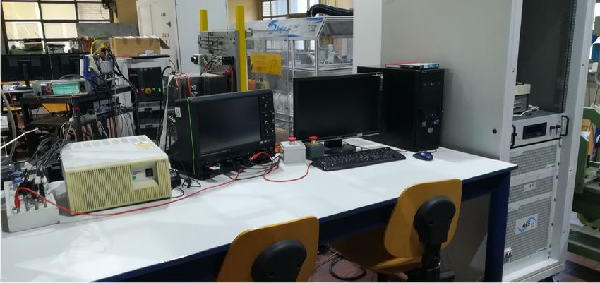
4. Experimental Validation
The proposed VSM-based control of the UFC station AFE has been implemented on
a 15 kVA grid-connected inverter to validate it experimentally. Figure 11 shows a picture
of the experimental setup. The DC source output voltage, representing the local storage
of the charging stations, is set to 400 V. The 50 kVA grid emulator provides a 220 VRMS
line-to-line grid voltage at 50 Hz. The controller (VSM + current control) is implemented
in C-code on a dSPACE 1005 controller. The control is executed at f s = 10 kHz, which
corresponds to the switching frequency f sw . The grid interface LCL filter parameters as
well as the S-VSC parameters are listed in Table 1.
Inverter LCL Filter
DC Source
dSPACE
Module
User Interface
Oscilloscope
Grid
Emulator
Figure 11. Adopted experimental setup for the validation of the proposed control features.World Electr. Veh. J. 2021, 12, 16 12 of 21
Table 1. Inverter and S-VSC parameters for the experimental tests.
Parameter Description Value
Vb base voltage 120 VRMS
Sb base power 15 kVA
f grid frequency 50 Hz
f sw , f s switching and control frequency 10 kHz
Lf LCL filter inverter-side inductance 545 µH
Cf LCL filter capacitance 22 µF
Lg LCL filter grid-side inductance 390 µH
Ls S-VSC virtual inductance 0.1 pu
Rs S-VSC virtual resistance 0.02 pu
H S-VSC virtual inertia constant 4s
τe S-VSC excitation time constant 1s
Lrq S-VSC virtual damper inductance 0.71 pu
τrq0 S-VSC virtual damper time constant 0.23 s
The performed tests are the following:
• Test 1: inertial contribution in response to a grid power unbalance;
• Test 2: reactive power reference step variation;
• Test 3: harmonic compensation;
• Test 4: voltage dip.
These tests demonstrate that the proposed control solution can provide the necessary
ancillary services to the grid. In particular, (1) it can support the grid frequency during load
unbalances, (2) it can contribute to the static voltage regulation by injecting reactive power,
(3) it provides a low impedance path for current harmonics, mitigating the grid voltage
distortion at the PCC and (4) it can provide dynamic reactive grid support by injecting
reactive fault current in case of voltage dips.
Finally, a comparison between the proposed solution and a Distribution Static Syn-
chronous Compensator (D-STATCOM) is also provided to demonstrate the superiority of
the proposed design.
4.1. Test 1: Inertial Action
The first test aims to prove the active support capabilities of the proposed solution.
This is done by emulating with the grid emulator a large load unbalance, representing the
loss of a large power generating unit. In the tested case, the grid frequency drops to the
frequency nadir of 48.7 Hz and then settles to the post fault value of 49.6 Hz. The frequency
variation is chosen to be larger than standard occurrences in order to magnify the effect of
the proposed solution. As it emerges from Figure 12a, the proposed solution effectively
injects active power proportionally to the inverse of the grid frequency derivative. The
active power injection stops as soon as the grid frequency settles to its final value of 49.6 Hz.
During the transient, the S-VSC does not lose synchronism with the grid and manages to
track its frequency in an accurate way.
A supplementary test is performed, applying the same frequency perturbation from
the grid emulator. In this case, a proportional frequency control (droop coefficient b = 5%)
is added externally, generating an active power reference equal to
ω ∗ − ωr
Pd = , (8)
b
where the setpoint ω∗ is set to the rated European frequency of 50 Hz. As shown in
Figure 12b, the S-VSC still contributes with inertial active power Pv exactly as in the
previous test. However, the total active power injected by the inverter P is now the sum
of Pv and the droop contribution Pd . This latter power term provides a static frequency
regulation and contributes to restoring it to the rated value. It must be noted that theWorld Electr. Veh. J. 2021, 12, 16 13 of 21
participation to primary frequency control (active droop) is usually an optional feature
and in the case of UFCs it could represent an additional stream of revenues after proper
agreements with the grid operator.
fr
DROOP
OFF
P
(a)
DROOP
P ON
(b)
inertial
action
Figure 12. Frequency regulation tests. (a) The S-VSC reacts to the grid frequency variation by
injecting active power into the grid during the transient (inertial behavior). (b) A droop control
reference is added in parallel to the S-VSC, injecting active power also after the frequency is settled.
4.2. Test 2: Reactive Power Generation
The proposed AFE control structure can also take part to the voltage regulation,
by injecting or absorbing reactive power. The static voltage regulation law has to be
implemented according to the grid standards (e.g., [38]) and generates a reactive power
reference Q∗ . The proposed control structure is able to track this reference as shown in
Figure 13. In this case, the reactive power reference Q∗ is changed from 0.3 pu to 0.4 pu.
The overall dynamic response depends on the tuning of the current controller and optional
filters, not being directly processed by the S-VSC.
step time
Q
Figure 13. Reactive power step response. This highlights the capability of injecting or absorbing
reactive power and therefore contributing to the regulation of the voltage.World Electr. Veh. J. 2021, 12, 16 14 of 21
4.3. Test 3: Harmonic Compensation
To prove the harmonic compensation capabilities, a distorted grid is generated by
means of the grid emulator. A 5 % 5-th harmonic voltage distortion is introduced. The
effect of the VSC is beneficial, as results from the DFT analysis presented in Figure 14. In
particular, the 5-th voltage harmonic is attenuated from 6 V to 4 V, proving the effectiveness
of the harmonic compensation feature.
CH 1
2 V/div
S-VSC
OFF
(a)
CH 1
2 V/div
S-VSC
ON
(b)
Figure 14. Harmonic compensation test. A 5 % 5-th harmonic component is introduced into the
emulated grid. A comparison with the S-VSC enabled and disabled is carried out: (a) DFT of the
voltage at the point of common coupling (PCC) when the S-VSC is off; (b) DFT of the voltage at the
PCC when the S-VSC is on.
4.4. Test 4: Fault Current Injection
The behavior in case of short circuits in the grid is tested by applying a voltage dip
from the grid emulator. The voltage dips are chosen according to statistical data available
in the technical standards [39]:
• Dip 1: −20 % and 300 ms duration;
• Dip 2: −20 % and 60 ms duration.
These can be representative of a fault in the medium- and high-voltage grid, respec-
tively. As it is shown in Figure 15, the AFE injects short circuit reactive current during the
fault for grid support and triggering of protection relays. Moreover, the reference current
is clamped to the limit value Imax (set to 36 A in such tests), meaning that the reactive
power is limited to 0.5 pu. This limitation is even clearer when looking at the amplitude of
the injected current, which is strongly limited to the design value of 36 A. The duration
of the current injection can be tuned by modifying the time constant τe of the excitation
control. The beneficial effect of the fault current injection is already visible in this test.
As mentioned, the voltage dip depth is 20 % in both dips. A starting voltage of 92% was
applied; therefore, the residual voltage would be equal to 72 % (with no reactive power
injection). However, the S-VSC reactive injection supports the voltage at the PCC and
increases it up to around 77% in both cases (see Figure 15), therefore proving the successful
grid supporting capabilities of a UFC equipped with the S-VSC.World Electr. Veh. J. 2021, 12, 16 15 of 21
Vg
λe
Q
–
|idq|
(a)
Vg λe
Q
–
|idq|
(b)
Figure 15. System response during Dip 1 (a) and Dip 2 (b), representative of a fault in the medium
and high voltage grid, respectively. The S-VSC injects reactive current to support the grid voltage
and trigger the protection relays.From top to bottom: (top) grid voltage amplitude Vg and virtual
excitation flux linkage λe of the S-VSC; (middle) reactive power Q injected by the S-VSC into the
grid; (bottom) amplitude of the current |idq | injected by the S-VSC into the grid.World Electr. Veh. J. 2021, 12, 16 16 of 21
4.5. Performance Comparison with D-STATCOM
In distribution systems, D-STATCOMs are employed to actuate static voltage regula-
tion [40,41]. Moreover, they can provide other ancillary services such as inertial support [42]
and harmonic compensation [43]. Therefore, the previous tests are repeated replacing the
AFE with a D-STATCOM in order to compare the behavior of the two solutions. These tests
are performed by means of simulations in PLECS environment.
4.5.1. Inertial Action
The hardware of conventional D-STATCOMs only features a capacitive DC-link,
with no energy storage, thus representing a strong limitation to the frequency support
capabilities. Therefore, traditional D-STATCOMs are not suitable to actuate frequency
regulation, neither inertial nor permanent, as demonstrated by the result of Test 1 (see
Figure 16).
fr
P
–
Figure 16. Simulated frequency regulation tests. The Distribution Static Synchronous Compensator
(D-STATCOM) does not react to the grid frequency variation.
Nevertheless, STATCOMs can be used to provide limited frequency regulation, by
adding suitable inertial controllers and allowing for the charging/discharging of the DC-
link capacitors. In particular, they can only operate in the first few ms of a load unbalance,
after which the DC-link capacitor voltage reaches critical levels and the inertial active power
can no longer be injected into the grid [42]. On the other hand, the solution proposed herein
is a VSC integrated into an ultra-fast charging station with local storage. As a consequence,
the frequency support is not limited to a short inertial action and is decoupled from the DC-
link capacitors, thanks to the energy storage system installed in the station. As previously
shown in Figure 12, the proposed S-VSC is both able to provide inertial support and
long-term frequency regulation, as opposed to the limited inertial action (i.e., at most) of
a STATCOM.
4.5.2. Reactive Power Generation and Fault Current Injection
In general, traditional STATCOM reactive controllers can be divided in two categories,
which employ different control strategies:
• Reactive Power Control: the STATCOM tracks an external reactive power reference,
coming, e.g., from the grid operator. Figure 17 shows the response of the D-STATCOM
for Test 2, where a reactive power step from 0.3 pu to 0.4 pu occurs. In this case, no
differences are identified between the D-STATCOM and the proposed S-VSC solution.World Electr. Veh. J. 2021, 12, 16 17 of 21
• AC Voltage Amplitude Control: a proportional integral (PI) voltage amplitude control
is implemented, generating the necessary reactive power references. This controller is
able to support the grid voltage during faults, by injecting reactive current. However,
in case of a permanent voltage dip, the injected current remains constant, as shown
in Figure 18. On the contrary, the results reported in Figure 19 demonstrate how the
S-VSC injects reactive fault current in the same way as a synchronous machine (i.e.,
exponential transient of the fault current).
step time
Q
Figure 17. Simulated reactive power step response of D-STATCOM. This highlights the capability of
injecting or absorbing reactive power and therefore contributing to the regulation of the voltage.
Therefore, D-STATCOMs are suitable for static reactive support, but they require
more advanced controllers to emulate the behavior of synchronous machines (e.g., fault
current shape). In fact, during voltage dips, the reactive short circuit current injected by the
D-STATCOM quickly grows and saturates and this solution cannot adapt to modified grid
voltage conditions, differently from the S-VSC. Nevertheless, from a hardware perspective,
a STATCOM could provide the same reactive performance of the proposed S-VSC solution;
however, it would require a modified control strategy.
Vg
Q
|idq|
Figure 18. Simulated D-STATCOM response to a 10 % permanent voltage dip: the injected current
remains constant after the fault.World Electr. Veh. J. 2021, 12, 16 18 of 21
Vg λe
Q
|idq|
(b)
Figure 19. Experimental S-VSC response to a 10 % permanent voltage dip: the injected current
follows the typical exponential profile of synchronous generators.
4.5.3. Harmonic Compensation
Traditional STATCOM controllers cannot provide harmonic compensation, as opposed
to the S-VSC solution. During Test 4, a 5 % 5-th harmonic distortion is added to the ideal
grid voltage. As shown in Figure 20, the D-STATCOM does not react, leaving unaltered the
distortion at the PCC. With the implementation of additional controllers, STATCOMs can
provide harmonic compensation [43], however affecting the controller complexity.
Figure 20. Simulated harmonic compensation test for D-STATCOM. A 5 % 5-th harmonic component
is introduced into the emulated grid and the STATCOM does not react.
4.5.4. Overview
It can be concluded that the proposed S-VSC control strategy applied to the AFE of a
bidirectional UFC station outperforms traditional D-STATCOMs, being able to condense
in a single controller all of the relevant grid ancillary services. The main advantage of the
proposed S-VSC solution resides in the integration of the S-VSC control into the existing
hardware of the charging station, therefore exploiting in a better way the power hardware
that is anyway installed. STATCOMs, on the other hand, are specific equipment for grid
support and require a dedicated and expensive installation, being only exploited for
compensation purposes.World Electr. Veh. J. 2021, 12, 16 19 of 21
5. Conclusions
This paper has proposed a VSC-based control of the grid-connected front-end of an
EV UFC station with integrated energy storage. The proposed control solution strongly
improves the behavior of the charging station from the utility point of view, providing the
following grid ancillary services:
• frequency support with inertial action;
• reactive power generation for grid voltage support;
• harmonic compensation;
• fault current injection in case of grid-side faults to trigger the utility protections.
The provision of such services can be both beneficial from a technical stand-point
(i.e., supporting the stability of the grid) and from an economical point of view, if new
regulations are implemented. With such new regulations, the contribution of EV charging
stations to grid ancillary services could be remunerated, and consequently generate an
additional profit stream for the station operators.
The proposed S-VSC control strategy has been validated experimentally and has been
shown to outperform traditional D-STATCOMs. The proposed charging station concept
can effectively support the grid when needed, therefore representing a viable solution for a
simpler integration of UFCs into the power distribution grid.
Author Contributions: Conceptualization, F.M. and D.C.; methodology, F.M. and D.C.; software,
F.M. and V.M.; validation, F.M. and V.M.; formal analysis, F.M., D.C. and V.M.; investigation, F.M.,
D.C. and V.M.; resources, F.M and R.B.; data curation, F.M., D.C. and V.M.; writing—original draft
preparation, F.M. and D.C.; writing—review and editing, F.M., D.C., V.M. and R.B.; visualization,
D.C.; supervision, F.M. and R.B.; project administration, F.M. and R.B.; funding acquisition, R.B. All
authors have read and agreed to the published version of the manuscript.
Funding: This research was funded by the Power Electronics Innovation Center (PEIC) of Politecnico
di Torino.
Conflicts of Interest: The authors declare no conflict of interest.
References
1. Manzetti, S.; Mariasiu, F. Electric Vehicle Battery Technologies: From Present State to Future Systems. Renew. Sustain. Energy Rev.
2015, 51, 1004–1012. [CrossRef]
2. Clement-Nyns, K.; Haesen, E.; Driesen, J. The Impact of Charging Plug—In Hybrid Electric Vehicles on a Residential Distribution
Grid. IEEE Trans. Power Syst. 2010, 25, 371–380. [CrossRef]
3. Tu, H.; Feng, H.; Srdic, S.; Lukic, S. Extreme Fast Charging of Electric Vehicles: A Technology Overview. IEEE Trans. Transp.
Electrif. 2019, 5, 861–878. [CrossRef]
4. Nicholas, M.; Hall, D. Lessons Learned on Early Electric Vehicle Fast-Charging Deployments; International Council on Clean
Transportation: Washington, DC, USA, 2018; p. 54.
5. IEA. Global EV Outlook 2020—Analysis; IEA: Paris, France, 2020.
6. Khaligh, A.; Dusmez, S. Comprehensive Topological Analysis of Conductive and Inductive Charging Solutions for Plug-In
Electric Vehicles. IEEE Trans. Veh. Technol. 2012, 61, 3475–3489. [CrossRef]
7. Yilmaz, M.; Krein, P.T. Review of Battery Charger Topologies, Charging Power Levels, and Infrastructure for Plug-In Electric and
Hybrid Vehicles. IEEE Trans. Power Electron. 2013, 28, 2151–2169. [CrossRef]
8. Gautam, D.S.; Musavi, F.; Edington, M.; Eberle, W.; Dunford, W.G. An Automotive Onboard 3.3-kW Battery Charger for PHEV
Application. IEEE Trans. Veh. Technol. 2012, 61, 3466–3474. [CrossRef]
9. Cittanti, D.; Gregorio, M.; Mandrile, F.; Bojoi, R. Full Digital Control of an All-Si On-Board Charger Operating in Discontinuous
Conduction Mode. Electronics 2021, 10, 203. [CrossRef]
10. Channegowda, J.; Pathipati, V.K.; Williamson, S.S. Comprehensive Review and Comparison of DC Fast Charging Converter
Topologies: Improving Electric Vehicle Plug-to-Wheels Efficiency. In Proceedings of the IEEE International Symposium on
Industrial Electronics (ISIE), Buzios, Brazil, 3–5 June 2015; pp. 263–268. [CrossRef]
11. Aggeler, D.; Canales, F.; Zelaya-De La Parra, H.; Coccia, A.; Butcher, N.; Apeldoorn, O. Ultra-Fast DC-Charge Infrastructures for
EV-Mobility and Future Smart Grids. In Proceedings of the IEEE PES Innovative Smart Grid Technologies Conference Europe
(ISGT Europe), Gothenberg, Sweden, 11–13 October 2010. [CrossRef]
12. Srdic, S.; Lukic, S. Toward Extreme Fast Charging: Challenges and Opportunities in Directly Connecting to Medium-Voltage
Line. IEEE Electrif. Mag. 2019, 7, 22–31. [CrossRef]World Electr. Veh. J. 2021, 12, 16 20 of 21
13. Shareef, H.; Islam, M.M.; Mohamed, A. A Review of the Stage-of-the-Art Charging Technologies, Placement Methodologies, and
Impacts of Electric Vehicles. Renew. Sustain. Energy Rev. 2016, 64, 403–420. [CrossRef]
14. Ma, C.T. System Planning of Grid-Connected Electric Vehicle Charging Stations and Key Technologies: A Review. Energies 2019,
12, 4201. [CrossRef]
15. Negarestani, S.; Fotuhi-Firuzabad, M.; Rastegar, M.; Rajabi-Ghahnavieh, A. Optimal Sizing of Storage System in a Fast Charging
Station for Plug-in Hybrid Electric Vehicles. IEEE Trans. Transp. Electrif. 2016, 2, 443–453. [CrossRef]
16. Oureilidis, K.; Malamaki, K.N.; Gallos, K.; Tsitsimelis, A.; Dikaiakos, C.; Gkavanoudis, S.; Cvetkovic, M.; Mauricio, J.M.;
Maza Ortega, J.M.; Ramos, J.L.M.; Papaioannou, G.; Demoulias, C. Ancillary Services Market Design in Distribution Networks:
Review and Identification of Barriers. Energies 2020, 13, 917. [CrossRef]
17. Kundur, P. Power System Stability and Control; McGraw-Hill Education: New York City, NY, USA, 1994.
18. Kirschbaum, E. Germany to Close all 84 of Its Coal-Fired Power Plants, will Rely Primarily on Renewable Energy; Los Angeles Times:
El Segundo, CA, USA, 2019.
19. Urdal, H.; Ierna, R.; Zhu, J.; Ivanov, C.; Dahresobh, A.; Rostom, D. System Sstrength Considerations in a Converter Dominated
Power System. IET Renew. Power Gener. 2015, 9, 10–17. [CrossRef]
20. Beck, H.; Hesse, R. Virtual Synchronous Machine. In Proceedings of the International Conference on Electrical Power Quality
and Utilisation (EPCU), Barcelona, Spain, 9–11 October 2007. [CrossRef]
21. Tamrakar, U.; Shrestha, D.; Maharjan, M.; Bhattarai, B.P.; Hansen, T.M.; Tonkoski, R. Virtual Inertia: Current Trends and Future
Directions. Appl. Sci. 2017, 7, 654. [CrossRef]
22. Chen, M.; Zhou, D.; Blaabjerg, F. Modelling, Implementation, and Assessment of Virtual Synchronous Generator in Power
Systems. J. Mod. Power Syst. Clean Energy 2020, 8, 399–411. [CrossRef]
23. Yan, X.; Zhang, W. Review of VSG Control-Enabled Universal Compatibility Architecture for Future Power Systems with
High-Penetration Renewable Generation. Appl. Sci. 2019, 9, 1484. [CrossRef]
24. Kesler, M.; Kisacikoglu, M.C.; Tolbert, L.M. Vehicle-to-Grid Reactive Power Operation Using Plug-In Electric Vehicle Bidirectional
Offboard Charger. IEEE Trans. Ind. Electron. 2014, 61, 6778–6784. [CrossRef]
25. Yong, J.Y.; Ramachandaramurthy, V.K.; Tan, K.M.; Mithulananthan, N. Bi-Directional Electric Vehicle Fast Charging Station with
Novel Reactive Power Compensation for Voltage Regulation. Int. J. Electr. Power Energy Syst. 2015, 64, 300–310. [CrossRef]
26. Dhingra, K.; Singh, M. Frequency Support in a Micro-Grid Using Virtual Synchronous Generator Based Charging Station. IET
Renew. Power Gener. 2018, 12, 1034–1044. [CrossRef]
27. Suul, J.A.; D’Arco, S.; Guidi, G. Virtual Synchronous Machine-Based Control of a Single-Phase Bi-Directional Battery Charger for
Providing Vehicle-to-Grid Services. IEEE Trans. Ind. Appl. 2016, 52, 3234–3244. [CrossRef]
28. Yan, X.; Li, J.; Zhang, B.; Jia, Z.; Tian, Y.; Zeng, H.; Lv, Z. Virtual Synchronous Motor Based-Control of a Three-Phase Electric
Vehicle Off-Board Charger for Providing Fast-Charging Service. Appl. Sci. 2018, 8, 856. [CrossRef]
29. Cittanti, D.; Gregorio, M.; Bojoi, R. Digital Multi-Loop Control of a 3-Level Rectifier for Electric Vehicle Ultra-Fast Battery
Chargers. In Proceedings of the AEIT International Annual Conference (AEIT), Catania, Italy, 23–25 September 2020. [CrossRef]
30. Cittanti, D.; Gregorio, M.; Armando, E.; Bojoi, R. Digital Multi-Loop Control of an LLC Resonant Converter for Electric Vehicle
DC Fast Charging. In Proceedings of the IEEE Energy Conversion Congress and Exposition (ECCE), Detroit, MI, USA, 11–15
October 2020; pp. 4423–4430. [CrossRef]
31. Cittanti, D.; Vico, E.; Gregorio, M.; Mandrile, F.; Bojoi, R. Iterative Design of a 60 kW All-Si Modular LLC Converter for Electric
Vehicle Ultra-Fast Charging. In Proceedings of the AEIT International Conference of Electrical and Electronic Technologies for
Automotive (AEIT AUTOMOTIVE), Torino, Italy, 18–20 November 2020.
32. Liserre, M.; Blaabjerg, F.; Hansen, S. Design and Control of an LCL-Filter-Based Three-Phase Active Rectifier. IEEE Trans. Ind.
Appl. 2005, 41, 1281–1291. [CrossRef]
33. Cittanti, D.; Mandrile, F.; Bojoi, R. Optimal Design of Grid-Side LCL Filters for Electric Vehicle Ultra-Fast Battery Chargers.
In Proceedings of the International Universities Power Engineering Conference (UPEC), Torino, Italy, 1–4 September 2020.
[CrossRef]
34. Tahir, S.; Wang, J.; Baloch, M.H.; Kaloi, G.S. Digital Control Techniques Based on Voltage Source Inverters in Renewable Energy
Applications: A Review. Electronics 2018, 7, 18. [CrossRef]
35. Teodorescu, R.; Liserre, M.; Rodriguez, P. Grid Converters for Photovoltaic and Wind Power Systems; John Wiley & Sons: Hoboken,
NJ, USA,2011.
36. Mandrile, F.; Carpaneto, E.; Armando, E.; Bojoi, R. Simple Tuning Method of Virtual Synchronous Generators Reactive Control.
In Proceedings of the 2020 IEEE Energy Conversion Congress and Exposition (ECCE), Detroit, MI, USA, 11–15 October 2020; pp.
2779–2785. [CrossRef]
37. Mandrile, F.; Carpaneto, E.; Bojoi, R. Grid-Feeding Inverter with Simplified Virtual Synchronous Compensator Providing Grid
Services and Grid Support. IEEE Trans. Ind. Appl. 2020, 57, 559–569. [CrossRef]
38. VDE. VDE-AR-N 4120—Connection and Operation to High-Voltage Grid and Their Operation; VDE: Frankfurt am Main,
Germany, 2018.
39. IEC. IEC TR 61000–61002-8:2002—Electromagnetic compatibility (EMC)—Part 2-8: Environment—Voltage Dips and Short Interruptions
on Public Electric Power Supply Systems with Statistical Measurement Results; IEC: Geneva, Switzerland, 2002.You can also read