City of Kitchener Development Services Department Engineering Services Constructed Asset Data Submission User Manual for Engineering - Revised: ...
←
→
Page content transcription
If your browser does not render page correctly, please read the page content below
City of Kitchener
Development Services Department
      Engineering Services

Constructed Asset Data Submission
   User Manual for Engineering

        Revised: April 11, 2018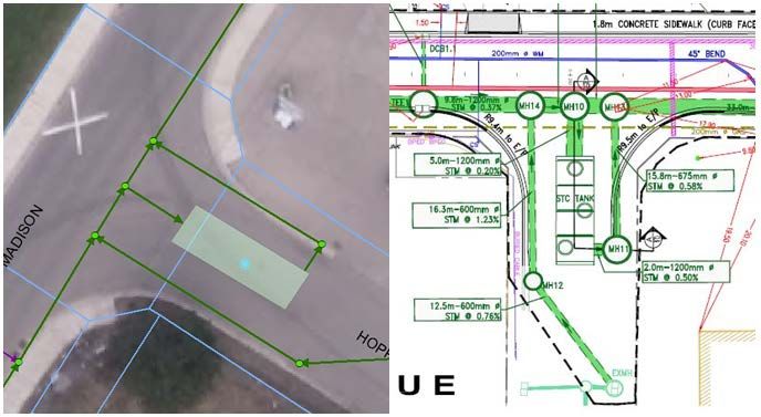
City of Kitchener Constructed Asset Data Submission User Manual for Engineering

Revision History

Revision Description                                                       Date
Initial draft for review                                                   September 10, 2010
Final draft revisions                                                      September 13, 2010
Requirements updates                                                       Dec 14, 2010
Tracking form revisions                                                    September 29, 2011
Tracking form revisions                                                    March 15, 2012
Requirements updates                                                       October 2, 2012
Tracking form revisions                                                    October 2, 2012
User manual revisions                                                      October 2, 2012
FAQ updates                                                                November 29, 2012
User manual revisions                                                      February 1, 2013
Template revisions                                                         February 1, 2013
Template revisions                                                         March 10, 2016
User manual revisions                                                      December 2, 2016
Template revisions                                                         November 10, 2017
Template revisions                                                         April 9, 2018
User manual revisions                                                      April 11, 2018

                                                                                                        2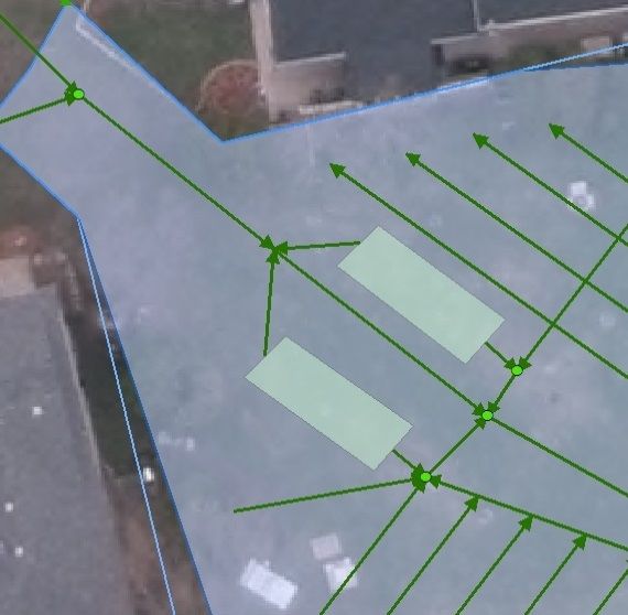
City of Kitchener
                                    Development Services Department
                                          Engineering Services

                                  Constructed Asset Data Submission
                                     User Manual for Engineering

                                                       Table of Contents

1.0 BACKGROUND................................................................................................................................. 4
2.0 CONSTRUCTED ASSET DATA DEFINITIONS .......................................................................... 4
3.0 RECORDING ASSET INFORMATION .......................................................................................... 5
  3.1) Storm Water Assets .................................................................................................................. 5
  3.2) Culverts/Bridges......................................................................................................................... 8
  3.3) Stormwater Management Facilities ....................................................................................... 8
4.0 REQUIREMENTS FOR APPROVAL ............................................................................................. 9
APPENDIX A .......................................................................................................................................... 10
Constructed Assets Data Submission FAQ ....................................................................................... 10
APPENDIX B .......................................................................................................................................... 16
Drawing Examples ................................................................................................................................. 16
Table 1 - Stormwater Facility Layers (as of April 2018) ................................................................... 18
Sample Constructed Asset Data Drawing (Previous method using an Excel form)................... 21
APPENDIX C .......................................................................................................................................... 22
Constructed Asset Data (SDF) Format ............................................................................................... 22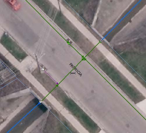
City of Kitchener Constructed Asset Data Submission User Manual for Engineering

1.0 BACKGROUND

In 2010, data submission requirements have been further defined as part of the City of
Kitchener Development Manual. All City of Kitchener owned infrastructure assets must be
reported in accordance to the standards defined within the City of Kitchener Constructed Asset
Data Submission User Manual (for Engineering).

In addition to “As Recorded” drawings, a separate AutoCAD file, called the “Constructed
Assets Drawing” must be completed and submitted to respective City of Kitchener Engineering
Project Staff, who will then submit to GIS for further error checking. Constructed Asset Data
submission requirements pertain to all Site Plans, Subdivisions, New Construction, and
Reconstruction Projects.

The Consultant shall refer to the Development Manual webpage to download the latest forms,
manuals, and frequently asked questions. Commencing March 2013, AutoCAD drawings in the
City’s Spatial Data Format (SDF) should be submitted.

Link to Development Manual Webpage:
http://kitchener.ca/en/businessinkitchener/Development_manual.asp

2.0 CONSTRUCTED ASSET DATA DEFINITIONS

As-Recorded Drawing: refers to digital CAD drawing that contains all built information as per
design.

Constructed Asset Drawing: refers to the digital CAD drawing that shows all constructed
infrastructure, containing both appropriate graphics and attributes for each asset type. Refer to
Appendix A in this document and the CAD Checker, Field and Pick List Definitions April 2015
(.xls) document online.

Culvert: an asset that conveys open surface water features to open surface water features
perpendicular to the roadway. See Appendix B.

Inlet: an asset that feeds into a closed network from a storm water facility regardless if it is a
catch basin. See Appendix B.

Outlet: an asset that terminates into open watercourse (i.e. ponds, ditches, creeks). See
Appendix B.

SDF: Spatial Data file format for Autodesk GIS programs. Submitting constructed asset data in
this format reduces the need for the Excel spreadsheet. All asset information is attached to
each of the layers in the drawing.

                                                                                                                       4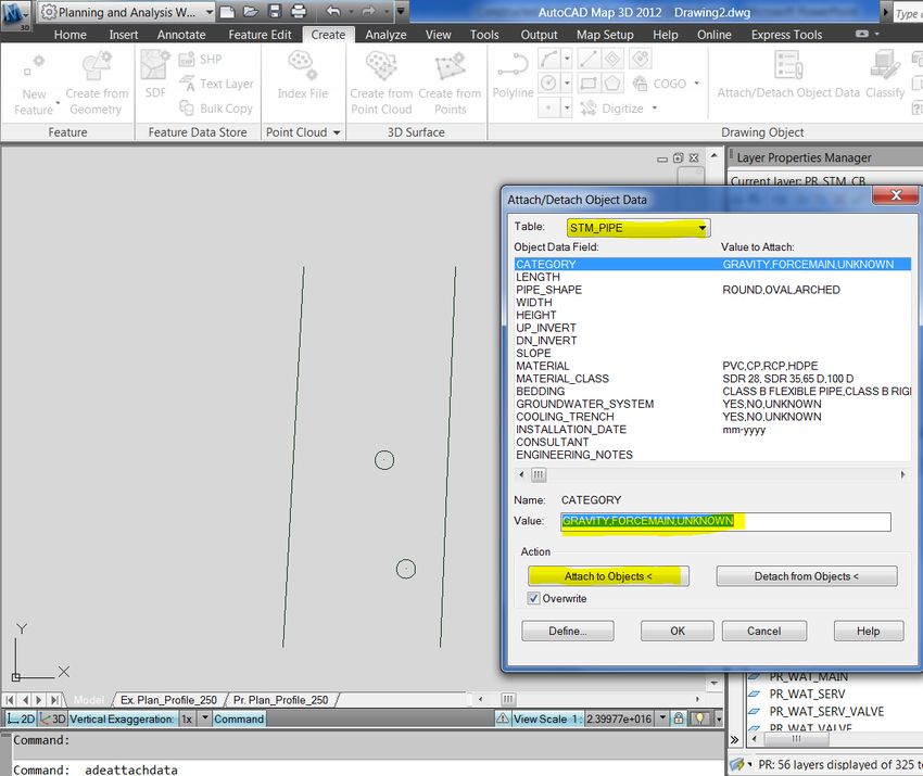
City of Kitchener Constructed Asset Data Submission User Manual for Engineering

Storm Service: an asset that moves storm water from private to public property, even if there
is a manhole at the main connection to private property. See Appendix A.

Storm/Sanitary Pipe: an asset responsible for main network conveyance from manhole to
manhole. See Appendix A.

3.0 RECORDING ASSET INFORMATION

Commencing March 2013, AutoCAD drawings in the City’s Spatial Data Format (SDF) should be
submitted.

Refer to Appendix C for instructions on creating drawings in Spatial Data File Format (SDF). The
SDF drawing completely replaces the previous method, which included an Excel tracking form
and simplified CAD drawing.

Information should contain proposed infrastructure within the right of way (or up to property line), with
the exception for Stormwater Management Facilities: Ponds, Infiltration Galleries, and OGS units. ALL
storm water management facilities both private and publicly owned must be documented (for the Storm
Water Management Audit).

All form areas must be complete if corresponding infrastructure was constructed, with the exception of
bridges or culverts 3m or greater, which will require an Ontario Structure Inspection Manual (OSIM)
standard form (pages 1 and 4 only).

Installation dates must be filled out if construction will not be completed by City forces. For
subdivisions, sidewalk installation dates can be left blank on the form, and will coincide with the date of
final acceptance. For site plans, all installation dates can be left blank.

       3.1) Storm Water Assets

   a. In locations where STM_PIPE / STM_LEADS drain into the culvert (blind taps) we will
      split the culvert polyline at that point.

                                                                                                                          5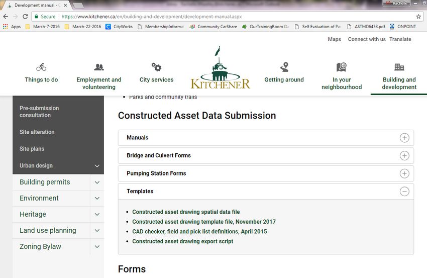
City of Kitchener Constructed Asset Data Submission User Manual for Engineering

           Illustration: Correct Symbolization: Culvert along with STREAM_REACH snap into inlet and outlet. Also shows the
culvert being split at the location where STM_PIPEs and a STM_LEAD tap into the culvert. Flow of culvert also matches up with
                                            engineering plan and direction of streams

   a. Each Kitchener owned holding tank structure should be symbolized with a polygon
      (Still need to create layer). For OnPoint this polygon should be partly transparent
      polygon that shows the proper foot print of the holding tank.
   b. Ensure that the Stm_Pipes that lead into and out of the holding tanks snap to the ends
      of the polygons to ensure connectivity.
   c. The storm pipes entering and exiting the holding tank should retain their true lengths
      and locations
   d. OGS Holding Tank need to include an OGS point in the middle of the holding tank
      polygon. Ensure these points are listed as CATEGORY: “HOLDING TANK” in the OGS
      layer attribute table.

                                                                                                                                 6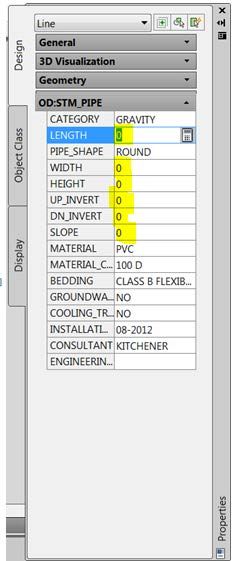
City of Kitchener Constructed Asset Data Submission User Manual for Engineering

Illustration: Holding tank with the proper footprint according to the plans and storm pipes snapping to the polygons
                                                to ensure connectivity.

Illustration: Same as the holding tank example on the previous page except for the added OGS point symbol that is needed for all
                                                      OGS holding tanks.

   a. All infiltration galleries should be symbolized with a polygon. Previously we also used
      points but this should no longer be used.
   b. All touching infiltration gallery polygons should be merged together into one large
      polygon.
   c. Ensure we show all pipes / subsurface chambers that run through the infiltration
      galleries, these will be symbolized in the storm pipe layer.

                                                                                                                                  7
City of Kitchener Constructed Asset Data Submission User Manual for Engineering

d. There should be no splitting of Storm Pipes at vertical pipe bends (slope changes) for a
   storm pipe.
e. There should be no splitting of Storm Pipes at horizontal pipe bends for a storm pipe.
f. When small sections of a pipe are replaced during a reconstruction job, we do not want
   to show the break and multiple small sections. Instead examine the multiple sections of
   pipes between the two storm manholes. Merge the multiple sections of pipes and keep
   the attribute information (material type / installation date / etc.) from the largest section
   of pipe. Attributes such as; Length / slope / up and down manhole / etc. should be
   recalculated / updated.

   3.2) Culverts/Bridges

If the internal diameter of a storm culvert is 3000mm or greater then it is considered a
bridge. A bridge inspection must be completed in accordance to the Ontario Structural
Inspection Manual (OSIM), see Figure 7. Page 1 to be completed per bridge and Page 4
to be completed per bridge element. Forms can be saved by printing to PDF.

   3.3) Stormwater Management Facilities

 The stormwater management facilities (SWM facilities) can consist of dry facilities or wet
 facilities with or without forebays. For the constructed asset drawing, the SWM facilities
 have the following layers; STM_FACILITY, STM_FOREBAY and STM_MAIN_POND. All
 these layers need to be drawn as a closed polygon.

 1) STM_FACILITY – The fields for this layer are related to the design of the overall facility.
     This is represented as a polyline around the SWM block.
 2) STM_FOREBAY – These fields are specifically related to the forebay of the facility.
     This is represented as a polyline around the permanent pool of the forebay. Where
     multiple forebays exist, a separate forebay polyline is used around both forebays with
     the respective data filled in.
 3) STM_MAIN_POND – These fields are specifically related to the main cell of the facility.
     This is represented by a polyline around the permanent pool of the main cell. If no
     forebay exists with the facility, this layer would be used for the whole facility. If no
     permanent pool exists, the polyline for this layer would around the outline of the
     extended storage elevation.

 Proper representation of these layers is presented in Appendix B. All stormwater
 management facilities are to consist of a pond inlet, (stormwater flows out of the storm
 sewer network and into the pond), and a pond outlet (stormwater that leaves the pond
 through a series of pipes.)

                                                                                                                   8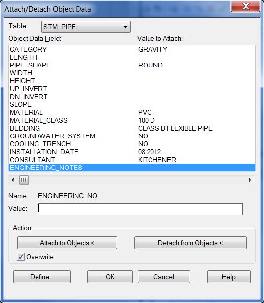
City of Kitchener Constructed Asset Data Submission User Manual for Engineering

  1) STM_INLET – This is represented in the constructed asset drawing as a point and is
      added to the upstream entrance of a storm pipe or culvert indicating the direction of
      flow. Examples of this point found at stormwater facilities are Hickenbottoms, CSP
      risers, DICBs and headwalls. Therefore, these would be found at the facility outlet
      (where stormwater leaves the facility.)
  2) STM_OUTLET – This is represented as a point and is snapped to the outfall of a
      storm pipe where stormwater leaves the pipe network. Examples of this point found a
      stormwater facilities are endwalls where the pipe network enters into the pond, and
      also at the outfall of the stormwater facility outlet.

  All storm pipe networks including individual culverts must have a STM_INLET and
  STM_OUTLET which represents the flow direction. The STM_INLET is at the upstream
  end of the pipe network and the STM_OUTLET must be at the downstream end of the
  pipe network. All storm pipe networks must also be drawn in direction of flow (beginning
  with upstream location to downstream location.)

4.0 REQUIREMENTS FOR APPROVAL

  For Site Plans, Constructed Asset Data Drawings must be submitted as part of the Site
  Plan Approval Process.

  For Reconstruction and New Construction projects, Constructed Asset Data Drawings must
  be submitted no later than 3 months following Substantial Performance.

  For Subdivisions, Constructed Asset Data Drawings must be submitted within 3 months of
  initial acceptance.

  If any information from any submission is incorrect or incomplete the City reserves the right
  to reject the submission and the Subdividers shall be required to resubmit the corrected
  submission prior to acceptance of the Maintenance Package.

                                                                                                                    9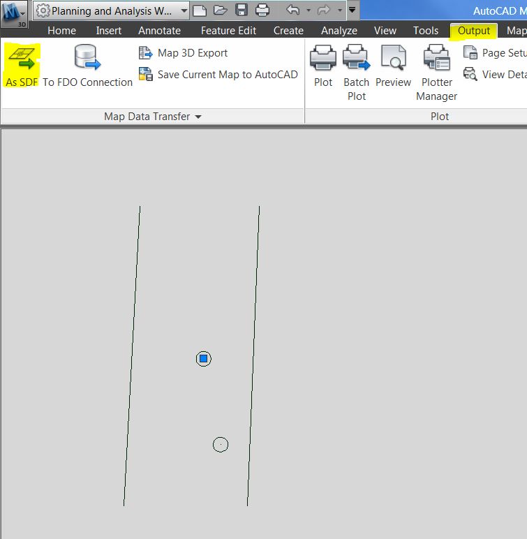
City of Kitchener Constructed Asset Data Submission User Manual for Engineering

                                                   APPENDIX A

                                 Constructed Assets Data Submission FAQ

1.0   General
2.0   Benchmark
3.0   Bridge/Cuvlert
4.0   Road
5.0   Sidewalk
6.0   Stormwater/Groundwater Sewer System
7.0   Sanitary Sewer System
8.0   Water System

                                                    1.0 General

How should I refer to the documents required for the data submission?

        The digital AutoCAD drawing is called the Constructed Asset Drawing. See Appendix B and C.

        The digital excel form is referred to the Constructed Assets Tracking Form. See figure 1 in the Constructed Asset
        Tracking Form Manual

What is the difference between the As-Recorded drawing and the Constructed Asset Drawing?

        The as-recorded drawing shows everything proposed and constructed. The constructed asset drawing must use City
        layer name standards and must be drawn to City standards. The constructed asset drawing is used for the purpose of
        importing information into our Geographic Information Systems (GIS). Refer to individual infrastructure sections in
        Appendix A for further details.

In which UTM coordinate system (ground or grid) should the Constructed Assets drawing be
provided?

        Grid.

For ‘As-Recorded’ drawing submissions, when translating the drawing to UTM NAD 83 Zone 17
coordinates, is it sufficient to get the UTM coordinates from Google Earth or OBM Mapping?
What does the accuracy need to be? Or does the City have UTM coordinates (mapping) available
for the City? Or do we need to use GPS to get the most accurate coordinates?

        It should be GPS or surveyed and translated to UTM NAD 83 Zone 17 coordinates. If the project is a reconstruction
        and the consultant is working for the city we can provide Teranet land parcel information. If it is a subdivision they
        do have the option of purchasing the land parcel from Teranet but we cannot provide the data as part of our 3rd party
        agreement.

        Accuracy should be to the POLARIS standard.

                                                                                                                               10
City of Kitchener Constructed Asset Data Submission User Manual for Engineering
Would the City consider using AIA National CAD standards?
At this time, no. The City currently has a layering system in place that is familiar to internal and some external
stakeholders.
Plotting – Color dependent vs. Name dependent?
For development projects (i.e. site plans, subdivisions) this is irrelevant.
Capital and development charge projects should be name dependent as per the supplied file on the website.
Are consultants required to use the City’s standard layers and blocks for the As-Recorded
Drawing?
These are not required for this drawing.
Does a separate digital constructed assets watermain drawing need to be provided to Kitchener
Utilities?
No, the As-Recorded watermain ties and information drawing can be combined with the As-Recorded and
Constructed Assets drawings.
Is the Consultant required to complete field surveys in City layers?
No, the Consultant may proceed through the data collection and design stage using their layer standards.
Who at the City is creating and maintaining Civil3D standards and styles?
The Design and Approvals Section within the Engineering Division retains this task.
How do I know I have the latest version of the tracking form?
The latest version will always be available for download on the City of Kitchener’s website.
Where can I find the Constructed Assets Form and Manual?
On the City’s website at: http://www.kitchener.ca/en/businessinkitchener/Development_manual.asp
How can I get parcel fabric data?
If the consultant is doing a Capital Works project for the City, City (GIS) will provide Teranet information (property
fabric) as requested. If the project is development related, consultant must contact Teranet to purchase land Parcels
the city is under a 3rd party agreement with Teranet and can not resell their data.
How much lot fabric do I need to show in the assets drawing?
The amount of lot fabric required is such that the assets drawing can be verified to match the City’s parcel fabric.
The minimum acceptable amount of lot fabric would be the limits of the road right-of-way.
11City of Kitchener Constructed Asset Data Submission User Manual for Engineering
Can I submit a shapefile instead of the assets drawing and tracking form?
Currently the City does not accept submissions of the Constructed Assets drawing in shape file format. Another
format we are accepting is a Spatial Data File (SDF), which can be created using AutoCAD Civil 3D or AutoCAD
with Map3D. This removes the need to use the MS Excel spreadsheet and attach asset information to individual
assets in the drawing. Refer to section 5.0 of the Constructed Asset Tracking Form Manual.
What font properties should the asset ID labels have?
ID labels should be text objects and are preferred to be center justified and placed on the insertion point (or centre)
of the structure. The recommended text size is 0.8 units.
Should ID labels be on one text layer or one text layer per asset layer?
Either way is acceptable as long as all id text fit well together and is legible.
Which drawing needs to have the asset IDs in order to match the Asset tracking form?
Only the Constructed Assets drawing is required to have asset IDs, the As-Recorded drawing does NOT require
asset ID’s.
Site Plans do not have constructed assets, what should I do?
Constructed Assets drawings for Site plans should include any proposed service connections within the right of way
and ALL stormwater facilities, OGS, and infiltration galleries on site (for the purpose of either quantity or quality).
Refer to section 4.3 of the Constructed Asset Tracking Form Manual.
When am I required to submit the Constructed Assets drawing and tracking form?
This data submission is required prior to the first letter of credit reduction, as outlined in Section A.9.4 of the
Development Manual.
If there are styles with layers attached, they will not purge out, should all of the styles and extra
layers be purged on the template?
We are informing our reviewers that there may be extra layers and that it is ok, as long as the data in relevant layers
are correct. This will be considered in future updates to the template.
When importing the data from C3D to the drawing you are using the outer diameter and not the
inner diameter. Does the outer diameter not have the wall thickness? And this will give the
incorrect data?
Any diameter figures will be referenced as an inner diameter.
Should we not be importing the manhole numbers and pipe numbers, there is no way to tell the
consultant which manhole or pipe has issues without this.
This is not necessary, eventually the automatic CAD checker will provide a visual report of any issues within the
drawing.
12City of Kitchener Constructed Asset Data Submission User Manual for Engineering
If the information is from C3D and there is another field inside the table do we need to fill in the
table?
No, our process will be able to pick up information that comes from C3D so you can leave the one in our table
blank.
2.0 Benchmark
When do you require geodetic benchmark information?
Geodetic benchmark information is not required in the spreadsheet, unless there are new benchmarks installed as a
part of the work that the consultant has undertaken through the design process.
3.0 Bridges/Culverts
How are bridges / culverts to be drawn in the Constructed Assets Drawing?
The centerline of the bridge / culvert should be used to represent this feature. The centerline for bridges will be
drawn parallel to the span of the bridge, for culverts the centerline will be drawn perpendicular to the span of the
culvert.
Where do I provide Constructed asset data for a bridge or a culvert with a span of 3m or greater?
New bridges require pages 1 and 4 of the Ministry of Transportation’s Ontario Structure Inspection Manual (OSIM)
to be filled out. A copy of page 4 needs to be filled out for each bridge element, e.g. abutments, deck, approaches,
railings.
4.0 Road
What is required to be shown in the Constructed Assets drawing for roads?
The edge of pavement, curbs and road centreline shall be shown.
Where road widths vary the average width shall be used.
This is to be drawn from intersection to intersection.
5.0 Services
How will services with different material types or some other attribute be differentiated?
13City of Kitchener Constructed Asset Data Submission User Manual for Engineering
The Asset ID labels will differentiate between different types of services. E.g. If there are 100 water services, 80 of
them that are 25mm copper could all be labeled as WSER1 and 20 that are 50mm PE could all be labeled as
WSER2.
Services are to be drawn as a single line from the main to the property.
Does service lateral information for site plan service connections get recorded?
Yes. The City relies on the Consultant’s Constructed Assets drawing for providing our database with information
for site plan service connections installed by City staff.
6.0 Sidewalk
What is required for sidewalks in the Constructed Assets drawing?
A line / polyline / polygon to represent the outline of the sidewalk is acceptable.
7.0 Stormwater/Groundwater Sewer System
Do all stormwater / groundwater collection pipes to be drawn in the direction of flow?
Yes.
Stormwater pipes are to be drawn as a single line from manhole to manhole.
How are stormwater inlets/outlets to be drawn in the Constructed Assets Drawing?
It is important to note that inlets and outlets are drawn with respect to the stormwater pipe network. See drawing
samples in Appendix B
Where do I record Groundwater collection system assets?
Assets part of the groundwater management system (GWMS) shall be entered in the storm tab section of the asset
tracking form. “GWMS” should be noted in the engineering notes section of the tracking form.
Where do I record cooling trenches?
In the storm tab within the pipe section. “Cooling Trench” should be noted in the engineering notes section of the
tracking form.
If both a local and trunk sewer is present how is that to be shown on the drawing?
If the local and trunk sewer lay on the same vertical plane it can be represented as two lines with an offset of 0.5m.
What does “depth” refer to in the asset tracking form?
14City of Kitchener Constructed Asset Data Submission User Manual for Engineering
“Depth” is a reference to the difference in elevation from top of the structure to the lowest invert elevation.
8.0 Sanitary Sewer System
Do we need all sanitary pipes to be drawn in the direction of flow?
Yes.
Stormwater pipes are to be drawn as a single line from manhole to manhole.
If both a local and trunk sewer is present how is that to be shown on the drawing?
If the local and trunk sewer lay on the same vertical plane it can be represented as two lines with an offset of 0.5m.
9.0 Water System
Do you require watermain fittings in the drawing even if it is not mentioned in the tracking form?
Yes. The PR_WAT_OTHER layer pertains to: Crosses, Plug, Reducers, Tees, Transitions, and Vertical Bends.
Do we need to include watermain ties/dimensions?
Yes, on a separate layer called PR_WAT_TIES.
How are we to draw watermain segments?
Watermain segments are to be drawn as a single line and are to be broken up under these conditions:
• There is a change in any attribute (diameter, material, installation date, etc…). There might be a reducer,
transition or other type of feature between these mains if needed.
• At tees or crosses for the mains only. Tees off of the main for hydrants or services are not a cause for
breaking a water main as these are service pipes.
• At a change in road segment (intersection to intersection). Usually there is a tee or cross at the change in
road segment already, but there are instances where the road changes and there are no tees or crosses.
15City of Kitchener Constructed Asset Data Submission User Manual for Engineering
APPENDIX B
Drawing Examples
Figure 1 - Culvert Example
Open to Open = Culvert
16City of Kitchener Constructed Asset Data Submission User Manual for Engineering
Figure 2 - Outlet Example
Closed to Open = Outlet
Closed to Closed = Pipe
Open to Closed = Inlet
Open to Open = Outlet
17City of Kitchener Constructed Asset Data Submission User Manual for Engineering
Figure 3 - Stormwater Facility Example *background drawing for reference only
18City of Kitchener Constructed Asset Data Submission User Manual for Engineering
Table 1 - Stormwater Facility Layers (as of April 2018)
STM_FACILITY
STM FACILITY FIELD NAME PICK LIST VALUES NOTES FOR CONSULTANT
SUBWATERSHED Input the subwatershed name that the SWM facility is located in
BASIC, NORMAL, ENHANCED, Input the designed percentage of total suspended solids removal
HABITAT_PROTECTION_LEVEL
NONE, UNKNOWN (Basic 60%, Normal 70%, Enhanced 80%)
RESIDENTIAL, INDUSTRIAL, Input the land use types from the picklist that represent the
ADJACENT_LAND_USE
COMMERCIAL, OTHER adjacent properties around the stormwater management facility
FENCED YES, NO Is the facility fenced?
QUANTITY_POND YES, NO Is the facility designed for erosion control
QUALITY_POND YES, NO Is the facility designed to provide water quality treatment?
Input the total permanent pool volume for the entire facility in
PERMANENT_POOL_TOTAL_VOLUME_M3
m3
Input the elevation in metres for the stormwater extended
EXTENDED_DETENTION_ELEVATION_M
detention of the facility
Input the volume of stormwater at the extended detention
EXTENDED_DETENTION_VOLUME_M3
elevation
Input the number of hours it takes for the facility to draw down
DRAWDOWN_2YR_HRS
the 2 year storm event if applicable
Input the number of hours it takes for the facility to draw down
DRAWDOWN_5YR_HRS
the 5 year storm event if applicable
Input the number of hours it takes for the facility to draw down
DRAWDOWN_25YR_HRS
the 25 year storm event if applicable
Input the number of hours it takes for the facility to draw down
DRAWDOWN_100YR_HRS
the 100 year storm event if applicable
Input the number of hours it takes for the facility to draw down
DRAWDOWN_REGYR_HRS
the Regional storm event if applicable
REPORT_PUBLISHED_DATE Input the date of the final SWM report
INSTALLATION_YEAR (yyyy) Input the year that the facility was constructed
CATCHMENT_AREA_HA Input the SWM facility's catchment area in hectares
CREEK_NAME Input the name of the creek the facility is connected to
Input the name of the company that prepared the SWM report
DESIGN_REPORT_AUTHOR
with the facility design
Input the title of the SWM report that includes the facility
DESIGN_REPORT_NAME
design
DISCHARGES_INTO Input a description of what the facility discharges into
Input the MOECC environmental compliance approval (ECA,
ECA_REFERENCE_NUMBER formerly CofA) number for the facility construction (Examples:
3-2500-89-906 or 2732-84HK6J)
DRY POND, NATURAL POND, Input the type of facility based off of the MOE SWM Planning
FACILITY_TYPE WET POND, WETLAND, TO and Design Manual. For Hybrid facilities, input the type of the
INPUT, UNKNOWN majority of the facility
Input if the facility is designed to infiltrate water (excludes
INFILTRATION_FACILITY YES, NO
cooling trenches)
REGISTERED_PLAN Input the 58M number (Example: 58M-123)
ACTIVE, PLANNED, Input ACTIVE if facility is in use and not being used as a
STATUS
UNKNOWN temporary sediment control facility during construction
The City's specific asset ID for the facility to be provide by
STM_FACILITY_REF_NO (###)
Development Engineering during approvals process
The storm event(s) that the facility was designed to control.
STORM_EVENT_DESIGN_REQUIREMENT
Example: 2yr, 5yr, 25yr, 100yr, Regional (List all)
ENG_NOTES Input any additional notes for the facility
19City of Kitchener Constructed Asset Data Submission User Manual for Engineering
STM_FOREBAY
STM FACILITY FIELD NAME PICK LIST VALUES NOTES FOR CONSULTANT
CONCRETE, EARTHERN,
EMBANKMENT_TYPE Input the type of embankment material around the forebay
ROCK, OTHER, NONE
ENG_NOTES Input any additional notes for the forebay
FOREBAY_BOTTOM_ELEVATION_M Input the elevation of the bottom of the forebay in metres
LAST_CLEANOUT_YEAR Input the year that the forebay was last dredged
CABLE CONCRETE, CLAY,
LINER_TYPE CONCRETE BLOCK, GABION, Input the type of liner at the bottom of the forebay
RUBBER, STONE, NONE
PERMANENT_POOL_ELEVATION_M Input the elevation of the permanent pool in metres
PERMANENT_POOL_VOLUME_M3 Input the volume of stormwater within the permanent pool
Input the elevation of sediment that triggers a cleanout in
SEDIMENT_REMOVAL_ELEVATION_M
metres
Input the frequency in years that the sediment must be removed
SEDIMENT_REMOVAL_FREQUENCY_YRS
from the forebay to continue to provide the designed efficiency
Input the minimum volume of sediment in the forebay that
SEDIMENT_REMOVAL_VOLUME_M3
would trigger a cleanout
Input ACTIVE if facility is in use and not being used as a
STATUS ACTIVE, PLANNED
temporary sediment control facility during construction
STM_MAIN_POND
STM FACILITY FIELD NAME PICK LIST VALUES NOTES FOR CONSULTANT
ENG_NOTES Input any additional notes for the facility
LAST_CLEANOUT_YEAR Input the year that the main cell was last dredged
CABLE CONCRETE, CLAY,
LINER_TYPE CONCRETE BLOCK, GABION, Input the type of liner at the bottom of the forebay
RUBBER, STONE, NONE
MAIN_POND_BOTTOM_ELEVATION_M Input the elevation of the bottom of the main cell in metres
PERMANENT_POOL_ELEVATION_M Input the elevation of the permanent pool in metres
Input the volume of stormwater within the permanent pool in
PERMANENT_POOL_VOLUME_M3
the main cell
PLUNGE_POOL YES, NO Input YES if there are any micropools in the main pond
Input the elevation of sediment within the main cell that triggers
SEDIMENT_REMOVAL_ELEVATION_M
a cleanout in metres
SEDIMENT_REMOVAL_FREQUENCY_YRS (Added here in case of no Forebay)
Input the frequency in years that the sediment must be removed
SEDIMENT_REMOVAL_VOLUME_M3 from the main cell to continue to provide the designed
efficiency
Input ACTIVE if facility is in use and not being used as a
STATUS ACTIVE, PLANNED
temporary sediment control facility during construction
20City of Kitchener Constructed Asset Data Submission User Manual for Engineering
Sample Constructed Asset Data Drawing
(Previous method using an Excel form)
21City of Kitchener Constructed Asset Data Submission User Manual for Engineering
APPENDIX C
Constructed Asset Data (SDF) Format
22Constructed Asset Data Submission Instructions:
City of Kitchener
Last Updated: Feb 27, 2018
New Construction Site Plans Subdivisions ReconstructionUpdates
Starting October 2012, a Spatial Data File format (SDF) will be accepted for as-
recorded data (constructed asset drawings). In order to better manage the review
process the previous method using an excel tracking form will be phased out starting
March 2013. The SDF format was developed to improve ease of use and to automate
the review process. Users will no longer need the excel spreadsheet, instead all work
can be done in AutoCAD Map 3D or Civil 3D. This document provides an overview of
the data submission process and instructions on creating the constructed assets
drawing in a spatial data format.
Benefits Disadvantages
• Reduces amount of data entry • Must have Map 3D or Civil 3D for
• Reduces potential for data errors AutoCAD
• Allows you to make use of design • Initial modifications to work flow
drawings for your constructed
asset drawing
• Better integration with
Geographic Information Systems
(GIS)
2Process for Site Plans
Submit Constructed Asset
Drawing to Engineering
Technologist when applying
for Site Plan Approval
Update drawing if there are
Engineering Technologist
any changes or if not
reviews submission
approved
Submission approved. Files to
be kept in a location for GIS to
retrieve at a later date
3Process for Construction Projects
Submit Constructed Asset
Drawing to Project Manager
no later than 3 months
following Substantial
Performance
Update drawing if there are
Project Manager reviews any changes or if not
approved
Submission approved. Files to
be submitted to Engineering
Graphics Technologist for
storing within capital project
files and submitting to GIS
4Process for Subdivisions
Submit Constructed Asset
Drawing to Project Manager
no later than 3 months of
Initial Acceptance
Update drawing if there are
Project Manager reviews
any changes or if not
submission
approved
Submission approved. Files to
be submitted to Engineering
Graphics Technologist for
storing within capital project
files and submitting to GIS
5Visit the Development Manual webpage to
download the most recent template files:
(https://www.kitchener.ca/en/building-and-development/development-manual.aspx)
6Spatial Data Files (SDF): New Format
By March 2013 Constructed Asset Data drawings
will be submitted to the City of Kitchener in
Spatial Data Format (SDF). Excel spreadsheets will
be phased out by March 2013.
Manholes
What is an SDF file?
This format enables
CAD objects such as Sewers
roads and sewers to
contain attribute
information (length, Roads
diameter, material,
etc.)
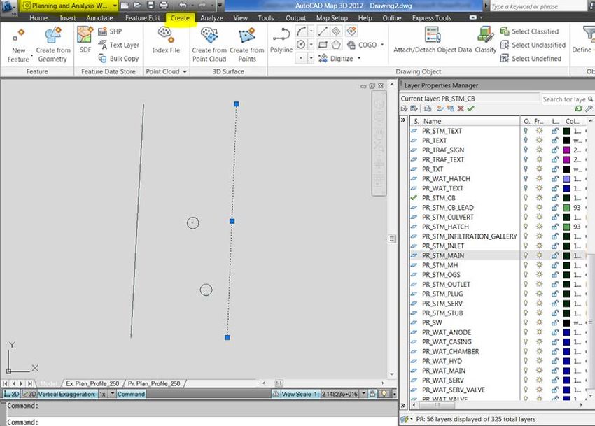
7Using Civil 3D Objects
Before you begin 1) Click on the workspace button so that you are on “Civil
intermediate steps are 3D”
2) On the Output Tab – Export Section click “Export Civil
required when using Objects to SDF”
civil 3d object data and 3) Go back to the workspace button and choose “Planning
and Analysis”
graphics. Exporting 4) On the Insert Tab click “Map Import”
these objects to an SDF 5) Double click on the SDF file you created. This will bring up
the import window.
format first allows 6) Uncheck everything except “Pipes” and “Structure”
generated data such as 7) Click on the “Data” field for pipes. A small window will
appear.
slope, and up/dn 8) Click on “Create Object Data” and hit “OK”
inverts to be carried 9) Repeat for structures. Once both are completed hit “OK”
10) Move pipes and structures to their proper layers.
over and preserve 11) Attach Object data and fill in attributes
linework.
8Use an Existing Drawing
and Attach Object Data
The “Kitchener Constructed Asset Autocad Template.dwt” file has embedded object
data that can be attached, edited and then exported to an SDF file. The main
advantage of this format is that you can mass edit similar features. By selecting
multiple features at once and attaching the object data, you can fill in several fields’
worth of data on multiple features in one action.
1. Start your drawing using
“Kitchener Constructed Asset Autocad Template.dwt”
1. Switch your workspace to a map
environment, in some versions it
is called “Planning and Analysis
Workspace (CAD)”
2. Turn off all the layers except for
the one you are working on.
3. Click on the Create tab
95. Click on the Attach/Detach Object Data 7. Once a table is selected, remove any of
button. the pre-determined data that does not
6. In the Attach/Detach Object Data window apply to the feature that it will be
select a table name from the Table drop attached to.
down to begin attaching asset * Hit enter after editing each value.
information to a drawing feature. 8. When complete click “Attach to Objects”
9. Select the features to attach data, hit enter
1010. Complete filling in the unique data OPTIONAL
for each feature, e.g. slope, invert, 12. Click the Output tab and select “As SDF”
etc. In AutoCAD Civil 3D some data is 13. Choose a name for the new SDF file
auto generated such as inverts and 14. In the export to SDF window, click load
slopes. under saved profiles, choose the
11. Save Kitchener_Template.epf. This file is a
and submit. complete export file that maps the layers
and attributes to the proper places. Click Ok.
15. Attach the new SDF file to make sure
everything exported properly.
11Exceptions –
Pumping Stations and Bridges
Pumping Stations Culverts and bridges
• Building outline polygon & Excel Form • Centreline length, show skew
• Forcemain if applicable is part of the SDF • OSIM forms page 1 and 4 only
drawing with attributes if internal diameter is 3m or greater
12Reviewing What do I check?:
The Constructed 1) Layer Walk. Anything missing?
2) Some validity check
Asset Drawing
How do I check?:
1) Layer Walk. Anything missing?
Receive and check the drawing • Home Tab -> Layers
before it is handed to the Eng. or Type “Laywalk”
Graphics Technologist: • Select a layer and hit the down
• Check for completeness arrow to quickly view each layer.
• AutoCAD Auto-Checker Potentially 31 layers.
assumes the drawing is 2) Some validity check
complete and valid • Right-Click on pipe or any
feature -> Click Properties
• In the new Properties window
review attributes such as
material, diameter, etc. 13You can also read