CLIMATIC CONTROL HC - Markus Automatik
←
→
Page content transcription
If your browser does not render page correctly, please read the page content below
CLIMATIC CONTROL HC

INSTALLATION AND USER GUIDE                                                                    GB
CLIMATIC CONTROL WITH HEAT&COOL FUNCTION ----------------------------------------------------- 3-26

GUIDE D’INSTALLATION ET D’UTILISATION                                                          F
REGULATION POUR VANNE MELANGEUSE POUR INSTALLATION CHAUFFAGE & REVERSIBLE                     27-51

MONTAGE UND BEDIENUNGSANLEITUNG                                                                D
HEIZEN- UND KÜHLEN REGLER CLIMATICCONTROL-HC                                                  52-75

                                                   1
2
GB
INSTALLATION AND OPERATION MANUAL
ClimaticControl-HC Heating & Cooling Controller
IMPORTANT!
Before starting work the installer should carefully read this Installation & Operation Manual, and make sure all i n-
structions contained therein are understood and observed.
ClimaticControl-HC should be mounted, operated and maintained by specially trained personnel only. Personnel in
the course of training are only allowed to handle the product under the supervision of an experienced fitter. Subject
to observation of the above terms, the manufacture shall assume the liability for the equipment as provided by legal
stipulations.
All instructions in this Installation & Operation manual should be observed when working with the control. Any other
application shall not comply with the regulations. The manufacturer shall not be liable in case of incompetent use of
the control. Any modifications and amendments are not allowed for safety reasons. ClimaticControl-HC mainte-
nance may be performed by service shops approved by the manufacturer only.
The functionality of the control depends on the model and equipment. This installation leaflet is part of the product
and has to be obtained.
Subject to technical modification!
Table of content
1 Application ................................................................................................................................................ 4
2 References, Symbols and Abbreviations ................................................................................................. 4
3 Safety Instructions .................................................................................................................................... 4
4 Display...................................................................................................................................................... 5
5 Installation and Electrical connections ..................................................................................................... 5
5.1 ClimaticControl-HC Installation ................................................................................................................ 5
5.2 Electrical connections............................................................................................................................... 6
5.3 Room Temperature – Direct Plug In ........................................................................................................ 7
5.3.1 Mixed circuit (Water Floor), standard room thermostat, wired type ......................................................... 7
5.3.2 Direct circuit (Panel Heater), standard room thermostat, wired type ....................................................... 7
5.3.3 Wireless room thermostat (Water Floor thermostat “trF1”) ...................................................................... 8
5.3.4 Wireless room Hygrostat (Water Floor thermostat “trF1”)........................................................................ 8
5.3.5 Wireless RF room thermostat (High temperature circuit thermostat “trF2”)............................................. 8
5.4 Wireless RF outside sensor (Inst: System parameters: Input, “OUSE”). ............................................ 9
5.5 Inputs functions (In1 & In2) ...................................................................................................................... 9
5.5.1 Input1 ....................................................................................................................................................... 9
5.5.2 Input2 ..................................................................................................................................................... 10
6 Types of operating modes / Program menu........................................................................................... 12
6.1 Types of operating modes...................................................................................................................... 12
6.2 Program Mode........................................................................................................................................ 14
6.2.1 Factory set COMFORT & REDUCED temperature times in programs P1 - P9..................................... 15
7 System Parameter Menu ....................................................................................................................... 16
7.1 System parameters setting .................................................................................................................... 16
7.2 Heating & Cooling curves....................................................................................................................... 21
7.3 Corresponding value for sensors. .......................................................................................................... 21
8 Technical Data / Materials...................................................................................................................... 21
9 TROUBLE-SHOOTING .......................................................................................................................... 22
10 Hydraulic example .................................................................................................................................. 23
10.1 Heating installation with boiler and D.H.W priority ................................................................................. 23
10.2 Installation with separate systems and 1 direction valve ....................................................................... 23
10.3 Installation with separate systems ......................................................................................................... 24
10.4 Installation with reversible Heat pump ................................................................................................... 24
10.5 Installation with reversible Heat pump ................................................................................................... 25
10.6 Complete under floor Heating and Cooling Installation.......................................................................... 25
3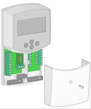
GB
1 Application
ClimaticControl-HC is developed for variable flow temperature control in heating and cooling systems particular
in low-temperature installations like floor heating and cooling systems. The flow temperature is controlled de-
pending of the outside temperature following a curve.
Using the ClimaticControl-HC the operation of a water floor system can be adapted to the actual demands of
the system. In particular, the control can be used in apartments where users have their own individual living
habits. A room temperature thermostat can also be connected. The control has a 7-day programmer including
9 factory set programs and 4 user defined programs.
The control is normally used in conjunction with a hydraulic control unit which includes circulation pumps, a
two- or three-way mixing valve and a valve actuator.
The ClimaticControl-HC has been designed for use in dry environments, e.g. in residential rooms, office spaces
and industrial facilities.
Verify that the installation complies with existing regulations before operation to ensure proper use of the instal-
lation.
2 References, Symbols and Abbreviations
For better understanding in this document references are used in the form of symbols and abbreviations, which are
described below.
Reference to further documents FlH Floor heating
Important information and application hints RaH Radiant heating (general)
Safety information or FRG Hydraulic control unit with pump and mixing
Important information about functions valve
OK-button (OK) HKV Manifold
Control button Left (◄) MuB Installation and operation manual
Control button Right (►) TB Temperature limiter
Plus button (+) UWP Circulation pump
Minus button (-) WE Boiler / heat generator
3 Safety Instructions
Before starting work disconnect power supply!
All installation and wiring work on the ClimaticControl-HC must be carried out only when de-energized.
The appliance should be connected and commissioned by qualified personnel only. Make sure to ad-
here to valid safety regulations, in particular to VDE 0100 (German standard governing power installa-
tions of nominal voltages ≤ 1000 VAC).
The ClimaticControl-HC is neither splash, nor drip-proof. Therefore, they must be mounted at a dry place.
Do not interchange the connections of the sensors and the 230V connections under any circumstances! Inter-
changing these connections may result in life endangering electrical hazards or the destruction of the appliance
and the connected sensors and other appliances.
4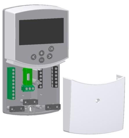
GB
4 Display
1: Operating modes
1
2: Keyboard is locked
3: Service Installation Menu
4: Manual operation / program override active 2 10
(display of temperature offset) 3 11
5: a) display temperature (°C / °F) 4
12
b) display time (12 h / 24 h) 5
6: Type of temperature displayed 6 13
a) Water temperature 7 6
b) Outside temperature 8 14
c) Room temperature (if RF room thermostat con- 9
nected)
7: Program graphic of the current day
Comfort temperature Details Pos. 6
Reduced temperature
8: Pump indicator Fig.2
9: Demand indication
Heating / Cooling / Humidity function a b c
10: Current day of the week (1 = Monday; 7 = Sunday)
11: RF reception indicator (optional).
12: a) Symbol temperature indication in °C / °F
Dimensions
b) Symbol AM / PM if 12 h mode
13: a) Outside temperature (°C / °F) 86 mm 47 mm
b) Time (12 h / 24 h)
14: Mixing valve activity indicator
Valve actuator is opening
Valve actuator is closing
OK
160, mm
Fig.3
5 Installation and Electrical connections
5.1 ClimaticControl-HC Installation
The ClimaticControl-HC can be installed directly on a solid base (e.g. a wall). For this purpose the front panel of the
ClimaticControl-HC must be removed (fig. 4a) and the back section should be fastened using appropriate screws
and pins (these are not included in the scope of supply) (fig 4b) Fix the climatic control HC on a plane surface
(wall…)
If the ClimaticControl-HC has been factory fitted with cables for connecting to a pump, valve drive, temperature
limiter, sensors etc., take care not to damage or crack the cables during the installation. Furthermore these cables
should not subjected to any tensile stress during installation. The cables will be fixed by means of the device for
strain relief at the ClimaticControl-HC.
If the ClimaticControl-HC is delivered together with a hydraulic control unit (for example FRG or FlowBox) and if it is
not attached to that unit by any installation plate or support, it should be installed next to that unit.
Pay attention to the correct connection of the cables if the ClimaticControl-HC is not installed directly on a hydraulic
control unit but at some other place for the reason of better access.
Refer to the directions about this in section 5.2 Electric connections.
5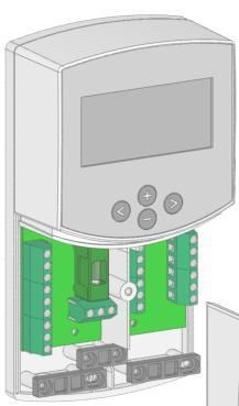
GB
OK OK OK
Strain relief
Fig. 4a Fig. 4b Fig. 4c
After making the electric connections, refit the front panel (fig. 4с).
5.2 Electrical connections
All electric connections must be made by an authorized specialist according to the local regulations on electric in-
stallations. The electrical cables must not come into contact with any hot components.
AXM117
rouge
C
Mixing circuit
COM
bleu
Pump1
blanc
O
Outside
Power Supply temperature
ARA 600
Noir 230 Vac 50Hz
C
L N N L
COM
Bleu
Marron
O
Option
Return
NR230 Water temperature.
1 Marron
C
Cold Output
N L
2 Bleu or Pump2
COM
Supplied
3 Blanc Water temperature.
O
Heating
N L
system
(Boiler…)
3 points
Vanne
Fermeture C
Commun Com
Ouverture O
Fig. 5
Optional connection – temperature limitter
TB (option) for pump1 only.
The connection is factory fitted with a cable bridge.
It must be removed if connecting TB.
6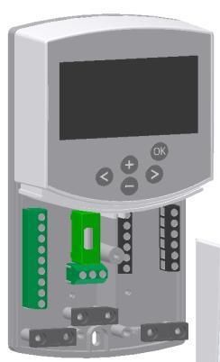
GB
5.3 Room Temperature – Direct Plug In
As an option you can plug in a room thermostat to the ClimaticControl-HC. Direct plug in of a room thermostat op-
timizes the operational time of the circulation pump and even the supply flow temperature depending on the condi-
tions in the main room.
5.3.1 Mixed circuit (Water Floor), standard room thermostat, wired type
If a wired type of a standard room thermostat is plugged in and the preset room temperature is reached in
the room, the under floor circulation pump switches off after pump delay time. (PUMP: System parame-
ters: pump delay time)
WFHT-BASIC WFHT-LCD MILUX xxx
< °C
4 4 2 1
L
2
2
N
In1 In2 4
In1 In2 4
TH Output
Fig. 6
5.3.2 Direct circuit (Panel Heater), standard room thermostat, wired type
If a second circulation pump is installed and managed by the ClimaticControl-HC (Inst: System param-
eters: installation type, “2P.x”), you can install a second wired room thermostat to manage the working of
the high temperature pump.
This pump will work in the following way: If the preset room temerature is reached in the room the High
water temperature circulation pump switches off after pump delay time. (PUMP: System parameters:
pump delay time)
WFHT-BASIC WFHT-LCD MILUX xxx
< °C
4 4 2 1
L
2
2
In1 In2 4
N
In1 In2 4
TH Output
Fig. 7
7
GB
5.3.3 Wireless room thermostat (Water Floor thermostat “trF1”)
With WFHT-RF (BASIC, LCD or MILUX)
WFHT-RF BASIC WFHT-RF LCD MILUX-RF-xxx MILUX-RF-Hygrostat
Only RF thermostats from the WFHT-RF series or the MILUX-RF series can
be used together with an active antenna 433,92 or 868MHz.
The MILUX-RF Hygrostat can be used only with the 433,92Mhz frequency
RF thermostat initialization to the Controller:
SYSTEM PARAMETERS MENU, section
RADIO-CONFIGURATION with RF room thermostat
fig.8
If a radio frequency room thermostat is plugged in, the flow temperature calculated on the basis of outdoor
temperature and the curve (= flow temperature preset value) is optimized depending on the main room tempera-
ture.
The offset value is calculated in the following way:
Adjustment = preset value of supplied temperature + (room temperature - actual value) х compen-
sation offset
(Compensation offset: System parameters: “tr1o” Flow temperature offset for “trF1”)
Example 1: preset calculated value of flow temp. = 35 °C; room temperature: preset value = 21 °C,
actual value = 19 °C; offset (tr1o) = 1,5
Estimation 1: 35 °C + (21 °C – 19 °C) × 1,5K =>> flow temperature increased by 3,0K to 38 °C
Example 2: preset value of flow temperature = 35 °C; room temperature: preset value = 21 °C,
actual value = 22 °C; offset (tr1o) = 1,5
Estimation 2: 35 °C + (21 °C – 22 °C) × 1,5K =>> flow temperature decreased by 1,5K to 33,5 °C
The pump will be switched off when room temperature will be 1°C upper the setting temperature
of the thermostat.
5.3.4 Wireless room Hygrostat (Water Floor thermostat “trF1”)
If a radio frequency room Hygrostat is plugged in, the flow temperature calculated on the basis of outdoor
temperature and the curve (= flow temperature preset value) is optimized depending on the main room
temperature. (See the previous part for more explanation)
The working mode (Heating or Cooling) of the installation could be managed by the end user directly on
the room hygrostat. (See the MILUX humidity leaflet for more explanation)
The residual humidity will be supervised by the MILUX-RF hygrostat in the house. If humidity is detected the
“Wcal“ temperature will be increased by step of 0.1°C/minute to avoid a too cold water on the hydraulic
circuit and risk of condensation in the house.
5.3.5 Wireless RF room thermostat (High temperature circuit thermostat “trF2”)
If a second circulation pump is installed and managed by the ClimaticControl-HC (Inst: System param-
eters: installation type, “2P.x”), you can install a second radio frequency room thermostat to supervise the
working of the high temperature pump.
This pump will work in the following way: If the preset room temerature is reached the High water
temperature circulation pump switches off after pump delay time. (PUMP: System parameters: pump
delay time)
Note: Only a standard room thermostat could be installed on the second circuit.
Ex: WFHT-RF (BASIC, LCD or MILUX).
8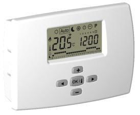
GB
5.4 Wireless RF outside sensor (Inst: System parameters: Input, “OUSE”).
As an option you can plug in a wireless RF outside sensor room thermostat to the ClimaticControl-HC. This solu-
tion is very interesting in rehabilitation, to avoid wires trough the wall, in a building management with several CC-
HC, in this case only one outside sensor can be installed to manage all the building.
WIRELESS OUTSIDE
SENSOR
The wireless outside sensor can be used only with the 433,92Mhz frequency
RF outside sensor initialization to the Controller:
SYSTEM PARAMETERS MENU, section
(Inst: System parameters: “OUSE”)
fig.9
Radio alarm: RF supervising function.
If the ClimaticControl-HC is installed with RF thermostat(s) and there is no radio signal received during more than 2
hours, a display alarm will be activated,the backlight and the small RF antenna logo radio will blink.
1. To stop the alarm, maintain the (OK) button pressed for about 10 seconds.
2. Check the batteries of the RF thermostat(s) or outside RF sensor. Please replace them if exhaust-
ed.
3. Check the position in which the antenna was installed. It must be installed in vertical position.
Installation in or on a metal body can abate the power of radio transmission. Minimize the distance
to the RF thermostat.
If radio alarm is displayed:
- Due to the wireless thermostat, the regulation will continue to work as an installation without thermostat (no com-
pensation).
- Due to the W ireless outside sensor, the regulation will continue to work with the last value received from the out-
side sensor.
5.5 Inputs functions (In1 & In2)
If no wired thermostat is installed in the house, you will have the possibility to use the two available inputs of your
ClimaticControl-HC for different functions (Inst: System parameters: Input, “In1 & In2”).
5.5.1 Input1
Inst: System parameters: Input, “HC”
You could use the input 1 to connect the an external signal which give the Heating or Coling working mode
of the installation (This signal could be done directly by a reversible input).
Inst: System parameters: Input, “Aqu”
1/ You could use the input 1 to connect the an imersion thermostat witch schould be placed in a storage
tank. In Heating mode this immersion thermostat will be use to switch off the circulation pump (Pump1) to
avoid cold water circulation in the circuit if the storage tank is discharged. (This solution is generally use
when solid wood burner is installed)
2/ You could also use this input to have a priority on domestic hot water.
In this case the pump of the heating circuit will be stopped to keep the priority on the domestic hot water.
Note:
- The heating output will stay activated even if the aquastat have stopped the circulation pump.
- To avoid problem in cooling mode, if the storage tank is filled with cold water (by heat pump...) the
aquastat function will be automatically desactivated.
9
GB
Inst: System parameters: Input, “C_b”
In case of mutizone regulation “WFHC Master RF with or without Heat&Cool function” is installed you
could use the input 1 to connect the pump relay output to swtich off the circulation pump1 in case of no
water circulation demand is asked in the house.
Note:
- The heating output will follow the circulation demand from the pump1.
5.5.2 Input2
Inst: System parameters: Input, “HC”
You could use the input 2 to connect the an external signal which give the Heating or Coling working mode
of the installation (This signal could be done directly by a reversible input).
“HC” is only available if Input1 is set on “no or Aqua”
Inst: System parameters: Input, “Aqu”
You could use the input 2 to connect the an immersion thermostat witch schould be placed in a storage
tank. In Heating mode this immersion thermostat will be use to switch off the circulation pump to avoid cold
water circulation in the circuit if the storage tank is discharged.
The immersion thermostat connected on the Input2 will manage the working of the main circula-
tion pump (Mixed circuit) if the ClimaticControl-HC drive only one pump.
In the installation with two circulations pumps, the immersion thermostat connected on the Input2
nd
will manage the working of the 2 circulation pump (direct circuit).
Note:
- The heating output will stay activated even if the aquastat have stopped the circulation pump.
- To avoid problem in cooling mode, if the storage tank is filled with cold water (by heat pump...) the
aquastat function will be automatically desactivated.
Inst: System parameters: Input, “C_b”
In case of mutizone regulation “WFHC Master RF with Heat&Cool function” is installed you could use the
input 2 to connect the pump relay output to swtich off the circulation pump in case of no circulation demand
is asked in the house.
The WFHC connecting box connected on the Input2 will manage the working of the main circula-
tion pump (Mixed circuit) if the ClimaticControl-HC drive only one pump.
In the installation with two circulations pumps, the WFHC connecting box connected on the Input2
nd
will manage the working of the 2 circulation pump (direct circuit).
Example 1: Reversible installation with circulation pump (UFH application).
In1 Used to change the working mode of the installation, signal from Heat Pump (Inst: System parameters: Input, “HC”)
In2 used to stop the pump when D.H.W is in demand (Inst: System parameters: Input, “Aqu”)
> T °C Heating &
Immersion Cooling signal
thermostat
Closed =
C 1 2 Cooling
Mode
L L’
2
In1 In2 4
Attention:
In case of the CLIMATICCONTROL-HC must be linked with the Heat pump (from the Heat /
Cool switch)
Pay attention to check the compatibility of the electrical signal before connection.
The inputs 1 or 2 (Inst: Parameter menu: In1, In2 “HC”) need a live signal “Phase L” to works
in cooling mode. Fig. 10
10GB
Example 2: Under floor heating installation with multizones connecting boxes.
In1 used to stop the pump when no heat demand is asked in the house. (Inst: Parameters menu: In1, “C_b”)
In2 used to stop the pump when the storage tank is empty (Inst: Parameters menu: In2, “Aqu”)
WFHC
Pump signal
closed = pump On
> T °C
Aquastat
(storage tank
temperature
supervising) C 1 2
2
In1 In2 4 ---------
Fig. 11
Example 2: Installation with 2 circulation pumps (Under floor heating and panel heater).
In1 used to stop the pump when the heat storage is empty (Inst: Parameters menu: In1, “Aqu”)
In2 used to stop the pump when the heat storage is empty (Inst: Parameters menu: In2, “Aqu”)
> T °C > T °C
In2 : In1: Immersion
Immersion thermostat thermostat Use to stop
Use to stop the pump2 the pump1
C 1 2 C 1 2
2
In1 In2 4
Fig. 12
11GB
6 Types of operating modes / Program menu
6.1 Types of operating modes
Selection of the operating mode is done using the arrow keys (◄) and (►). The cursor must be positioned on the
symbol of the relevant operating mode.
COMFORT mode of operation
Unlimited operation in COMFORT mode .
The system runs in constant comfort mode. The ClimaticControl-HC adjusts the flow temperature depend-
ing on the outdoor temperature and the selected curve. No temperature setback.
The display Pos. 5 shows the current flow temperature and the outside temperature at 13 (damped val-
ue). By pressing the button (OK) the preset value of flow temperature appears for about 3 seconds at 5. At
the same time the manually selectable deviation is displayed at 13 (factory setup: 00.0 = no deviation).
Using the buttons (+) or (-) you can adjust the preset value of the flow temperature. If changed, the sym-
bol appears on the display.
In heating mode of operation if no room thermostat is installed ( MuB: 5.3), the circulation pump is
running continuously. The pump switches off if the mixing 3 way valve is closed for the setting time
(PUMP: System parameters: pump delay time). That is the case when the room heating is sufficient
and the room thermostat closes all heating circuits by means of actuators. The same happens when the
value of flow temperature calculated by the ClimaticControl-HC becomes lower than the actual tempera-
ture value because of rising outdoor temperatures. If the actual value of the flow temperature falls below
the preset value, the pump will restart.
In this case to ensure a correct measure of the water temperature the pump will be start each 30min
for a short time to measure the real temperature of water inside the hydraulic circuit.
To ensure energy saving operating mode of the pump it could be switched by a “pump logic” of a elec-
tric connecting box. The connecting box is normally used together with room thermostats and electro-
thermic actuators. The “pump logic” is a potential free switching relay, the contact of which is closed
whenever higher temperature is demanded in any of the rooms. If all rooms are warm enough, the contact
opens and the pump turns off. ( MuB: 5.5)
If the heat generator / boiler (WE) is in temperature setback and the temperature supplied by the W E
is below the preset temperature calculated by the ClimaticControl-HC, heating mode is not available.
However if the circulation pump is actually running and the 2/3-way valve may also be opened by the 3-
point actuator because of room heating demand, the preset value of flow temperature may be exceeded for
a short period of time when the W E switches to heating mode. In this case, if a temperature limiter is
available, the pump might switch off and then pump operation will be possible only after the temperature
drops below the preset maximum temperature of the TB.
Trouble-shooting: The TB should be installed at a greater distance from the control unit. If necessary you
can set the TB to a higher temperature until the pump starts. After a few minutes of pump operation the
maximum allowable temperature set on the TB should be restored. Alternatively you can remove the TB
from the pipe for a while and leave the pump running for a few minutes. Then refit the TB again to the
pipe.
AUTOMATIC mode of operation
Automatic mode of operation using the built-in or user programs.
The ClimaticControl-HC is controlled according to the selected built-in or user program ( 6.2.).
The flow temperature is controlled depending on the outdoor temperature and the curve with room com-
pensation if RF thermostat is installed. ( 5.3.3 – 5.3.5).
The room compensation function will be different depending of the RF thermostat installed:
* W ith WFHTRF-BASIC or LCD (Non programmable thermostat)
The room temperature compensation will be taken in account only during Comfort period of the pro-
gram. During the Reduced period the Water temperature will follow the curve minus the temperature
setback offset.
12GB
* W ith MILUX RF (Programmable thermostat)
The room temperature compensation will be taken in account during Comfort and Reduced period
of the program. In this case the program of the MILUX RF should be the same of the water program ad-
justed on the CC-HC to have the best optimising energy consumption (the water temperature will be re-
duced due to the CC-HC program (in ) and by the setting temperature reduced also in the room due to
the MILUX RF program.
* W ith MILUX-RF HYGROSTAT (Programmable Heat and Cool thermostat with Humidity supervising)
The program will be now done on the MILUX-RF HYGROSTAT (Program made on Zone1 see the user
guide of the MILUX-RF HYGROSTAT for more explanation).
The room temperature compensation will be taken in account during Comfort and Reduced period
of the MILUX-RF HYGROSTAT program.
The Comfort and Reduced manual offsets added or subtracted to the calculated water temperature will be
always adjusted on the both working mode of the CC-HC ( 0.00°C & -10.0°C by default).
For the operation of the circulation pump please refer to the section of COMFORT mode of operation.
REDUCED TEMPERATURE mode of operation
Unlimited operation in REDUCED TEMPERATURE mode .
This is a constant mode of operation of the system. The ClimaticControl-HC adjusts the flow temperature
continuously on the basis of outdoor temperature and the selected curve and substracting the value of
temperature setback (factory setting -10.0 К in Heating mode & +3.0 К in Cooling mode).
The display indicates the current flow temperature at 5 and the outside temperature at 13. By pressing the
button (OK) the preset value for the supply flow temperature reduced by the setback in temperature is
displayed at 5 for 3 seconds. Simultaneously the reducing difference appears in 13 (without deviation =
-10.0). It can be changed by the buttons (+) or (-).
For the operation of the circulation pump please refer to the section of COMFORT mode of operation.
See the previous part for more explanation concerning the room compensation function when RF
thermostat is installed.
ABSENCE/VACATION mode of operation
Time-limited operation of REDUCED TEMPERTURE mode .
Duration can be set between 1 and 24 hours and up to a maximum of 44 days. W hen this period is ex-
pired the ClimaticControl-HC switches back to operating mode .
By means of the arrow keys (◄) the cursor is first moved to . Then appears on the display at 13.
The duration of absence can be changed using buttons (+) or (-).
Example: = 1 hour; = 1 day
Both symbols and start blinking. The remaining time is displayed at 13.
To discontinue this mode of operation before time you have to set the remaining time at 13 to using
the (-) key.
STOP mode
This mode is used to switch off the system.
The device switches off the system. The ClimaticControl-HC software version is indicated on the display
for about 3 seconds and then switches off (no indications).
By pressing any of the keys the ClimaticControl-HC can be switched on.
REMARK: W hen the ClimaticControl-HC is in STOP mode,
In Heating mode only an Anti-freeze function can restart heat relay and circulation pump to maintain the
water temperature above 10°C.
13GB
Heat & Cool Mode
Use this mode to change the working mode of your installation, Heating or cooling mode.
This mode will be only displayed if:
- The CC-HC is configured to manage a reversible installation (Inst: Parameters menu: Type, “Rev”)
- No MILUX-RF HYGROSTAT is installed ( 5.3.4) and configured to manage the Heat and Cool mode.
- No CC-HC inputs (In1 or In2) have chosen for a H_C signal input. ( 5.5)
Carfull:
IF Heat pump or other system is used and not linked with the ClimaticControl-HC, pay attention to change
the working mode on it before change on the ClimaticControl-HC. Because in this case the regulation will
not work in the correct way.
TIME AND DATE – setting
In this menu you can set the actual time and date as well as the day of the week.
Using the cursor select first and then press the (OK) key.
By keys (+) or (-) set the minutes; confirm by pressing (OK).
By keys (+) or (-) set the hour; confirm by pressing (OK)
By keys (+) or (-) set the day of the week; press (OK) to confirm.
(1 = Monday; 7 = Sunday)
6.2 Program Mode
This mode will be only displayed if no MILUX-RF Hygrostat is installed ( 5.3.4)
PROGRAM menu
In this menu you choose the program of the Controller (duration of the periods for operation in reduced
temperature and heating mode), which is to be followed in operating mode . You can choose between
factory set programs from P1 to P9 ( 6.2.1.) and one of the user’s programs from U1 to U4.
First you select with the help of the cursor. The indication appears at 5. Press the (OK) key and the
indication starts blinking. By the keys (+) or (-) now you can select the program you need and confirm it
by pressing (OK).
User-defined Programs (U1 – U4)
If you choose one of the user programs from U1 to U4, you can program the REDUCED temperature and
NORMAL heating times directly. Proceed as follows:
Day of the week.
Cursor time.
The key (+) allow you to choose a COMFORT period at the blinking cursor time.
The key (+) allow you to choose a REDUCED period at the blinking cursor time.
At 13 the time indication blinks and day 1 is highlighted, while at 7 the time cursor blinks at 0 h on the sym-
bol (heating mode). Pressing the (-) key you can move the time cursor to the symbol (REDUCED tem-
perature mode). Then the time cursor jumps to the next hour. Thus COMFORT and REDUCED tempera-
ture cycles are selected using the (+) and (-) keys.
Using arrow keys (◄) and (►) you can select the time in the same manner.
When day 1 programming is completed the time cursor switches automatically to 0:00h of day 2. Thereby
14GB
the programmed values for day 1 are stored. Programming other days is done using identical procedure
moving the cursor by pressing (►). When you switch over to programming the next day the program for the
previous day is saved. On completing the programming of the last day 7, the indication first switches to the
program menu , and in about 15 seconds back to .
If during programming no inputs are made within 20 seconds, indication switches first to the program menu
, and in another 15 seconds it returns to . The inputs were not stored.
Factory / built-in programs (P1 – P9)
If you select any of the factory programs from P1 to P9, you confirm it by pressing the key (ОК). Then
pressing the arrow key (◄) scroll back to the menu for selecting an operation mode (if the arrow key is not
pressed in about 15 seconds the display turns back to operating mode ).
6.2.1 Factory set COMFORT & REDUCED temperature times in programs P1 - P9
P1: Morning, Evening & Week-end P6: Morning, Afternoon & Week-end
P2: Morning, Midday, Evening & Week-end P7: 7h - 19h (Office)
P3: Day & Week-end P8: 8h – 19h , Saturday (Shop)
P4: Evening & Week-end P9: Week-end (Secondary House)
P5: Morning, Evening (bathroom)
The ClimaticControl-HC program operates only in mode according to the selected COMFORT and RE-
DUCED temperature periods.
15GB
7 System Parameter Menu
7.1 System parameters setting
This menu is used to set the most important parameters for the operation of the system.
To access this menu keep the (OK) key pressed for 10 seconds (in Comfort, Auto, Reduced modes).
The display shows as well as the preset curve (for example ).
Parameters are selected by pressing the (◄) or (►) keys.
To change the parameters press (ОК) and using (+) or (-) change them.
To leave the menu goes to the parameter “End” and press the (OK) key.
SYSTEM PARAMETERS
Factory Alternative User
Values Parameters description
setting setting setting
Type of installation
___ Type Following your choice the list of pa-
0
rameter will be different.
Ex: The Cooling “curve” parameter will
be not displayed if you choose “Hot”
installation.
Hot Cld, rEv
Hot
For Heating installation only
CLd
For Cooling installation only
rEv
For reversible installation
Heating parameters
Heating curve value (see fig. 7)
supplied water T° = curve(outside T°) 0.7 0.1 to 5
1
Maximum value of flow temperature in
Heating mode 45 °C (Lo+5°C) – 100 °C
2
Minimum value of flow temperature in
Heating mode 10 °C 1 – (Hi-1°C)
3
Cooling parameters
Cooling curve value (see fig. 7)
supplied water T° = curve(outside T°) 0.4 0.1 to 5
1
Maximum value of flow temperature in
Cooling mode 30 °C (Lo+5°C) – 100 °C
2
Minimum value of flow temperature in
Cooling mode 15 °C 1 – (Hi-1°C)
3
___ Inst Configuration of the hydraulic installa-
Act,
4 tion
Act: installation with actuators
The “Cold output” will manage a 3
See hydraulic
way On/Off valve to choose Heating
example
or cooling input.
section ( 10)
The “Heat output” will manage the
Boiler.
SEP: Installation with separate
system (Boiler and chillers) SEP
One output for each element will be
available.
The two following parameters are
specially made for WATTMIX regula-
16GB
tion or all others applications with 2
pumps circuits, The second pump will
nd
follow the 2 wired thermostat, and
will be wired on the “Cold output”.
2P.1: Panel Heaters + water floor 2P.1
heating and cooling system The second pump for
direct temperature
circuit (panel heater)
will be stopped in
cooling mode.
No cold water in panel
heater!
2P.2: Fan coil units and Water Floor 2P.2
Heating and Cooling system The second pump is
used to control a fan
coil circuit.
___ th Thermostat selection menu:
5
No: Installation without thermostat No, Yes, rF
No
Yes: Wired thermostat(s) is installed.
rF: Wireless RF thermostat(s) is in-
stalled.
The following parameter is only available if “th” parameter is set to “Yes”
Wired thermostat type selection:
___ thty
6
Std: Std, rEv
Std
Standard Heat only thermostat
rEv:
Reversible Heat&Cool thermostat
The following parameter is only available “th” parameter is set to “Yes” or “no” and if water sensor is mounted on
the return pipe of the hydraulic circuit.
_ _._ bGAP bGAP Boost function
7
The incoming water temperature will
be increased by +20%* if the return
temperature is less than calculated
water temperature minus bGAP set-
ting.
Wret < Wcal – bGAP => WCal +20%*
5.0°C 1 to 20°C
Press on the (OK) to view the instan-
taneous value of the return sensor.
Remark: if no water return sensor is
wired then this boost function is
bypassed.
*Remark2: in Cold mode “-20%”
The following parameter is only available if “th” parameter is set to “rF”
___ trF1 RADIO-CONFIGURATION with RF thermostat for room temperature (trF1)
8
1. Press the (OK) key. Using the (+) or (-) keys to set the Controller into rf init mode.
„INI thrF“ appears on the display.
2. Set the RF thermostat into rf init mode ( MuB).
3. If successful rf initialisation the RF thermostat sends a radio signal to the Controller.
The actual value of room temperature appears flashing on the display instead of ”INI”.
4. The process is completed by pressing the (OK) key of the Controller.
5. Exit the rf init mode of the RF thermostat. ( MuB).
Selecting „no thrF“ disconnects the RF thermostat from the Controller and discontinues
the room temperature plug-in function respectively.
17GB
Connection of wireless room thermostat is only possible using appropriate device.
The following parameter is only available if “th” parameter is set to “rF”
and if “inst” parameter is set to “2P.1” or “2P.2” (2 pumps mode)
___ trF2 RADIO-CONFIGURATION with RF thermostat for WATTMIX system (trF2)
9
(2 pumps system with panel heaters or fan coils)
same radio configuration sequence as parameter “trF1” just above
The following parameter is only available if “th” parameter is set to “rF”
Flow temperature offset for RF thermostat
___ tr1o for room temperature (trF1)
10
3.0°C 0.1 to 9.9C
See the working explanation ( 5.3.3).
___ in1 Wired Input1 selection: ( 5.5.1).
11 th1
un-adjustable
th1: the wired room thermostat should be
wired on Input1 because “th” parameter is set no, Aqu,
to “YES”) HC or C_b
no: Input1 not used (nothing wired) no
Aqu:
A water Aquastat contact is wired on Input1.
If over temperature is reached (contact open)
then Pump1 circulator is stopped and the
mixing valve is closed.
HC:
A Heat/Cool switching signal is wired on In-
put1 to manage the working mode of the in- The HC signal
stallation. (contact between point 2 and In1 or could be done by a
phase signal on In1) heat pump.
Check the electri-
Heating = no signal (open circuit ) cal compatibility
Cooling = Phase signal (closed circuit) before connection
C_b:
A pump signal from a connecting box is wired
on Input1 to manage the working of the
pump1.
(contact between point 2 and In1 or phase
signal on In1)
Pump ON = Phase signal (closed circuit)
Pump OFF = no signal (open circuit )
___ in2 Wired Input2 selection: ( 5.5.2).
12
th2
not-adjustable
th2: the wired thermostat for second pump
system should be wired on
Input2 (because “th” parameter is set to “YES”
and “inst” is set to “2P.x”)
no, Aqu,
no HC or C_b
no: Input2 not used (nothing wired)
Aqu:
A water Aquastat is wired on Input2.
If over temperature is reached (contact open)
then:
- if “inst”=”Act or SEP”, Pump1 circulation is
stopped & mixing valve is closed.
- if “inst”=”2P.x”, direct circuit Pump2 circula-
18GB
tion is stopped.
HC:
A Heat/Cool switching signal is wired on In-
put1 to manage the working mode of the in-
stallation. (contact between point 2 and In1 or The HC signal
could be done by a
phase signal on In1) heat pump.
Heating = no signal (open circuit ) Check the electri-
Cooling = Phase signal (closed circuit). cal compatibility
before connection
C_b:
A pump signal from a connecting box is wired
on Input1 to manage the working of the
pump1.
(contact between point 2 and In1 or phase
signal on In1)
Heating = no signal (open circuit )
Cooling = Phase signal (closed circuit).
- if “inst”=”Act or SEP”, water floor Pump1
circulation is stopped & mixing valve is closed.
- if “inst”=”2P.x”, direct circuit Pump2 circula-
tion is stopped.
___ OUSE Outside sensor menu:
13 Yes: Wired outside sensor is installed.
No: Installation without outside sensor
The regulation will work like a “thermostat” Yes No, rF
with a adjustable “Wcal” temperature injected
on the circuit.
rF: Wireless RF outside sensor is installed.
The following parameter is only available if no outside sensor is installed and the “OUSE” parameter is set to “no”.
Outside temperature:
___ OU t This menu is used to fix the outside tempera-
14
ture to have the desired calculated water
temperature in accordance to the curves.
Example: -49.0°C to
00.0°C
Ou t = 0°C, Curv = 1 50.0°C
Wcal => 40°C
You could adjust with more accuracy the
“Wcal” temperature since the main screen
with the “Comfort” and “Reduced” offset.
The following parameter is only available if “OUSE” parameter is set to “rF”
RADIO-CONFIGURATION with RF sensor for outdoor temperature
14 Same radio configuration sequence as parameter 8 “trF1” above.
Temperature indication in °C or °F °C °F
16
Time indication mode
24H 12H Am/Pm
24 hours or 12 hours
17
Side-track protection
YES (ac-
NO (inactive)
18 tive)
When YES is selected the pump and the auxiliary actuator are activated at midday 12 hrs, if they
haven’t been active for a period of 24 hours. (12h00: Pump ON 1min, 12h01: Open actuator 2min,
12:03: Close actuator 2min)
19GB
The following parameter “Pump” is only used when no RF thermostats are installed and if no inputs (In1 & In2)
are used for connecting box (C_b) and aquastat (Aqu) function.
Pump delay time:
Time duration to switch off the pump 030
after the stop demand from the 001 to 060,
For best use
wired thermostat or after complete and above “- - -“
the duration
_ _ _ PUMP close of the 3 way mixing valve.
should be =>
= infinite delay, the
19
This function is also interesting to pump will be ON all
2xPWM cycle
avoid permanent ON/OFF cycle of the time
of the thermo-
the pump when “PW M” thermostat is
stat
installed.
Manual mode (or test function) for valve drive respectively 2/3-way valve
20
By pressing the (+) key the valve drive opens. The display shows “OPEN“ and .
By pressing the (–) key the valve drive closes. The display shows “CLOSE“ and .
By pressing the (◄) or (►) key current position of the valve drive is kept. Displays “STOP“
There is a actuator security anti-short delay: when switching from “OPEN“ to “CLOSE“
or “CLOSE“ to “OPEN“, the actuator will be stopped during 15s
Floor / screed preheating
program. 0 dry 7 dry
The program is started by selecting „7 dry“ and runs automatically.
___ PrH
21
For a period of 3 days the flow temperature is kept at 25 °C (days 7, 6, 5). For next 4 days the flow
temperature is maintained at its preset maximum value (days 4, 3, 2, 1).
The number of the days until the end of the heating program is displayed.
Floor / screed dehumidifi- 0 PrH 7 to 60 days
cation program Default value after “ON”
=> 13 Days
The program is started by selecting the desired numbers of days and runs automatically.
Example: 13 days selected: (3days rise + 7days at Hi + 3days decrease)
22 For a period of 3 days the flow temperature will be increased up to the “Hi” value, then the tempera-
ture will be kept at the “Hi” value during 7 days. For the last 3 days the temperature will be decreased
up to the “Lo” value.
Example2: 7 days selected: (3days rise + 1day at Hi + 3days decrease)
The number of the days left until the end of the fllor dehumidification program is displayed.
Reset function
By keeping the (OK) key pressed for about 5 seconds all system parameters, time and day
23 of the week as well as user programs in are reset to the factory setting. Established
radio configuration to rf thermostats, if any, is also erased. The cursor moves to .
End Press on the (OK) key to exit the installer menu and come back to the main menu in
24 mode.
20GB
7.2 Heating & Cooling curves
Outside temperature (°C)
Fig. 9
7.3 Corresponding value for sensors.
To be checked with an ohmmeter with sensor unplugged.
Temperature (°C) Resistance value (Ohm) Temperature (°C) Resistance value (Ohm)
-20°C ~94 k 40°C ~5,3 k
-10°C ~54 k 50°C ~3,6 k
0°C ~32 k 60°C ~2,5 k
10°C ~20 k 70°C ~1,8 k
20°C ~12,5 k 80°C ~1,3 k
30°C ~8 k
8 Technical Data / Materials
Measured temperature accuracy: 0,1 °C
Operating temperature: 0 - 50 °C
Flow temperature control range: 0 - 100 °C
Regulation characteristics: Non-linear logarithmic PID control
Intelligent 3-point control (automatic detection of operating point)
Electrical protection: Class II – IP 30
Supply voltage: 230 V (±10%), 50 Hz
Outputs: pump: 5 A / 250 V relay (L, N, PE)
Cold: 5 A / 250 V relay (L, N, PE)
Heat: 5 A / 250 V relay (L, N, PE)
3-point control: 2 TRIACS => 75 W max.
Sensors: outside temperature: CTN 10 K at 25 °C (class II, IP55)
supplied temperature: CTN 10 K at 25 °C (class I, IP68, no coupling)
return temperature: CTN 10 K at 25 °C (class I, IP68, no supply)
Software version: _. (displayed when switched off – STOP mode).
21GB
9 TROUBLE-SHOOTING
X. TROUBLE
X.X Possible reason Elimination
1. The display shows
1.1 at 13 Check whether the connection of sensor cable is correct.
Disconnected outside temperature sensor Check the cable for damages.
Replace the cable or the sensor, if necessary.
1.2 at 5 Check whether the connection of sensor cable is correct.
Disconnected flow temperature sensor Check the cable for damages.
Replace the cable or the sensor, if necessary..
2. Incorrect flow temperature
2.1 Incorrect flow setting temperature Check if no offset are adjusted ( 6.1).
The displayed calculated temperature is not in COMFORT and REDUCED temperature Offset.
accordance with the regulation curve.
2.2 Too high flow temperature due to incorrectly con- Check the connection of the valve drive ( 5.2).
nected valve drive (reverse action)
2.3 Too low flow temperature due to incorrectly con- Check the connection of the valve drive ( 5.2).
nected valve drive (reverse action)
2.4 Incorrect selected operation mode Select the correct mode of operation.
2.5 When ClimaticControl-HC operating in AUTO- - Check the factory program or the user program settings
MATIC mode: and pay attention to the correct setting of COMFORT and
- incorrect programming of built-in or user pro- REDUCED temperature periods of operation.
gram
- incorrect setting of time / day of the week - Check the setting of the time / day of the week.
3. The pumps or the valve drive does not work
3.1 Cable connections reversed. Check the electric connections ( 5.2).
3.2 Pump connected to temperature limiter. - Check the electric connection ( 5.2).
- Check the maximum temperature setting of the TB.
- Check the ambient temperature of the TB. If necessary,
change its position.
- Check the TB operation. Replace it if necessary.
Remark:
Lock function
To prevent mistakes after installation, all critical parameters are not accessible any more after 4 hours power on. If
you want to modify these parameters, you must unplug and plug in controller. No settings are lost when unplug-
ging, or after a power failure.
After 4 hours you can still change all the other parameters to optimize your system.
22GB
10 Hydraulic example
10.1 Heating installation with boiler and D.H.W priority
(1 Water floor heating zone)
*Option RF Parameter menu
- Room temperature compensation Inst AcT
Th rF
In1 Aqu D.H.W. priority
Security Contact thermostat
Optionnal Return sensor (Used when no RF thermostat is installed)
Supply water sensor
Main pump
AF Mixing 3 way valve
M
M
Boiler control
Aquastat
D.H.W.
1
10.2 Installation with separate systems and 1 direction valve
(1 reversible W ater floor zone)
- Room temperature compensation Parameter menu
*Option RF
- Humidity Inst Act
Th rF
Security Contact thermostat
Optionnal Return sensor (Used when no RF thermostat is installed)
Supply water sensor
Main pump
AF Mixing 3 way valve
M
M
Boiler control
1 2
M
3 way valve signal (On in cooling mode)
23GB
10.3 Installation with separate systems
(1 reversible W ater floor zone)
*Option RF - Room temperature compensation Parameter menu
- Humidity Inst SEP
Th rF
Security Contact thermostat
Optionnal Return sensor (Used when no RF thermostat is installed)
Supply water sensor
Main pump
AF Mixing 3 way valve
M
M
Boiler control Water chillers signal
1 2
10.4 Installation with reversible Heat pump
(1 reversible W ater floor zone and 1 panel heater circuit)
Parameter menu
- Room temperature - Room temperature compensation Inst 2P.1
- Humidity Th rF
In1 HC
In2 Aqu
Security Contact thermostat
Supply water sensor
AF
Pannel heater WFH Main pump1
pump
Mixing 3 way valve
M
M
Aquastat
HeatPump
signal
HP
1
24GB
10.5 Installation with reversible Heat pump
(1 reversible W ater floor zone and 1 Fan coil circuit)
Parameter menu
- Room temperature
- Room temperature compensation Inst 2P.2
- Humidity Th rF
In1 Aqu
In2 Aqu
Security Contact thermostat
Supply water sensor
AF
Pannel heater WFH Main pump1
pump
Mixing 3 way valve
M
M
HeatPump Aquastat
signal
HP ST
1 Aquastat
10.6 Complete under floor Heating and Cooling Installation
(UFH Multizone)
Parameter menu
RF Master Heat&Cool Inst Act when H.P
Inst SEP
Pump signal
Th rF
A
In1 Aqu when H.P
AF
TB
B RT1 RT2 RT3
A+B
A A A
Main room hygrostat to
manage the heat&cool
change over of the installa-
tion and program for all the
house.
M
M
M
Aquastat
ST HP
1 2
Separate systems or Reversible heat pump
25GB 26
F
GUIDE D’INSTALLATION ET D’UTILISATION
ClimaticControl-HC contrôleur de chauffage et de climatisation
IMPORTANT!
Avant de commencer les travaux, le monteur doit lire, comprendre et observer les présentes instructions de
montage et de service.
Seul un spécialiste en la matière est autorisé à effectuer le montage, le réglage et la maintenance du ClimaticCon-
trol-HC. Un monteur en formation ne peut réaliser de travaux sur l'appareil que sous la surveillance d'un expert. La
responsabilité du fabricant conformément aux dispositions légales s'applique uniquement dans le cas du respect
des conditions précitées.
Veuillez observer l'ensemble des instructions de montage et de service lors de l'utilisation du ClimaticControl-HC.
Toute utilisation autre n'est pas conforme. Le fabricant ne répond pas des dommages occasionnés par une
utilisation abusive du ClimaticControl-HC. Pour des raisons de sécurité, aucune transformation ou modification
n'est admise. Seuls les ateliers de réparation désignés par le fabricant sont habilités à réparer le ClimaticControl-
HC.
Le contenu de la livraison de l'appareil varie selon le modèle et l'équipement. Cette notice d’installation fait partie
intégrante du produit et doit être conserver.
Sous réserve de modifications techniques !
Table des Matières
1 Application .............................................................................................................................................. 28
2 Références, Symboles and Abréviations ............................................................................................... 28
3 Consignes de sécurité............................................................................................................................ 28
4 Afficheur ................................................................................................................................................. 29
5 Installation et raccordement électrique .................................................................................................. 29
5.1 Installation du ClimaticControl-HC ......................................................................................................... 29
5.2 Raccordements électriques.................................................................................................................... 30
5.3 Thermostat D’ambiance – Direct Plug In ............................................................................................... 31
5.3.1 Zone plancher « In1 » : température d’eau variable thermostat de type filaire...................................... 31
5.3.2 Zone radiateurs « In2 »: consigne de température d’eau fixe (Sans vanne mélangeuse) .................... 31
5.3.3 Circuit à vanne mélangeuse, thermostat d’ambiance RF “trF1” ............................................................ 32
5.3.4 Circuit à vanne mélangeuse, thermostat hygrostat d’ambiance RF “trF1” ............................................ 32
5.3.5 Circuit direct (sans vanne mélangeuse), thermostat d’ambiance RF “trF2” .......................................... 32
5.4 Wireless RF outside sensor (Inst: System parameters: Input, “OUSE”). .......................................... 33
5.5 Fonctions des entrées logique (In1 & In2) ............................................................................................. 33
5.5.1 Entrée 1 “In1” ............................................................................................................................. ............ 33
5.5.2 Entrée 2 “In2” ......................................................................................................................................... 34
6 Description des modes de fonctionnements .......................................................................................... 36
6.1 Types de fonctionnement ....................................................................................................................... 36
6.2 Menus de programmation ...................................................................................................................... 38
6.2.1 Description des programmes usine P1 à P9 .......................................................................................... 40
7 Menu Installation et Annexes ................................................................................................................. 41
7.1 Paramètres d’installation ........................................................................................................................ 41
7.2 Courbe de régulation .............................................................................................................................. 46
7.3 Valeurs de référence ohmique pour les sondes de température. .......................................................... 46
8 Caractéristiques Techniques.................................................................................................................. 46
9 DEFAUTS ET SOLUTIONS ................................................................................................................... 47
10 Example d’installation hydraulique ......................................................................................................... 48
10.1 Installation chauffage avec Chaudière et gestion priorité E.C.S ............................................................ 48
10.2 Installation avec P.A.C réversible ou élément séparés (avec 1 vanne de direction) ............................. 48
10.3 Installation avec élément séparés .......................................................................................................... 49
10.4 Installation avec P.A.C réversible .......................................................................................................... 49
10.5 Installation avec P.A.C réversible .......................................................................................................... 50
10.6 Installation avec P.A.C réversible ou élément séparés.......................................................................... 50
27You can also read