Closed-loop Hybrid

  Tesla Turbine
←
→
Page content transcription
If your browser does not render page correctly, please read the page content below
Closed-loop Hybrid Tesla Turbine
Warnings – read before use
It is important to understand that this turbine is an experimental device. It is not intended
to be used for prolonged periods or to be permanently used. If you do use the turbine for
this function, use at your own risk.
Make sure that all the screws are tightened before use
Make sure the grub screws on the generator coupling are particularly tight as they
will be spinning at high speed.
Always use eye protection/goggles when using the turbine.
It is recommended that the RPM is monitored when running under no/little load.
This can be achieved by using a multi-meter with a Hz option.
After longer periods of use or possible stress check the bearings for damage or wear.
The bearings have a ‘slide on’ fitting making them easy to remove/replace/change;
however this means it is possible that the bearing will spin in the housing at very
high speeds or over longer running times. This would cause damage to the housing
after prolonged use. If you intend to run the turbine for longer periods or high speed
it is recommended the bearings are sealed (a special glue) using a bearing sealant.
Do not touch the bulbs while running they will be very HOT
Do not touch the motor or shaft while running
Do not touch or put anything close to the electrics, board or bulb holder while
running. The underside of the bulb holders (board) is electrified while in use.
Although at only a low voltage.
Under extreme pressures and stress Tesla stated that disks are liable to warp. It is
unlikely to happen on this version but please be aware that it is possible.
The turbine is designed for use with compressed air but with steam, water and hot
gases in mind. Proceed at your own risk.Specification
Sizes
Turbine diameter: 100mm
Turbine length
120.75mm
(including generator):
Blade/disk diameter: 78mm
Blade/disk thickness: 1.2mm
Blade/disk gap: 1.5mm
Number of Blades/disks: 5
Over base size: 180mm x 110mm
Materials Used
Case : 6082 aluminium
Spindle : 303 stainless steel
Disk Spacers : 6082 aluminium
Injector : CZ121 brass
Connectors
Inlet : 1/4 BSP (British Standard Pipe)
Outlet : 1/4 BSP (British Standard Pipe)
Adapters (supplied) : Uni connector
Generator
type : 3 phase AC
MAX Output : 150 watts
Interesting features
Reversible: Yes, using flat screwdriver
Design improvements: Injector system and modular designs
Replaceable parts: Motor can be upgraded
Bulbs can be changed or removed
Possible experiments: New design for injector
new disks, amount of disks
different mediums
different generators
Free spare: free 'blank' injector that can be redesigned
Medium: Compressed air, vacuum.
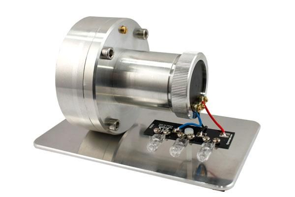
Steam, hot gasses such as R134a or even water.New Tesla Metal Turbine – Closed Loop, Hybrid, Ceramic Bearings and Higher Efficiency Once again this Tesla turbine is eagerly awaited. Further improvements have been made after plenty of R&D from the last turbine. The turbine efficiency has been increased by increasing nozzle pressures and added shaped spacers that act like an impulse turbine AFTER the useful energy has be captured using the discs. This may not be that satisfactory to some Tesla purists that don’t think that impulse turbine technology should be mixed with the Tesla turbine but it does increase performance and they can be removed if required and replaced with your own spacers/washers. There is plenty of interest in using Tesla turbines with organic rankine cycle systems, to enable power generation with waste heat or solar power. A number of major changes have been made to make this turbine useable in a closed-loop system (working fluid is constantly reheated and cooled ). In the other words no air, gas, steam, water can escape. It is now sealed ready for use in pressured system. It has been tested at 150psi using air. The turbine still has a standard a 1/4" BSP threaded connector for both the inlet and outlet pipes. A 1/4" BSP to Universal (uni) adapter is provided to allow easy connection to an air compressor (5+ SCFM recommended). The turbine comes with a 3 phase generator and 3 x 20 watt bulbs so that a load can be drawn, this generates 60 watts. The generator can produce up to 150watts leaving plenty of headroom for experimentation. The turbine design and generator mount allows for possibility of changing the generator or connecting to something else. The turbine is supplied on a aluminium base for display and demonstration purposes (connected using two M6 Hex cap screws). History of Tesla Turbines A Tesla turbine is a quite unique technology. It was invented and patented by Nikola Tesla on the 21st October 1909 at the United States Patent Office from experiments done in England. The US patent 1061206 was granted on the 6th May 1913, although historical documents suggest that that Tesla first showed a 200 horsepower (about 150kw) 16,000 RPM version on the 10th of July 1906 (on Tesla’s 50th birthday). From what Tesla wrote in the patent it seems his experiments were mainly done with fluids but had confirmed it works with air as well. Tesla had his own personal requirements for a generator for his laboratory. You have to remember use of electrical power was still in its infancy which Tesla played a critical role developing many of the electrical components we now take for granted. Typically Tesla found his alternative and better way of generating power, using a steam boiler powering a tesla turbine which in turn powered an AC generator. Unlike conventional turbines, jet engines and most pumps, Tesla’s turbine can be designed to be reversible with no loss in efficiency. Normally compressed air, fluids or steam is applied to the inlet and the turbine spins giving a mechanic rotational output. However, it can also double up as a pump, by rotating the shaft the air/fluid/steam can and be sucked and blown from the inlets / outlets. This makes it unique in being a reversible turbine and a reversible pump. However efficiency increases can be made by tailoring the pump to the medium. In other words an air powered turbine may have some slight design changes compared to water powered turbine.
Sadly unlike the work done with electricity the Tesla turbine never became popular and was simply
forgotten about. Only in the last few years has there been new interest.
Tesla turbines are also known as cohesion turbines, bladeless turbines, boundary layer turbines and
Prandtl layer turbines.
Working with Air, Steam, Water, Vacuum and Hot Gases
This turbine is ideal for experiments with air, steam, water and hot gases. With air or a Vacuum no
special precautions need to be undertaken. With hot gases ensure the generator housing (and hence
generator) does not over heat; prolonging the generator life. Try to keep the temperatures below
100C. I would suggest trying heat sinks and cooling-jackets around the generator casing. With steam
and water mount the turbine so the generator is vertical and facing upwards (at the top). This means
if any water does get into the generator compartment it can return back into the main compartment
and outlet over time. If this is still a persistent problem I would suggest changing the bearings for
ones with rubber seals (bearings 625-2RS) which will provide extra protection to the generator.
With steam and water slowly increase the pressures with each experiment and check the generator
housing. The turbine has been tested at 150psi with compressed air. If you do use high pressures
please understand the risks and take the appropriate safety precautions.
Key points
Closed loop - ideal for organic rankine cycle systems
Hybrid Turbine - using Tesla technology and impulse turbine technology to improve
efficiency
Ceramic Bearings - faster, more efficient, high temperatures
Higher Efficiency
Runs from air, a vacuum, steam, gases and even waterHow to take apart
1. Firstly remove the wires connected to the turbine by removing the nuts.
2. Then remove the second nut under each wire. This frees up the electrical connectors
3. There is knurled ring/part on the turbine (same end as electrical connectors). Undo this but try
to keep the connectors (and black disk) from spinning round.
4. Slide the knurled ring off, carefully remove the black disk.
5. The metal tube around/over the generator simply unscrews. Grip by hand and unscrew.
BTW: Be careful when replacing it as the thread is fine and needs to be perfectly
align otherwise you will rip the thread. The generator is now exposed.
6. Unscrew the four small bolts close around the motor.
7. Now unscrew the grub screw on the brass connector (the brass connector connects the turbine
to the motor).
8. The generator will slide off.
9. Unscrew the 4 bolts on casing.
10. Carefully slide the front casing off.
11. The rotor and disks will be held in one side of the casing. Carefully remove it.
How to put back together
1. When putting back together this MUST do in correct order to get perfect alignment. The turbine
will have extra resistance or cease if not done correctly.
2. Lightly slide the rotor/disks into the back casing. Make sure the bearings are correctly seated.
3. Slide the front casing on to the back casing. Make sure the shaft/rotor comes through ok. Make
sure there is no dust on the parts where the two casing parts meet. This will ensure a good seal.
4. Check the rotor/disks spin freely.
5. Hand tighten the four bolts to keep the casing together. Now tighten with moderate pressure
only. Now tighten with a torque wrench, working in a star-shape pattern until all of the bolts are
completely tightened.
6. Prepare to attach the generator to the casing. Hold the generator in your hand. Put the bolts and
brass on ready.
7. Align the shaft to the brass connector. Note that the shaft has a flat, align this with the grub
screw on the brass shaft connector. LIGHTLY push on. DON’T tighten the grub screw yet. Leave it
lose.
8. Align all the bolts to the threaded holes on the casing and hand tighten.
9. Now tighten the four bolts working in a star-shape pattern until all of the bolts are completely
tightened.
10. Tighten the grub very slightly on the brass connector (this ensures the shaft is aligned)
11. Spin the generator to make sure it spins freely (it sound spin for a second or two). If it does not
spin freely undo everything and repeat.
12. Provided it now spins freely tighten the grub screw quite hard.
13. Screw on the tube to the casing. Make sure it is PERFECTLY aligned. But the casing flat on a table
to double check. Screw on slowly to make sure it is not cross threaded.
14. Put the connectors through the black plastic disk.
15. Put on the knurled ring and tighten by hand.
16. Put on a nut on each connector and tighten them. The connector will probably spin so use pliers
to hold.
17. Put on the wires and the second nut on each connectorThe generator and converting the 3 phase AC to DC output A 3 phase generator was chosen because of the cost, performance, efficiency, size and ability to run at high speed over its DC equivalents. The generator is an ‘outrunner’, with static coils/windings are in the centre and the magnets rotating around. This allows it to run at very high speeds. The generator is capable of generating around 150watts. The turbine is supplied with 3 x 20 watt lamps to add some load, but these could be increased or even decreased for lower wattage versions. If the bulbs are removed the generator will free- wheel with almost no resistance. Typically the generator will produce 1volt for every 1400rpm. Hence The turbine needs to run at 16,800rpm for 12 volts. Three bulbs were the easiest way to place a load on the generator for demonstration purposes. However a 3 phase output is not ideal in most cases for a practical output, this can easy be fixed using a bridge rectifier or otherwise known as a diode rectifier. This will create a pulsed DC output, which can be smoothed using capacitors if required. The circuit required is as follows. For further information on the subject visit http://en.wikipedia.org/wiki/Bridge_rectifier Generator Specification Max Power 150 Watts Max RPM (manufacturer suggestion) 20,000rpm Diameter 27.8mm(1.092”) Length 28.9mm (1.14”) Shaft Diameter 4.0mm (.1575”) Mounting Screw Thread 2.5mm, max depth 4.5mm, on 16mm (.625”) bolt circle Max Case Temperature 65 C (149F) Efficient Operating Current 5-13Aamps How to contact us If you have any further questions you may contact Glenn at sales@gyroscope.com or visit www.gyroscope.com
You can also read