COBRA Description Counter Battery Radar - Hensoldt
←
→
Page content transcription
If your browser does not render page correctly, please read the page content below
COBRA
Counter Battery Radar
Description
Content                                                                 Figures
COBRA Description .............................................. 1      Figure 1 – Cobra Configuration.......................... 2
1         Scope ................................................. 1     Figure 2 – COBRA Radar System Vehicle (RSV)
2         Applicable Documents ..................... 1                              Major Subassemblies........................... 2
3         Description ........................................ 1        Figure 3 – Range Modes ...................................... 3
3.1       Major Component List ......................... 1              Figure 4 – COBRA Coverage Diagram.................. 4
3.2       Operational Concept ........................... 3             Figure 5 – Location of Batteries............................ 7
3.2.1     COBRA Missions ................................. 3            Figure 6 – Hostile Battery Location Reports.......... 9
3.2.2     COBRA Coverag ................................. 3             Figure 7 – Adjustment / Registration Mission........ 9
3.2.2.1   Range Modes ...................................... 3          Figure 8 – Adjustment / Registration Report ....... 10
3.2.2.2   Electronic Scan .................................... 3
3.2.2.3   Mechanical Antenna Adjustment ......... 4
3.2.3     Operating Modes ................................. 5
3.2.3.1   Automatic and Autonomous Operation .5
3.2.4     COBRA Deployment ............................ 5
3.2.4.1   Crew .................................................... 5
3.2.4.2   Encamp/Decamp ................................ 5
3.2.4.3   Background Maps ............................... 5
3.2.4.4   Determination of COBRA Position and ...
          Antenna Orientation ............................. 5
3.2.4.4.1 Inertial Navigation Unit ......................... 5
3.2.4.4.2 Backup alignment ................................ 5
3.2.4.5   Adjustment of Search Pattern to
          Terrain Mask ........................................ 6
3.2.4.5.1 Use of Terrain Map .............................. 6
3.2.4.5.2 Terrain Mask minimum range ............... 6
3.2.5     Priorities .............................................. 6
3.2.5.1   Mission Priority .................................... 6
3.2.5.2   Location Zone Priority .......................... 6
3.2.5.2.1 Location zones .................................... 6
3.2.5.2.2 Use of Location Zone Priority ............... 7
3.2.5.2.3 Zone shapes and numbers .................. 7
3.2.5.3   Weapon system class priority .............. 7
3.2.6     Location of Batteries ............................ 7
3.2.6.1   Battery Location Criteria ...................... 7
3.2.6.2   Location Rate ..................................... 7
3.2.6.3   Location Rate Modes .......................... 8
3.2.6.3.1 Normal Location Rate Mode ................ 8
3.2.6.3.2 High Location Rate Mode .................... 8
3.2.6.4   Height Correction in Location Mission .... 8
3.2.6.4.1 Automatic Height Correction ................ 8
3.2.6.4.2 Interactive Height Correction ................ 8
3.2.6.5   Hostile Battery Location Reports ......... 9
3.2.7     Adjustment /
          Registration of Friendly Fire .................. 9
3.2.7.1   Adjustment / Registration Mission ........ 9
3.2.7.2   Adjustment / Registration
          Mission Operation .............................. 10
3.2.7.3   Adjustment /
          Registration Mission Report ............... 10
3.2.8     ECM Status ....................................... 10
3.2.8.1   ECM Status Monitoring ...................... 10
3.2.8.2   Location of Jammers ......................... 10
3.2.9     Transportability .................................. 10
4         Glossary ........................................... 11
5         Cobra Characteristics .................... 12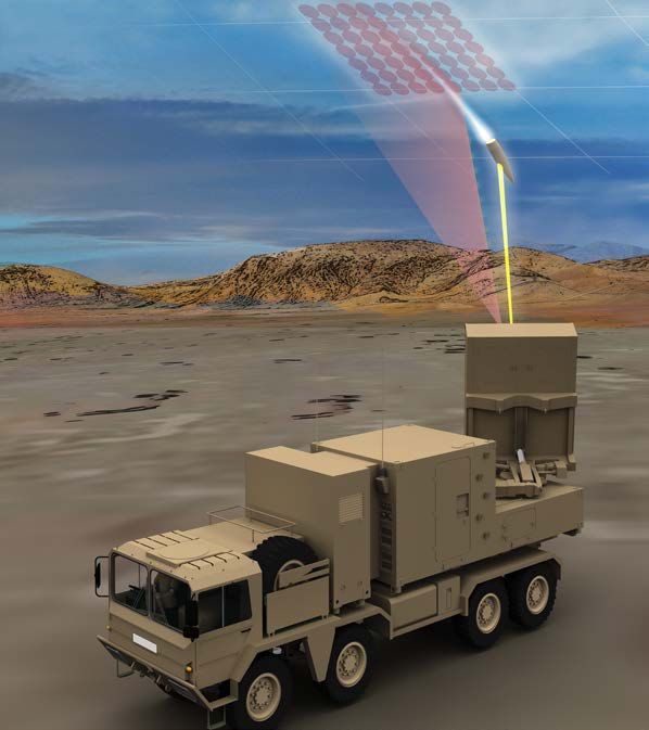
COBRA Description
1 Scope
This description provides a summary of the performance, design and manufacture requirements
for the Radar System Vehicle (RSV) of COBRA.
2 Applicable Documents
The design, manufacture and test activities conducted during the development and production
of COBRA were performed in accordance with applicable standards. Information regarding the
standards applied, and the extent to which they are applicable can be obtained from the manu-
facturers, EURO-ART.
3 Description
COBRA is the Radar System for the accurate and rapid location of enemy guns, rocket launchers,
and mortars. It may also be used for the Adjustment/Registration of the fire of own artillery.
COBRA is fielded on a single vehicle, and achieves its full performance requirements without
levelling or stabilisation jacks thereby exceeding rapid deployment and high mobility requirements.
Powerful software algorithms automatically compensate for terrain slopes (COBRA pitch and roll)
and calculate each search beam elevation to graze the radar horizon before transmission begins.
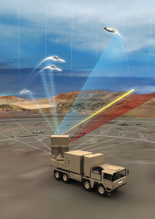
3.1 Major Component List
The COBRA Configuration and Major Sub-Assemblies of the COBRA RSV are presented in Figure
1 and Figure 2.
The COBRA RSV consists of:
• Radar Module Set (RMS)
– Contains all equipment required for artillery location and registration operation, for communi-
cation with the User and for field radio communications
- NBC and shell-fragment protected
- Integrated Inertial Navigation Unit allows autonomous navigation and orientation plus
compensation for wind and shell blast
• Modified Carrier Vehicle (MCV)
– Medium cross-country capability
– Vehicle Modification Set to facilitate mechanical and electrical integration with RMS
• Prime Power Unit (PPU)
– Mounted on Carrier Vehicle with RMS
– Provides all AC and DC Power required for COBRA Operations
• C3 Equipment (Supplied by Purchaser)
1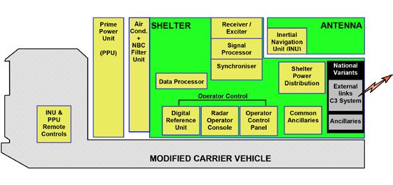
S)
                                                                 )
                                                                U

                                                                                  RM
                                                              PP

                                                                                t(
                                                            t(

                                                                              Se
                                                          ni
                                      V)

                                                         U

                                                                              e
                                     C

                                                       er

                                                                            ul
                                   (M

                                                                          od
                                                      w
                                                    Po
                                   le

                                                                         M
                                 ic

                                                                          r
                                                    e
                               eh

                                                                        da
                                                  im
                             rV

                                                                      Ra
                                                Pr
                          rie
                        ar
                       C
                       ed
                    ifi
                  od
                 M

    Figure 1 – Cobra Configuration

    Figure 2 – COBRA Radar System Vehicle (RSV) Major Subassemblies

2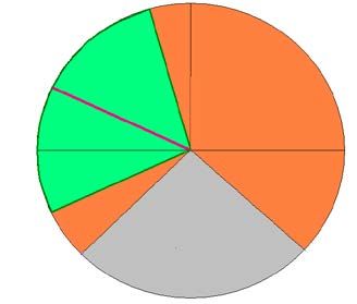
3.2 Operational Concept
In its primary role, COBRA:
▪ provides intelligence on enemy artillery, including:
▫ location of hostile battery position co-ordinates and width-and-orientation of
3.2 battery front, Concept
Operational
▫ classification
In its primaryof enemy
role, COBRA:artillery (into guns, rocket launchers, or mortars),
▫ location of the impact areas co-ordinates of enemy fire,
▪ conducts•Adjustment/Registration
provides intelligence on enemy of artillery,
Friendly Fire
including:
– location of hostile
▫ location of fall of shot battery position co-ordinates and width-and-orientation of battery front,
– classification
▫ fire correction parametersof enemy artillery (into guns, rocket launchers, or mortars),
– location of the impact areas co-ordinates of enemy fire,
▪ determines jamming data.
• conducts Adjustment/Registration of Friendly Fire
▫ Azimuth and elevation
– location of main-lobe jammers with jamming analysis data
of fall of shot
▫ Presence of side-lobe jammers
– fire correction parameters
• determines jamming data.
3.2.1 COBRA Missions
– Azimuth and elevation of main-lobe jammers with jamming analysis data
Hostile Battery Location
– Presence Missions can
of side-lobe be conducted against:
jammers
▪ Guns and mortars
▪ 3.2.1
Multiple COBRAlaunchers
rocket Missions
Hostile Battery
Whilst continuing to track and Location
locateMissions can be conducted
new enemy batteries,against:
COBRA can conduct
Registration/Adjustment of Friendly Fire missions to correct Friendly Battery’s Counter-Fire
• Guns and mortars
COBRA achieves the above capabilities by tracking ballistic projectiles, and extrapolating the
• Multiple rocket launchers
observed part of the
Whilst continuingtrajectories to the
to track andground.
locate new enemy batteries, COBRA can conduct Registration/
3.2.2 Adjustment
COBRA Coverage of Friendly Fire missions to correct Friendly Battery’s Counter-Fire COBRA achieves
the above capabilities by tracking ballistic projectiles, and extrapolating the observed part of the
The maximum trajectories
COBRA Coverage from a radiation position is detailed in
to the ground.
Figure 4
3.2.2 COBRA Coverage
3.2.2.1 The maximum COBRA Coverage from a radiation position is detailed in Figure 4
Range Modes
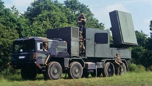
COBRA detects
3.2.2.1 and tracks
Range Modes enemy artillery
firings. COBRA detects and tracks enemy
Total coverageartillery
is achieved
firings. using 3
instrumented
range modes:is achieved using 3 instru-
Total coverage
▪ Standardmented
instrumented range mode: 30
range modes:
km
▪ • Standard instrumented
Short instrumented range mode:
range mode: 20
30 km
km • Short instrumented range mode:
▪ Long instrumented
20 km range mode: 40
km • Long instrumented range mode:
40 km
All three
modes
Allcan
threebe usedcan
modes during a single
be used during a
mission. single mission. Coverage: PZ = Priority Zone
The maximum computation of battery
The maximum computation of battery locations
locations and display capability is instru- Figure 3 – Range Modes
and display capability is instrumented to 50 km.
mented to 50 km.
Figure 3 – Range Modes
3.2.2.2 Electronic Scan
COBRA electronically scans the tasked azimuth sector each side of the surveillance direction.
Detection and location characteristics can be improved in certain directions by reducing the
electronically
3.2.2.2 Electronic Scanscanned sector to any sector width down to 5°.
COBRA electronically scans the tasked azimuth sector each side of the surveillance
direction. Detection and location characteristics can be improved in certain directions by
reducing the electronically scanned sector to any sector width down to 5°.
EURO-ART INTERNATIONAL PROPRIETARY INFORMATION Page 3
3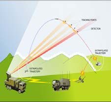
In case of the reduced azimuth sector scan, projectiles leaving the surveillance sector
    continue
    	Intocase  be tracked   until completed
                    of the reduced             tracks
                                    azimuth sector scan,are recorded.
                                                         projectiles leaving the surveillance sector continue
               to be tracked until completed tracks are recorded.
    3.2.2.3 Mechanical Antenna Adjustment
    3.2.2.3 Mechanical Antenna Adjustment
    The  COBRA antenna can be mechanically rotated in azimuth by ± 90 degrees with respect to
    	The COBRA antenna can be mechanically rotated in azimuth by ± 90 degrees with respect to
    the longitudinal  axis ofaxis
             the longitudinal  theofvehicle andand
                                     the vehicle in elevation
                                                     in elevationfrom  –5°toto++35°
                                                                  from –5°       35°relative
                                                                                      relative
                                                                                             to ato a plane
                                                                                                  plane perpen-
    perpendicular   to  the shelter  bottom   surface
             dicular to the shelter bottom surface .    .

                                                         Antenna normal

                                    Detection
                                   Range 40Km

                                                                            270º
        Mechanical                                                                                 Mechanical
         limit left                                                                                limit right

                                                              COBRA
                                                              vehicle

    Figure 4 – COBRA Coverage Diagram
        Surveillance sector                       Antenna electronic scan ±45º from surveillance direction
       Surveillance sector          Antenna electronic scan ±45º from surveillance direction
                                                  Antenna mechanical slew limits ±90º from vehicle normal
        Available coverage                      results
                                    Antenna mechanical      in 270º
                                                       slew limits       available
                                                                   ±90º from            coverage
                                                                             vehicle normal
        Available coverage
                                    results in 270º available coverage

        Display Coverage            Computation of locations instrumented to 50Km
           Display Coverage                       Computation of locations instrumented to 50Km

    Figure 4 - COBRA Coverage Diagram

4                  EURO-ART INTERNATIONAL PROPRIETARY INFORMATION                                                Page 4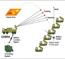
3.2.3     Operating Modes

3.2.3.1 Automatic and Autonomous Operation
	In the Automatic mode of operation, the User transmits control commands to COBRA and
        receives mission results via the C3 data link.

	In the Autonomous mode, the COBRA Operator enters or modifies the mission parameters. If
  a C3 equipment failure occurs whilst COBRA is in the Automatic mode COBRA switches to the
  Autonomous mode.

3.2.4     COBRA Deployment

3.2.4.1   Crew
          The automation inherent in the COBRA design allows the crew size to be minimised:

  • Driver
  • Radar Operator
  • C3 Operator
	The above roles can be performed by one, two or three soldiers. The built-in test facilities
  detect and locate faults to a single LRU in most cases. Operational Status is reported via the C3
  System. This allows one Maintainer to monitor the status and react to failures of several COBRA.

3.2.4.2 Encamp/Decamp
	COBRA can be brought into action in less than 15 minutes. The encamp time includes the time
        taken to load the Digital Terrain Map (DTM) from hard disk, and to complete COBRA Initialisation
        and mission parameter definition. It is possible to come out of action within 5 minutes.

3.2.4.3 Background Maps
	Digital Maps provided by the User Army are loaded onto COBRA for a battlefield day. An
        800 km2 map is loaded from CDs. When COBRA is initialised for a mission a 100 km2 map is
        displayed with COBRA at its centre. Mission data is superimposed on the map as soon as it is
        acquired.

3.2.4.4   Determination of COBRA Position and Antenna Orientation

3.2.4.4.1 Inertial Navigation Unit
	The integrated Inertial Navigation Unit provides navigation data (COBRA position X,Y,Z) and also
          measures the instantaneous antenna orientation. This allows for automatic antenna mechanical
          positioning, and compensation for terrain slopes and unexpected movements (wind or shell blast
          effects)

	A Vehicle Motion Sensor (VMS) is attached to the carrier vehicle to provide the INU with vehicular
  movement data.

3.2.4.4.2 Backup alignment
	As an emergency mode, it is possible to determine the angle orientation of the antenna me-
          chanical boresight and antenna plane by means of external equipment such as a (PFE) and to
          introduce this data as a substitute for missing INU angle information.

                                                                                                           5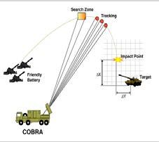
3.2.4.5 Adjustment of Search Pattern to Terrain Mask
    	For every mission, COBRA automatically adjusts the elevation of its search pattern to the terrain
            mask.

    3.2.4.5.1 Use of Terrain Map
    	The initial adjustment is calculated from the Digital Terrain Map (DTM) terrain altitude data,
              without radiation, prior to active operation. At the beginning of radiation the mission, COBRA
              adjusts each search beam to the optimum position. In the absence of Terrain Altitude Data for
              the COBRA deployment area, the User can measure the elevation of the radar horizon using
              an external device such as a theodolite (provided as PFE), and input this data via the Operator
              Console, or allow COBRA to measure the crests of the radar horizon using a radiation method.

    3.2.4.5.2 Terrain Mask minimum range
    	When positioned for a mission, if COBRA detects a potential obstacle which prevents optimum
              location performance, the relevant blind sector will be displayed to the Operator on the graphics
              display.

    3.2.5 Priorities
    	Three types of prioritisation can be applied to COBRA mission data

              • Mission Priority
              • Location Zone Priority
              • Weapon system class priority

    3.2.5.1 Mission Priority
    	Mission priority is applied to allow COBRA to react to possible mission conflicts that prevent the
            completion of simultaneous missions.
            The default mission priority order, from the higher to lower priority, is:

      • Location of hostile batteries,
      • Adjustment/Registration of friendly fire.
    	This order may be modified during mission definition. COBRA responds to these priorities, in the
      event of a mission conflict, by reducing system resources for the mission of lower priority. Where
      necessary, this may include the mechanical slew of the antenna to accommodate the higher
      priority mission prior to active transmission.

    3.2.5.2   Location Zone Priority

    3.2.5.2.1 Location zones
    	Using battlefield intelligence data, the COBRA Operator or the User has the facility to define
              location zones, which represent areas where hostile batteries are positioned or their potential
              targets (impact zones) to which priorities can be assigned. For this purpose, 6 levels of priority
              are defined; the lowest level is used to exclude (censor) zones. To allow rapid reference to the
              defined zones, an Area ID can be assigned via the C3 link. If Area IDs are assigned, they are
              included in the appropriate Location Reports.

6
3.2.5.2.2 Use of Location Zone Priority
In extremely high density firing scenarios, COBRA responds to location zone priorities, in the
event of approaching saturation, by reducing search and track coverage in lower priority zones,
starting with the zone of lowest priority.
In order that appropriate Friendly Fire responses may be tasked, the Hostile Battery Reports to
the User indicates the Location Zone Priority.
3.2.5.2.3 Zone shapes and numbers
A total of 5 Location Zones may be defined. The outline of Hostile Battery Location Zones may
be sectors, circles, triangles, quadrangles, pentagons, hexagons or the remaining complementa-
ry area within COBRA coverage sector.
Up to 4 location zones of hostile impacts may be defined. They can be circular or grid oriented
rectangles.
3.2.5.3 Weapon system class priority
The COBRA Operator or the User (via C3) is able to assign priorities to the three weapon system
classes of guns, rocket launchers, and mortars. For this purpose, 4 levels of priority are defined;
the lowest level is used to exclude weapon system classes. The weapon systems class priorities
are used in conjunction with the location and impact zone priorities to set up filter criteria for the
reports to C3.
3.2.6 Location of Batteries
3.2.6.1 Battery Location Criteria
For COBRA all trajectory origins within
a circle (of “correlation radius”), firing
at the same target (similar velocity),
are assumed to belong to one battery.
A battery location is considered to be
complete if during a predetermined time
(“correlation period”) the number of simi-
lar trajectory origins within the correlation
circle equals a certain threshold the
“correlation number”.
Batteries not fulfilling the correlation crite-
ria are reported to the COBRA Operator
and the C3 System as “Incomplete
Batteries”.
Correlation radius, correlation number,
Figure 5 – Location of Batteries
and correlation period may be adjustable
by the COBRA Operator or the User.
3.2.6.2 Location Rate
In a High Density Engagement, COBRA can locate more than 40 Batteries in 2 minutes and
conduct Friendly Fire Correction Missions simultaneously.
73.2.6.3 Location Rate Modes
To enable COBRA to automatically adapt to fluctuating target densities, COBRA provides two
Location Rate Modes:
• Normal Location Rate Mode
• High Location Rate Mode
The Operator must authorise the use of High Location Rate Mode, otherwise COBRA will always
apply Normal Location Rate Mode.
3.2.6.3.1 Normal Location Rate Mode
This mode is characterised by the following:
• Constant target track length in order to maximise battery location and impact point location
accuracy,
• Battery location procedures and criteria can be defined by the Operator or the User.
• Battery width and orientation of battery front will be estimated (unless the battery comprises
only one track),
• Tracks of all types (swarms and/or salvos and/or singles) are correlated to form batteries,
• Impact point will be estimated.
3.2.6.3.2 High Location Rate Mode
In very high density battlefield scenarios, conditions may evolve in which detection probability
for new projectiles is reduced due to the time and energy expended in tracking already detected
projectiles. The High Location Rate Mode allows the User to maintain the detection rate and
Location Accuracy of new targets by optimisation of the Location Mission Parameters.
3.2.6.4 Height Correction in Location Mission
Height corrections for Hostile Battery Locations will be performed automatically or interactively.
3.2.6.4.1 Automatic Height Correction
COBRA uses the terrain altitude data to calculate the height of each located battery. The trajec-
tory of the tracked projectile is propagated back to the point at which it intersects with the terrain
height.
3.2.6.4.2 Interactive Height Correction
In the absence of a Digital Terrain Map, the COBRA Operator can request an Interactive Height
Correction procedure to correct the height of either single batteries or groups of batteries.
83.2.6.5 Hostile Battery Location Reports
The location report contains the following
information:
• Battery identification (ID)
• Co-ordinates of battery centroids or
single location
• Area ID of battery centre
• Height of battery centre
• Number of shells or indicator of salvo
• Estimated CEP of location error
• Time of location
• Priority
• Weapon system class
• Impact point centroid co-ordinates and
area identifier
• Width and orientation of battery front
• Indicator for incomplete battery Figure 6 – Hostile Battery Location Reports
• location (if applicable)
3.2.7
Adjustment / Registration of Friendly
Fire
COBRA is capable of correcting Friendly
Fire either as a separate Mission or
Simultaneously with a Hostile Battery
location Mission
3.2.7.1 Adjustment / Registration Mission
An Adjustment / Registration mission
may include a fire sequence of several
shells, fired with the same parameters.
The sequence may be fired in one or in
several mission activations.
The required parameter set to be
provided by C3, or to be entered by the
Operator, for such a mission must at Figure 7 – Adjustment / Registration Mission
least include:
• Firing ID
• Type: Registration, Individual Adjustment, Mean Adjustment
• Start Criterion
– Time over Target (TOT) or
– User (via C3) or
– Operator.
• Co-ordinates of firing position centre /altitude
• Target ID
• Co-ordinates of target centre including altitude.
93.2.7.2
Adjustment / Registration Mission
Operation
COBRA computes the impact points
of friendly fire by first determining the
required search volume which must be
positioned to provide sufficient track
time for accurate impact point location.
Search beams are then scheduled to
scan the search sector. When the projec-
tile passes through the search sector it is
detected, verified, and tracked as closely
as possible to the terrain mask. The
trajectory is extrapolated beyond that
mask to the plane defined by the target
altitude contained in the mission set up
data.
3.2.7.3
Adjustment / Registration Mission Figure 6 – Hostile Battery Location Reports
Report
The following data is recorded in the
mission data file, is transmitted to the
User via the C3 link and displayed to the COBRA Operator, either at the alphanumeric or graphic
terminal, at his discretion:
• Firing identification (ID),
• Co-ordinates of target centre,
• Altitude of the target centre,
• For each projectile the co-ordinates of the impact point,
• Impact point deviations,
• Time of first observation,
• Mean point of impact data of all projectiles or a selected subset of projectiles.
• Confidence of impact point co-ordinates.
3.2.8 ECM Status
COBRA checks for the interference caused by jamming, assesses the impact of the interference
and takes appropriate action
3.2.8.1 ECM Status Monitoring
When COBRA detects the presence of ECM interference, the Operator is warned by acoustic
and visual alerts.
3.2.8.2 Location of Jammers
During passive non-transmitting periods, COBRA provides azimuth and elevation direction for
jammers within the passive observation search sector using the antenna mainlobe; in addition,
information on jamming mode, jamming strength, presence of mainlobe or sidelobe jamming,
and jammed frequency channels is gathered and stored.
During radar transmissions a second means of gathering information on non-responsive and
responsive and moving jammer platforms is provided.
3.2.9 Transportability
COBRA is transportable by air, sea and rail.
104 Glossary
AC Alternating Current
C3 Command, Control and Communications
COBRA Counter Battery Radar
DC Direct Current
DTM Digital Terrain Map
ECM Electronic Counter-Measures
INU Inertial Navigation Unit
MCV Modified Carrier Vehicle
NBC Nuclear, Biological Contamination
NEMP Nuclear Electro-Magnetic Pulse
PFE Purchaser Furnished Equipment
PPU Prime Power Unit
RMS Radar Module Set
RSV Radar System Vehicle
TOT Time Over Target
115 COBRA Characteristics
COBRA Configuration (See 3.1)
Single vehicle, no levelling or stabilisation required
Operator cabin complete with Operator and C3 Consoles
On-board Prime Power Unit
On-board, User Artillery Integrated Command and Control System
On-board Inertial Navigation System (Laser Gyro) with GPS option
Air-conditioner with NBC filtration (Gas, Chemicals and Particles)
Shelter protected against shell fragments and small arms fire
COBRA Missions (See 3.2.1)
Hostile Battery Location:
Location of Battery Centre / Battery width and Orientation /
Weapon Classification / Impact Area / Weapon and Area Priority
Friendly Fire Registration and Adjustment:
Location of fall of shot / Adjustment parameters
Range Modes (See 3.2.2.1)
Short / Standard / Long 20, 30, 40 Km
Coverage 1200 Km2
Operating Modes
Automatic – missions directed and results transmitted via C3 link
Autonomous – no connection with C3 link, Operator defines
missions
COBRA Deployment (See 3.2.4)
Crew size 1–3 soldiers
Encamp time 5–15 minutes
Decamp time 3–5 minutes
Use of on-board Inertial Navigation System
Background Digital Maps and Digital Terrain Maps (DTM)
Computation of Terrain Mask from DTM
Priorities (See 3.2.5)
Mission Priority
Location Zone Priority
Weapon System Class Priority
Location of Batteries See (3.2.6)
Battery Location Criteria
Number of Weapons 1–8
Correlation Radius 100–200m
12Correlation Time 10–999secs
Location Rate >40 batteries in 2minutes
Location Rate Modes Normal, High
Adjustment/Registration of Friendly Fire (See 3.2.7 )
Adjustment mission simultaneously with Location Mission
Accuracy 15Km – 0.35% range
Transportability (See 3.2.9)
By air, sea and rail (or using a suitable spare flat-bed vehicle)
EURO-ART INTERNATIONAL PROPRIETARY INFORMATION Page 13
Additional Data
Shelter size 600x250x210 cm
Prime Power Unit Size 80x250x200 cm
Vehicle platform (Interface Frame) dimensions 750x250 cm
Vehicle Payload 10 tons
Shelter weight Approx 8000
Prime Power Unit Weight 1900 Kg
13COBRA – We know
where they are.
Subject to change without notice.
MediaServices 0406
0115
Company Profile
EURO-ART International The EURO-ART consortium was formed in 1989 by the predecessor
EWIV companies of Thales Air Systems SA, France, Thales UK Ltd, EADS,
Leopoldstr. 242 Germany and Lockheed Martin, USA, to undertake development and
80807 Munchen, Germany production of the COBRA System for the French, UK and German
Phone: +49 (89) 350 64 0 Governments which has resulted in the delivery of 29 COBRA Systems.
Fax: +49 (89) 350 29 800 In August 2007, EURO-ART International EWIV (“EURO-ART Inter
office@euroart.cc national”), an European Economic Interest Group based in Germany,
www.euroart.cc was established between Thales Air Systems SA and EADS, as the
enterprise responsible for all future marketing and sales of the COBRA
System to new customers.You can also read