Coding with Squishy Circuits - Shopify
←
→
Page content transcription
If your browser does not render page correctly, please read the page content below
Coding with Squishy Circuits

                    © 2017 - 2018 – Squishy Circuits Store, LLC
                             Last revised August 2018

Comments, Questions, Concerns? Please reach out at: ContactUs@SquishyCircuits.com
Table of Contents
       Introduction .................................................................................................................................................. 2
          Coding with Squishy Circuits? ................................................................................................................. 2
          Learning Objectives................................................................................................................................... 2
          Educator Preparation Material ................................................................................................................. 2
       Background Knowledge ................................................................................................................................ 3
          Electricity and Ohms Law .......................................................................................................................... 3
          Arduino ..................................................................................................................................................... 4
          Voltage Dividers ........................................................................................................................................ 4
          Breadboards .............................................................................................................................................. 5
       Project 1: Squishy Sound............................................................................................................................... 6
          Summary and Background Knowledge ..................................................................................................... 6
          Materials: .................................................................................................................................................. 6
          Schematic: ................................................................................................................................................. 6
          Figure: ....................................................................................................................................................... 6
          Code: ......................................................................................................................................................... 7
       Project 2: Squishy RGB LED Controller .......................................................................................................... 8
          Summary and Background Knowledge: .................................................................................................... 8
          Materials: .................................................................................................................................................. 8
          Schematic: ................................................................................................................................................. 8
          Figure: ....................................................................................................................................................... 9
          Code: ....................................................................................................................................................... 10

www.SquishyCircuits.com                                                                                                                                                       Page 1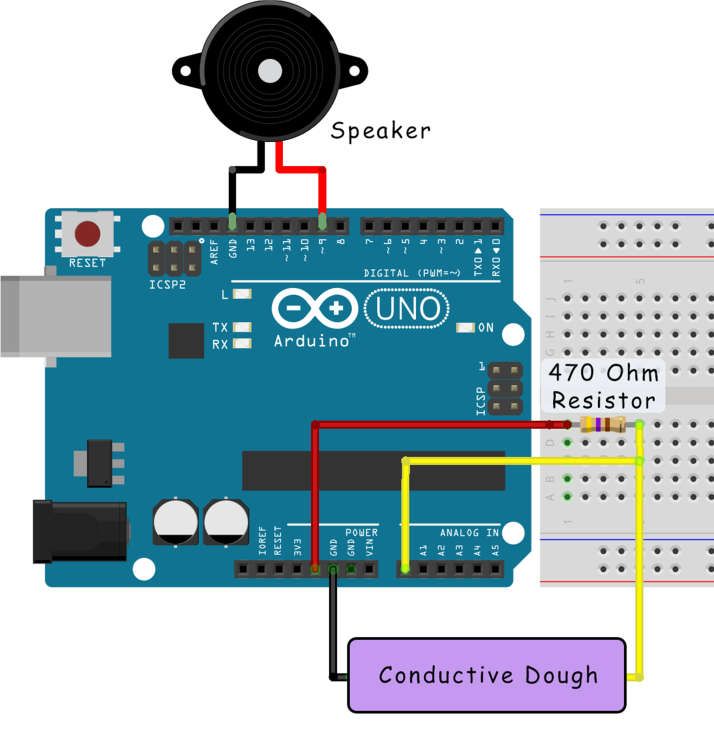
Introduction
       Coding with Squishy Circuits?
       In these projects we use an
       Arduino (device similar to a small
       computer) to measure the
       resistance of conductive dough.
       When we change the shape of the
       dough the resistance also changes.
       For example, making the dough a
       longer, thinner “pipe” for the
       electricity to flow, increases the
       resistance. We can then cause an
       output to change based on the
       resistance.

       Note: This project is more
       advanced. We include some
       background information but if you
       would like more information about something or are confused, we encourage you to research more
       about that particular topic or to contact us.

       Learning Objectives
          1.   Students will be able to explain how resistance, voltage, and current are related.
          2.   Students will explore how resistance is based on physical shape.
          3.   Students will design and build a circuit to accomplish a desired outcome.
          4.   Students will be able to modify and implement code on their microprocessors.

       Educator Preparation Material
       Supplies needed for each student or group of students:
         o    Computer with Arduino Software
         o    Arduino Uno Board (or similar)
         o    Conductive Dough
         o    Speaker
         o    LEDs
         o    Breadboard
         o    470 Ohm Resistors (or close)
         o    Wire

www.SquishyCircuits.com                                                                                 Page 2
Background Knowledge
       Electricity and Ohms Law
       Electricity is the flow of charge called electrons. When describing electrical circuits, three terms are used
       – voltage, current, and resistance.

       Voltage relates to how much potential there is between the positive and negative ends. It is measured
       in volts.

       Current is a measurement of how many electrons are moving through a conductor. It is measured in
       amps.

       Resistance is how difficult it is for the electricity to flow through the conductor. It is measure in ohms.

                                                It can be difficult to visualize these concepts. So, a more tangible
                                                example is to think of water instead of electrons. Think of a
                                                water tower – it holds water high up in the air, which gives the
                                                water a potential. This is like voltage.

                                                Imagine there are two pipes going from the top of the water
                                                tower to the ground - one that was big and one that is small. If
                                                you had to fill up a bucket with water, would you put the bucket
                                                under the big pipe or the small one? You would choose the big
                                                pipe because it would fill much faster. This is like the current,
                                                similar to the amount of water flowing.

                                                If you’d measure the amount of water going through the pipes,
                                                you’d notice that there is less water flowing through the smaller
                                                pipe than the big one. It is harder to push water down a smaller
                                                pipe than a large one. This is like resistance – the bigger the pipe,
                                                the less resistance.

       In electricity, these three concepts work the same way but instead of pipes and flowing water, we have
       conductors carrying electrical current. The three principles are related by Ohms Law:

                                             ( )=               ( )∗                 ( )
                                Which can also be written as:        =                =

       The water analogy still works with Ohms law – basically the higher the water height (higher voltage) and
       the bigger the pipe (less resistance), the more water flows down the pipe (higher current).

www.SquishyCircuits.com                                                                                                 Page 3
Arduino®
       From the Arduino website, “Arduino is an open-source electronics platform based on easy-to-use
       hardware and software. Arduino boards are able to read inputs - light on a sensor, a finger on a button,
       or a Twitter message - and turn it into an output - activating a motor, turning on an LED, publishing
       something online. You can tell your board what to do by sending a set of instructions to the
       microcontroller on the board.”

                                                 Image credit: Arduino

       We have chosen to write this guide for Arduino boards because they are popular, inexpensive, easy to
       use, and have many educator resources. If you are completely unfamiliar, we suggest viewing the
       Arduino website, www.arduino.cc, which has guides/tutorials and the software required to program
       your Arduino board.

       Arduino boards contain a microprocessor (essentially a small computer) and a host of useful prototyping
       tools. Using the Arduino software, instructions, called code, are written and programmed to the Arduino
       board.

       Voltage Dividers
       Arduinos have analog inputs which measure voltage. If we were to provide 5 volts on one side of the
       dough and connect the other side to ground, there would always be 5 volts going through the dough.
       This really does not do anything useful.

       But, if we put another resistor in the same circuit, now we can measure the voltage at the point in-
       between the resistor and the dough. As the dough’s resistance changes, more or less of the voltage will
       be present at that point because the 5 volts is split proportionately between the two resistances. This is
       called a voltage divider and is a fundamental circuit for engineers.

www.SquishyCircuits.com                                                                                             Page 4
The equation that describes a voltage divider is:      =        ∗

                                 For these projects, we know that:
                                 R1 = 470 ohms
                                 Vin = 5 volts
                                 and Vout is measured by the Arduino’s analog input.

       By performing some algebra, we can then rearrange the equation to find the resistance of the
                                     ∗
       conductive dough:     =              =

       Breadboards
       Breadboards are extremely useful prototyping tools because they allow you to quickly and easily
       connect multiple electrical components together. They are arranged in a grid with each column of 5
       connected to each other. There are also two power rails, blue for ground and red for positive. There are
       two sides of a breadboard and they are separated from each other. In the image below, the
       connections are shown with lines connecting the squares. When using breadboards, resistors, wires, and
       other components are inserted into each of the squares.

                             .

www.SquishyCircuits.com                                                                                           Page 5
Project 1: Squishy Sound
Summary and Background Knowledge
The most popular example of a Squishy Circuits
microprocessor project is Squishy Sound. Squishy Sound uses
the conductive dough to change the pitch of a speaker – the
higher the resistance, the higher the pitch.
Materials:
o Computer with Arduino Software
o Arduino Uno Board (or similar)
o Conductive Dough
o Speaker (the piezoelectric buzzer sold on our website
does NOT work for Squishy Sound)
o Breadboard
o 470 Ohm Resistors (or close)
o Wire
Schematic:
+5V from Arduino
470 Ohm Resistor Speaker
Figure:
From Digital I/O 9 on Arduino
To Analog In 0 on Arduino
To Ground on Arduino
Conductive Dough
Ground on Arduino
www.SquishyCircuits.com Page 6Image created with Fritzing
Code:
//Squishy Sound - Code written by Sam Johnson and Modified by Matthew Schmidtbauer for the Squishy
Circuits Project
//Port Definitions and Variable Declarations:
#define SpeakerOutput 9
int analog = 0; // Common resistor connected to analog pin 0 outside leads to ground and +5V
int raw = 0; // Variable to store the raw input value
int frequency = 0; // Variable to store Frequency
void setup()
{}
void loop()
{
raw = analogRead(analog); // Read Voltage over Dough
frequency = raw*2; // Calculate Frequency
tone(SpeakerOutput,frequency); // Output Frequency to Sounding Device
}
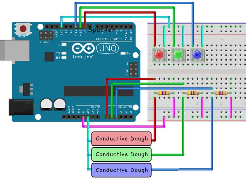
www.SquishyCircuits.com Page 7Project 2: Squishy RGB LED Controller
Summary and Background Knowledge:
In this project, we will use three different voltage divider
circuits to control the brightness of three different LEDs. The
color of the LEDs do not matter, but we have chosen to use a
red, green, and blue LED which are the primary colors of light.
Using them, we can make any color depending on the
brightness of each color. This is similar to a pixel on your TV or
cell phone which work the same way, but are so small your
eyes cannot see the individual colors. The light has to mix
together to create different colors so putting it through a
semi-translucent obeject will help mix the colors (wax paper
works well). All colors mixed together make white!
Materials:
o Computer with Arduino Software
o Arduino Uno Board (or similar)
o Conductive Dough
o 3 LEDs
o Breadboard
o 3 - 470 Ohm Resistors (or close)
o Wire
Schematic:
: :
+5V from Arduino
From Digital I/O 9, 10, 11 on Arduino
470 Ohm Resistor LED in Red,
Green, or
To Analog In 0, 1, 2 on Arduino Blue
Conductive Dough To Ground on Arduino
Ground on Arduino
www.SquishyCircuits.com Page 8Figure:
Image created with Fritzing
www.SquishyCircuits.com Page 9Code:
//Squishy RGB LED Controller
//Port Definitions and Variable Declarations:
#define RED_LED 9
#define GREEN_LED 10
#define BLUE_LED 11
int analog_RED = 0; // common resistor connected to analog pin 0 outside leads to ground and +5V
int raw_RED = 0; // variable to store the raw input value
int BRIGHTNESS_RED = 0; //Variable to store Brightness Value (0-255)
int analog_GREEN = 1; // common resistor connected to analog pin 1 // outside leads to ground and +5V
int raw_GREEN = 0; // variable to store the raw input value
int BRIGHTNESS_GREEN = 0; //Variable to store Brightness Value (0-255)
int analog_BLUE = 2; // common resistor connected to analog pin 2 // outside leads to ground and +5V
int raw_BLUE = 0; // variable to store the raw input value
int BRIGHTNESS_BLUE = 0; //Variable to store Brightness Value (0-255)
void setup()
{
pinMode(RED_LED, OUTPUT);
pinMode(GREEN_LED, OUTPUT);
pinMode(BLUE_LED, OUTPUT);
}
void loop()
{
//Read Voltages over Dough:
raw_RED = analogRead(analog_RED);
raw_GREEN = analogRead(analog_GREEN);
raw_BLUE = analogRead(analog_BLUE);
//Generate Brightness Value (PWM Values = 0-255) from Raw Voltages (0- 1023)
if(raw_RED =500) {BRIGHTNESS_RED=0;}
else {BRIGHTNESS_RED=-.7286*raw_RED+364.45;}
analogWrite(RED_LED, BRIGHTNESS_RED); //Output PWM Value to Light
if(raw_GREEN =500) {BRIGHTNESS_GREEN=0;}
else {BRIGHTNESS_GREEN=-.7286*raw_GREEN+364.45;}
analogWrite(GREEN_LED, BRIGHTNESS_GREEN); //Output PWM Value to Light
if(raw_BLUE =500) {BRIGHTNESS_BLUE=0;}
else {BRIGHTNESS_BLUE=-.7286*raw_BLUE+364.45;}
analogWrite(BLUE_LED, BRIGHTNESS_BLUE); //Output PWM Value to Light
}
www.SquishyCircuits.com Page 10You can also read