COMMUTER CATEGORY CONVERSION INSTRUCTIONS FOR CONTINUED AIRWORTHINESS - Super King Air 200 Series - ICA Manual No. 006-30 Revision 3 December 2019
←
→
Page content transcription
If your browser does not render page correctly, please read the page content below

Waco Regional Airport ● P.O. Box 5500 ● Waco, Texas 76708

    Super King Air 200 Series

COMMUTER CATEGORY CONVERSION
  INSTRUCTIONS FOR CONTINUED
        AIRWORTHINESS

                 ICA Manual No. 006-30
                      Revision 3
                    December 2019
[INTENTIONAL BLANK PAGE]
SUPER KING AIR 200 SERIES HALO 250/275 ICA MANUAL

                                       RECORD OF REVISIONS
 Rev.                                    Rev.                                    Rev.
          Date Inserted       By                  Date Inserted      By                  Date Inserted       By
 No.                                     No.                                     No.

When a revision to this manual is issued, insert the revised or added pages into the manual. Record the revision
number, date inserted, and the initials of the person responsible for the update on this page.

MANUAL No. 006-30                                                                       REV. 3, DEC 2019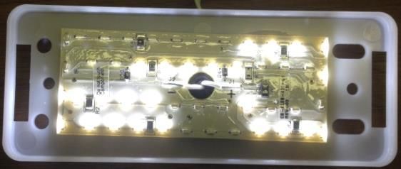
SUPER KING AIR 200 SERIES HALO 250/275 ICA MANUAL

                                [INTENTIONAL BLANK PAGE]

MANUAL No. 006-30                                                       REV. 3, DEC 2019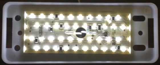
SUPER KING AIR 200 SERIES HALO 250/275 ICA MANUAL

                                             REVISION LOG
Rev.    Rev.
                                                     Changes                                     Page(s) Affected
No.     Date
                                                                                                    6 thru 29,
 1     07/12/13   Page numbering.                                                                  A1 thru A45,
                                                                                                   B1 thru B23
                  Over-speed warning switch description, inspection, removal & installation.          1, 2, 26
                  Exit sign above main cabin door; electric exit sign description, inspection,
                                                                                                     2, 23, 24
                  removal & installation.
                  Emergency lighting power supply description, removal & installation.              2, 3, 14, 15
                  Airworthiness limitations and life limits.                                             6
                  Placard illustrations.                                                             10 thru 12
                  Emergency lighting battery charge procedure, removal, inspection &
                                                                                                       14, 15
                  installation.
                  Ice mode stall warning tip gram force values; ground & flight cal. forms.          19 thru 21
                  Emergency light & LED indicator-caution light installations.                           24
                  Emergency lighting functional test form added.                                         25
                  Wing inspection times.                                                               28, 29
                                                                                                  1-5, 5.1, 12.1,
                                                                                                 24.7, 26.1-26.2,
 2     05/31/16   General information and Beechcraft AMM designations.
                                                                                                 27.2, 27.4, 33.1,
                                                                                                    34.1-34.3
                  King Air 250 and Pro Line Fusion information.                                  1, 2, 4, 5.1, 24.7
                                                                                                  2, 5, 7.1, 33.5
                  Removed Appendices A (IPC) & B (WD) & Ch. 7.
                                                                                                 Apdx. A, Apdx. B
                  Wiring diagram drawings.                                                               1
                  Airworthiness limitation information; wing structure airworthiness limits &    4.1-4.9, 5.1, 57.1-
                  inspections; Charts 3, 4A, 201, 57A & 57B deleted.                                    57.6
                  Engine fire extinguisher system airworthiness limits, replacement,             4.9, 5.1-5.4, 26.1-
                  inspections & servicing.                                                              26.2
                  Self-illuminating exit sign airworthiness limits & inspection.                 4.9, 5.1, 5.3, 33.1
                  Phase & Biennial inspection requirements and item descriptions                    5.1, 5.3, 5.4
                  High utilization inspection program.                                                5.1-5.2
                  Placard description; figure numbering; illustrations of emerg. light system
                                                                                                  11.1, 11.3-11.7
                  placards updated & added.
                  Tire pressures revised & added for 14,000-lb. airplane.                               12.1
                  Location information for emerg. light power supply; figure numbering.              24.1-24.8
                  Ice mode stall warning procedures & stall vane tip gram tolerances.                27.2-27.4
                  Electric exit sign inspection & information; figure numbering; “optional”       2, 3, 5.3, 33.2-
                  deleted.                                                                              33.5
 3     12/01/19   Halo 275 designation added.                                                        All pages
                  Introduction info. updated, drawings now ref. & not required for ICA                   1
                  IPC 006-40 & WDM 006-50 replace drawings.                                              5

MANUAL No. 006-30                                                                        REV. 3, DEC 2019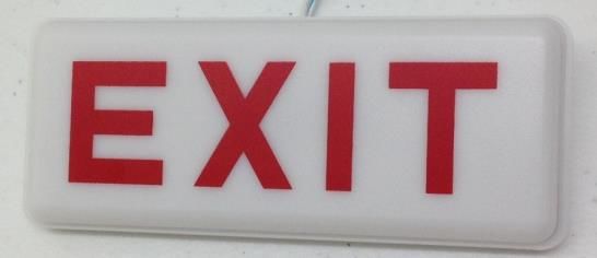
SUPER KING AIR 200 SERIES HALO 250/275 ICA MANUAL

Rev.    Rev.
                                                  Changes                                    Page(s) Affected
No.     Date
 3     12/01/19   Synchronized inspection info. with Beechcraft SIRM 98-39006 Rev. D.        4.3, 4.7, 4.8, 57.1
                  Synchronized inspection info. with BLR Aerospace BLR-200-950 Rev. Q.            4.6, 4.8
                  Updated inspection schedules; added schedule for Fusion airplanes per
                                                                                                  5.1-5.6
                  Beechcraft AMM 434-590168-0009 Rev. B0.
                  Battery specifications. battery life info. & 10 min. illumination added;
                                                                                                24.1-24.10
                  Emerg. lighting system on & cabin light loads updated.
                  Corrected CTA part no. 006-1002-0005-1                                            34.1

MANUAL No. 006-30                                                                    REV. 3, DEC 2019
SUPER KING AIR 200 SERIES HALO 250/275 ICA MANUAL
LIST OF EFFECTIVE PAGES
Rev.
Page Date
No.
Title 3 12/19
Record of
3 12/19
Revisions
Revision Log 3 12/19
List of Eff. Pages 3 12/19
1 thru 6 3 12/19
4.1 thru 4.10 3 12/19
5.1 thru 5.6 3 12/19
11.1 thru 11.8 3 12/19
12.1 thru 12.2 3 12/19
24.1 thru 24.10 3 12/19
26.1 thru 26.2 3 12/19
27.1 thru 27.6 3 12/19
33.1 thru 33.6 3 12/19
34.1 thru 34.4 3 12/19
57.1 thru 57.2 3 12/19
End 3 12/19
MANUAL No. 006-30 REV. 3, DEC 2019SUPER KING AIR 200 SERIES HALO 250/275 ICA MANUAL
[INTENTIONAL BLANK PAGE]
MANUAL No. 006-30 REV. 3, DEC 2019SUPER KING AIR 200 SERIES HALO 250/275 ICA MANUAL
INTRODUCTION
GENERAL
This manual provides Instructions for Continued Airworthiness (ICA) for Beechcraft Super King Air 200 series
airplanes modified by CenTex Aerospace’s (CTA) Halo 250 Conversion or Halo 275 Conversion as approved
under FAA Supplemental Type Certificate (STC) number SA11103SC. Both Halo 250 Conversion and Halo
275 Conversion add commuter category safety systems and equipment designed to enhance aircraft and
passenger safety. They also permit changing airplane category from normal to commuter category in order
to operate at higher approved weight limits. Refer to Description of Equipment on the following pages for
descriptions of each of the commuter category safety systems and equipment installed by the Halo 250/275
Conversion. The two STC options for airplane category are identified as follows:
Option 1: Airplane in normal category; no increase in takeoff weight limit (12,500 pounds).
Option 2: Airplane in commuter category; takeoff weight limit increases to 13,420 pounds for
Halo 250 Conversion or 14,000 pounds for Halo 275 Conversion.
When information in this manual applies to only one option, it will be specifically identified by option number.
This manual supplements the existing aircraft maintenance manual (AMM), Textron/Beechcraft Super King Air
200 Series Maintenance Manual, P/N 101-590010-19 and Textron/Beechcraft Super King Air Model
B200GT/B200CGT Fusion Maintenance Manual, P/N 434-590168-0009. References to these manuals shall
be made herein as “Beechcraft AMM” or simply “AMM.”
ASSOCIATED DRAWINGS
The following CenTex Aerospace drawings are provided with the STC modification kit. These drawings are
listed as reference and are not required for maintaining the continued airworthiness of the airplane. Contact
CenTex Aerospace to obtain a copy of any drawing listed below.
Number Title
006-0000-1000 INSTALLATION INSTRUCTIONS - KING AIR 200 SERIES
006-0000-2000 INSTALLATION INSTRUCTIONS - KING AIR 250
006-1001-0000 INSTALLATION, PLACARDS & MARKINGS, KING AIR 200 SERIES
006-1002-0000 INSTALLATION, OVERSPEED WARNING, KING AIR 200 SERIES
006-1003-0000 INSTALLATION, FLOOR PROXIMITY PATH MARKING, KING AIR 200 SERIES
006-1004-0000 INSTALLATION, EMERGENCY EXIT SIGN, KING AIR 200 SERIES
006-1005-0000 INSTALLATION, EMERGENCY LIGHTING, KING AIR 200 SERIES
006-1006-0000 INSTALLATION, TRIM OUT OF RANGE WARNING, KING AIR 200 SERIES
006-1009-0000 INSTALLATION, ENGINE FIRE EXTINGUISHER, KING AIR 200 SERIES
006-1010-0000 INSTALLATION, ICE MODE, STALL WARNING, KING AIR 200 SERIES
006-1011-0001 WIRING DIAGRAM – OVERSPEED WARNING
006-1011-0002 WIRING DIAGRAM – EMERGENCY LIGHTING
006-1011-0003 WIRING DIAGRAM – TRIM OUT-OF-RANGE
006-1011-0004 WIRING DIAGRAM – ENGINE FIRE EXTINGUISHER
006-1011-0005 WIRING DIAGRAM – ICE MODE STALL WARNING
PAGE 1
MANUAL No. 006-30 INTRODUCTION REV. 3, DEC 2019SUPER KING AIR 200 SERIES HALO 250/275 ICA MANUAL
DESCRIPTION OF EQUIPMENT
The safety systems and equipment installed on King Air 200 series aircraft for this STC are described below.
A. Placards and Markings:
New placards mark the switches, circuit breakers, and annunciator lights added as part of this
conversion. A new cabin door handle placard provides new door closing and opening markings that
comply with commuter category requirements. Two-inch wide color band placards outlining the exterior
borders of the cabin door and emergency exit window make these exits more visible to emergency
rescue personnel in case of an accident. See Chapter 11 for maintenance information.
B. Over-Speed Warning System:
The over-speed warning system provides the pilot with an aural warning anytime the airplane exceeds
the maximum operating speed or Mach number. For King Air models 200, 200C, A200, A200C, B200,
B200C, B200GT, and B200CGT, the warning horn automatically sounds at airspeeds above 259 KIAS
or an airspeed corresponding to 0.58 Mach and above.
NOTE: The CenTex over-speed warning system is optional on King Air models B200GT and B200CGT
or any other model equipped with Rockwell Collins Pro Line 21 or Pro Line Fusion avionics system,
which includes an aural over-speed warning.
For King Air models 200CT, 200T, A200CT, B200CT, and B200T, the warning horn automatically
sounds at airspeeds above 244 KIAS or an airspeed corresponding to 0.472 Mach and above. The
warning horn stops when the pilot reduces speed and the airspeed drops back under the limit.
The system uses an over-speed warning switch mounted in the center cockpit pedestal or behind the
instrument panel. The switch senses pitot and static pressures from lines connected directly into the
pilot’s pitot and static system lines. The switch is preset and is not adjustable. The warning horn is
located on the instrument panel glare shield. Power for the over-speed warning system comes from
the dual fed bus through a 5-amp circuit breaker in the copilot circuit breaker panel labeled O/S WARN.
A test switch allows the pilot or ground crew to test the system. The test switch is a momentary toggle
switch mounted in the pilot outboard sub panel and labeled OVERSPEED WARN TEST. See Chapter
34 for maintenance information.
In conjunction with the overspeed warning system, the STC permits adjustment of the Mach limit
"Barber Pole" on certain airspeed indicators from 0.52 to 0.58 Mach. This adjustment is optional for
mechanical airspeed indicators on King Air models 200, 200C, A200, A200C, B200, and B200C.
CenTex identifies adjusted airspeed indicators with the label "CenTex Mod 006-31." See Chapter 34
for airspeed indicator adjustment and calibration procedures.
C. Emergency Escape Path Markings:
Part of the overall cabin emergency lighting system, the emergency escape path markings are photo
luminescent strips positioned on the floor along both sides of the main cabin aisle starting at the main
cabin door entry and ending at the emergency exit window. This provides passengers and crew an
illuminated pathway to guide them to the nearest exit in dark or smoky conditions. The strips must be
charged prior to each flight as part of the pre-flight procedure. This can be done using cabin lighting or
sunlight. See Chapter 33 for maintenance information.
D. Illuminated Exit Signs:
Part of the overall cabin emergency lighting system, the illuminated exit signs identify where the cabin
exits are found. One exit sign is above the emergency exit window, and the second exit sign is on the
left aft cabin bulkhead, which leads to the main cabin door. If the airplane does not have a cabin
bulkhead, then the exit sign is located on the trim panel above the main cabin door. The exit signs are
either self-illuminating or electrically powered. The self-illuminating signs use phosphor coated tubes
filled with tritium gas that can last a long time without loss of brightness. Electrically powered exit signs
get power from the emergency lighting system. See the section below for a description of this system.
See Chapter 33 for maintenance information.
PAGE 2
MANUAL No. 006-30 INTRODUCTION REV. 3, DEC 2019SUPER KING AIR 200 SERIES HALO 250/275 ICA MANUAL
E. Cabin Emergency Lighting System:
The cabin emergency lighting system is a self-contained, battery-powered lighting system that
automatically activates when the airplane’s electrical power is lost, or when the airplane experiences a
deceleration of 2g’s or greater. The lighting system, together with the escape path markings and exit
signs, guide passengers to the nearest exit in the event of an emergency.
The lighting system has two LED flood lamps, one mounted in the cabin ceiling near the center of the
main cabin and another above the cabin door entryway. In addition, the system may also provide power
to the electrically powered exit signs described in the section above. Power to the lights and exit signs
(if installed) comes from a dedicated power supply containing two 12-volt sealed lead-acid batteries.
The power supply houses the batteries within an aluminum box mounted under the main cabin floor.
Charging for the batteries comes from the aircraft's dual fed electrical bus through a 5-amp circuit
breaker in the copilot circuit breaker panel labeled EMERG LIGHT. This circuit breaker can power the
lights and exit signs directly when the main aircraft battery switch is on.
Two switches control the emergency lighting system and provide the required functionality. A cabin
switch located next to one of the overhead flood lamps connects the power supply to the lights. This
switch allows the crew to turn the lights on or off. A guarded, three-position, cockpit control switch
located in the copilot sub-panel provides the pilot with the ability to arm or manually control the lights.
Two amber indicators located in the copilot instrument panel warn the pilot when the system switches
are not set properly for flight. The CABIN SW OFF indicator illuminates when the cabin switch is off.
The LT NOT ARMED indicator illuminates when the cockpit control switch is in either the ON or OFF
position. Both amber indicators extinguish when the cabin switch is ON and the control switch is in the
ARM position.
When exiting the airplane both the control switch and the cabin switch should be placed in the OFF
position. In the event that the lights are left on, the power supply has a built in timer relay that turns the
emergency cabin lights off automatically after 10 minutes. The crew can reset the timer relay by turning
the cabin switch OFF. Once reset, the crew can turn the cabin lights on again if needed. See Chapters
24 and 33 for maintenance information.
F. Takeoff Trim Out-of-Range Warning System:
The takeoff trim warning system alerts the pilot prior to takeoff by an aural warning when the elevator
trim tab is outside the normal takeoff range. Power to the system comes through the auto-feather
system switch. The warning system activates on the ground when the pilot places the auto-feather
switch in the ARM position and advances the left engine throttle lever past 90% N1. A roller, lever-
actuated micro-switch located in the cockpit pedestal, forward of the elevator trim wheel contacts a
trigger plate mounted on the elevator trim wheel, opposite the takeoff trim range marks. When elevator
trim is within the normal takeoff range, the roller remains in contact with the trigger plate, which presses
against the switch lever and keeps the switch contacts closed. If the pilot moves the elevator trim up
or down out of the takeoff range, the roller loses contact with the trigger plate, which opens the switch
contacts (extended with audible click) and activates the trim out-of-range warning horn. The system
deactivates after lift-off by means of the signal from the landing gear weight-on-wheels switch. In flight,
the elevator trim warning is inoperative. See Chapter 27 for maintenance information.
G. Engine Fire Extinguisher System:
The engine fire extinguisher system is identical to the optional engine fire extinguisher system provided
by the factory. Refer to Section 26-20-00 of the Beechcraft AMM for a description. See Chapter 26 for
maintenance information.
PAGE 3
MANUAL No. 006-30 INTRODUCTION REV. 3, DEC 2019SUPER KING AIR 200 SERIES HALO 250/275 ICA MANUAL
H. "Ice Mode" Stall Warning System for Flight in Icing Conditions:
The "ice mode" stall warning system alerts the pilot by an aural warning when the airplane's airspeed
drops to within 10 knots above the stalling speed of an airplane contaminated with ice. The existing
stall warning system does not have the capability to adjust for the effect that icing has on stall speed.
Ice accretion causes the wing to stall at a lower angle-of-attack and can result in a 15% to 20% increase
in stall speed.
This ice mode system activates automatically when the pilot identifies ice accumulation on the wing
and selects either SINGLE or MANUAL on the surface de-ice boot switch. A white indicator switch
located on the glare shield, labeled STALL WARNING ICE MODE, illuminates when the system is
active. The pilot can deactivate the system by depressing the switch.
Power for the ice mode system comes from the existing stall warning system. When activated, the ice
mode system diverts the signals from the existing stall lift computer located under the floor behind the
cockpit through a 24-pole switching relay to a new, ice mode stall lift computer installed in the center
cockpit pedestal. This second stall lift computer is calibrated at installation for the higher stall speeds
that occur when the aircraft experiences ice accumulations.
The system works with the same stall/lift vane and stall warning horn as the existing system. The ice
mode stall lift computer senses voltage from the stall/lift vane. When the output of the lift vane reaches
a preset voltage, the stall lift computer triggers the stall warning horn to sound. The initial sound of the
stall warning horn in the ice mode is a 1-Hertz pulsing tone. If angle-of-attack increases further, the
duration of the pulsing increases until the tone becomes constant. On airplanes with Rockwell Collins
Pro Line 21 or Fusion, the tone is constant.
The system has three different voltage settings, one for each flap position; which enables it to provide
accurate warning at each flap setting. These voltage settings are uniquely selected so that the effect
of ice on the wings is considered. With wing flaps up, the stall warning activates at approximately 20
knots higher airspeed in the ice mode.
When the pilot deactivates the ice mode system, the relay switches the input signals back to the existing
stall lift computer, which reverts back into the "normal mode" stall warning system. See Chapter 27 for
maintenance information.
I. Beechcraft King Air 250 and 250C with Rockwell Collins Pro Line 21 or Pro Line Fusion
Avionics System:
The Rockwell Collins adaptive flight displays (AFD), which consist of the two primary PFD screens and
a multi-function MFD screen, and the standby instrument (ESIS) have been updated in order to indicate
the airspeed values appropriate to the increased gross weight for airplanes operating in commuter
category under STC Option 2. These changes do not affect the system’s inspection or maintenance
procedures. Refer to the Beechcraft AMM for maintenance information.
PAGE 4
MANUAL No. 006-30 INTRODUCTION REV. 3, DEC 2019SUPER KING AIR 200 SERIES HALO 250/275 ICA MANUAL
AIRPLANE MAINTENANCE
Airworthiness limitations, inspection procedures, servicing information, and maintenance procedures provided
in this manual apply to the equipment and modifications associated with this STC and supplement the standard
aircraft maintenance manual (AMM); refer to the latest revision of the Beechcraft AMM. For King Air 200 series
aircraft modified by this STC, follow the inspection, servicing, and maintenance procedures in the AMM, except
as provided herein. This manual uses the same chapter numbering and general format as the AMM.
For standard aviation maintenance practices, such as cutting, splicing, and replacing wire, routing and securing
lines, inspecting electrical wiring and equipment, etc. use the techniques and practices found in FAA Advisory
Circular AC 43.13-1B/2B or later FAA approved revision.
REPLACEMENT PARTS
Refer to CenTex Aerospace Illustrated Parts Catalog (IPC) no. 006-40 for a list of commuter category safety
systems and equipment parts installed on the airplane. Contact CenTex Aerospace to order replacement parts.
WIRING DIAGRAMS
Refer to CenTex Aeropsace Wiring Diagram Manual (WDM) no. 006-50 for wiring details of the commuter
category safety systems and equipment installed on the airplane.
MANUAL UPDATES
A copy of this ICA Manual is provided with the STC upon installation. When changes to this ICA Manual are
made, CenTex Aerospace will provide updates to the registered airplane owner by email or direct mail. Contact
CenTex Aerospace to make other arrangements. If there is a change in airplane ownership or operator, please
notify CenTex Aerospace in order to keep all contact information current.
The changes to the ICA manual will be identified by revision number and date in the Revision Log. CenTex will
provide the owner with the revised pages, a Revision Log, and an updated List of Effective Pages. The owner,
or responsible party, will add or replace the pages affected by the revision and make an entry in the Record of
Revisions in order to document the update to the ICA Manual is accomplished.
ASSISTANCE
For assistance with continuing airworthiness issues or any other issues related to this STC, contact CenTex
Aerospace at the following address or telephone number.
CenTex Aerospace Inc.
7925 Karl May Drive
Waco, Texas 76708
(254) 752-4290
http://www.centex.aero/
PAGE 5
MANUAL No. 006-30 INTRODUCTION REV. 3, DEC 2019SUPER KING AIR 200 SERIES HALO 250/275 ICA MANUAL
[INTENTIONAL BLANK PAGE]
PAGE 6
MANUAL No. 006-30 INTRODUCTION REV. 3, DEC 2019SUPER KING AIR 200 SERIES HALO 250/275 ICA MANUAL
CHAPTER 4
The Airworthiness Limitations section is FAA approved and specifies maintenance required
under §§43.16 and 91.403 of the Federal Aviation Regulations unless an alternative program has
been FAA approved.
GENERAL
Beechcraft King Air 200 series airplanes modified by CenTex’s Halo 250/275 Conversion STC shall follow the
airworthiness limitations specified in Beechcraft Super King Air 200 Series Airworthiness Limitations Manual,
P/N 101-590010-453, except where noted by this Chapter.
The Halo 250/275 STC does not change any of the structural limitations that currently apply to the various
airplane configurations identified below in Airplane Configurations. Refer to Structural Limitations on the
following page in order to find the structural life limits and structural inspection times, intervals, and procedures
that apply to your airplane configuration.
AIRPLANE CONFIGURATIONS
The table below assigns a configuration number to each airplane modified by CenTex’s Halo 250/275 STC.
The configuration number, by row, includes each configuration item denoted by a black dot. Information about
each configuration item is specified below. Determine the configuration number that applies to your airplane
before going to Structural Limitations.
TABLE 4.1 - Airplane Configurations Defined
STC STC TENSION SHEAR BLR
CONFIG. OPTION 1 OPTION 2 WING WING WINGLET
1 ● ●
2 ● ●
3 ● ●
4 ● ●
5 ● ● ●
6 ● ● ●
7 ● ● ●
8 ● ● ●
STC OPTION 1
Any King Air 200 series airplane operating in normal category with a maximum takeoff weight of 12,500 pounds.
STC OPTION 2
Any King Air 200 series airplane operating in commuter category with a maximum takeoff weight of either 13,420
or 14,000 pounds.
PAGE 4.1
MANUAL No. 006-30 CHAPTER 4 REV. 3, DEC 2019SUPER KING AIR 200 SERIES HALO 250/275 ICA MANUAL
TENSION WING MODELS
Any King Air 200 series airplane with the original Beech "tension fitting" wing design, which include, but are not
limited to, King Air model 200 and B200 serial numbers BB-2 thru BB-1157, BB-1159 thru BB-1166, and BB-
1168 thru BB-1192;model 200C and B200C serial numbers BL-1 thru BL-72; model 200T and B200T serial
numbers BT-1 thru BT-30; model 200CT and B200CT serial numbers BN-1 thru BN-4. The tension wing
employs four bolts in tension at the upper and lower, forward spar and rear spar fittings to attach each outboard
wing to the center wing section. The main spar has a solid aluminum spar cap.
SHEAR WING MODELS
Any King Air 200 series airplane with the current Beech "shear fitting" wing design, which include, but are not
limited to, King Air model B200 serial numbers BB-1158, BB-1167, BB-1193 and up; model B200C serial
numbers BL-73 and up; model B200T serial numbers BT-31 and up; model B200CT serial numbers BN-5 and
up; model B200GT serial numbers BY-1 and up; and model B200CGT serial numbers BZ-1 and up. The shear
wing uses a double clevis and pin joint in place of the tension bolt at the lower, forward spar fitting. This "shear
fitting" plus the three tension bolts carried over from the original design attach the outboard wings to the center
wing section. The main spar has a fail-safe (layered and bonded) aluminum spar cap.
NOTE: Airplane serial numbers below BB-1335, BL-133 and BT-35 must have Beechcraft Kit 101-4050 bushing
replacements installed prior to installation of this STC.
BLR AEROSPACE WINGLETS
Any King Air model 200, 200C, B200, B200C, B200CGT or B200GT airplane equipped with BLR Aerospace's
Winglet System in accordance with STC SA01615SE. This also includes any King Air 250 series airplane and
any King Air model B200GT modified by BLR Aerospace’s Ultimate Performance Package under STC
SA02131SE. Refer to BLR Aerospace Document BLR-200-950, Instructions for Continued Airworthiness-King
Air 200 Winglet System, for more information about BLR winglets and the installation of Gurney flaps.
HALO 250/275 FLIGHT PROFILE
The Halo 250/275 flight profile is a typical executive flight profile in which the majority of the flight is spent above
a cruise altitude of 10,000 feet with a flight duration of one hour or more. The component life limits in this
Chapter are based on operating the airplane in the Halo 250/275 flight profile 95% of the time. Contact CenTex
Aerospace regarding airworthiness limitations for flight profiles that do not meet these criteria.
STRUCTURAL LIMITATIONS
The Halo 250/275 STC does not change the structural limitations that currently apply to these aircraft. The
appropriate structural limitations are identified below for each configuration number defined by Table 4.1.
CONFIGURATION NO. 1, 2, 3, 4, 5 OR 7
Refer to Beechcraft Airworthiness Limitations Manual, P/N 101-590010-453, for all structural limitations by
airplane serial number. Follow all structural inspection times, intervals, and procedures in accordance with the
Beechcraft manuals.
NOTE: BLR Aerospace requires an airplane in configuration no. 5 or 7 have Gurney flaps installed.
PAGE 4.2
MANUAL No. 006-30 CHAPTER 4 REV. 3, DEC 2019SUPER KING AIR 200 SERIES HALO 250/275 ICA MANUAL
CONFIGURATION NO. 6 OR 8
For an airplane that has BLR Aerospace Gurney flaps installed, refer to Beechcraft Airworthiness Limitations
Manual, P/N 101-590010-453, for all structural limitations by airplane serial number. Follow all structural
inspection times, intervals, and procedures in accordance with the Beechcraft manuals.
For an airplane that does NOT have Gurney flaps installed:
1) Refer to Tables 3.B. and 3.C. in Beechcraft Airworthiness Limitations Manual, P/N 101-590010-453, for
fuselage and tail structural limitations by airplane serial number. Follow the structural inspection times,
intervals, and procedures prescribed for these areas in accordance with the Beechcraft manuals.
2) Refer to Table 4.2 in this manual for wing structural limitations by airplane serial number. The life limits
in Table 4.2 supersede the life limits in Table 3.D. Wing and Associated Structure in Beechcraft
Airworthiness Limitations Manual, P/N 101-590010-453.
3) Refer to Table 4.3 in this manual for wing inspection times and intervals. Perform the wing inspection
procedures required by Chapter 57-17-02 and Chart 201 in Beechcraft Structural Inspection and Repair
Manual, P/N 98-39006 Revision D, or subsequent, in accordance with the inspection times and intervals
identified in Table 4.3. The inspection times and intervals in Table 4.3 supersede the times and intervals
in Chart 201 of the Beechcraft manual.
PAGE 4.3
MANUAL No. 006-30 CHAPTER 4 REV. 3, DEC 2019SUPER KING AIR 200 SERIES HALO 250/275 ICA MANUAL
[INTENTIONAL BLANK PAGE]
PAGE 4.4
MANUAL No. 006-30 CHAPTER 4 REV. 3, DEC 2019SUPER KING AIR 200 SERIES HALO 250/275 ICA MANUAL
TABLE 4.2 – Wing and Associated Structure for Configuration no. 6 or 8
without Gurney Flaps
Component Effectivity Life
(1) Wing Center Section BB-1158, BB-1167, BB-1193 thru 18,000 hours unless
BB-1203, BB-1207 thru BB-1295, Beechcraft Kit no. 101-1200 is
BB-1297 thru BB-1301, BB-1303, installed.
BB-1304, BB-1306 thru BB-1308,
BB-1310 thru BB-1313, BB-1316 thru
BB-1334, BL-124 thru BL-127,
BL-129, BL-131, and BL-132 with
Beechcraft Kit no. 101-4050 installed;
BB-1335 thru BB-1337, BB-1344 thru
BB-1375, BB-1377 thru BB-1382,
BB-1385 thru BB-1433, and BB-1435
thru BB-1512;
BL-133 thru BL-141
(2) Wing Center Section BB-1158, BB-1167, BB-1193 thru Life not limited provided
BB-1203, BB-1207 thru BB-1295, inspections identified in
BB-1297 thru BB-1301, BB-1303, Table 4.3 of this manual are
BB-1304, BB-1306 thru BB-1308, performed.
BB-1310 thru BB-1313, BB-1316 thru
BB-1334, BL-124 thru BL-127,
BL-129, BL-131, and BL-132 with
Beechcraft Kit no. 101-4050 and
Kit no. 101-1200 installed;
BB-1335 thru BB-1337, BB-1344 thru
BB-1375, BB-1377 thru BB-1382,
BB-1385 thru BB-1433, BB-1435 thru
BB-1512, and BL-133 thru BL-141
with Beechcraft Kit no. 101-1200
installed;
BB-1513 and after;
BL-142 and after;
BY-1 and after;
BZ-1 and after
(3) Outboard Wing Structure BB-1158, BB-1167, BB-1193 thru 23,750 hours unless Spar Cap
BB-1203, BB-1207 thru BB-1295, is replaced with Beechcraft P/N
BB-1297 thru BB-1301, BB-1303, 101-110085-1 and -2.
BB-1304, BB-1306 thru BB-1308,
BB-1310 thru BB-1313, BB-1316 thru
BB-1334, BL-124 thru BL-127,
BL-129, BL-131, and BL-132 with
Beechcraft Kit no. 101-4050 installed;
BB-1335 thru BB-1337, BB-1344 thru
BB-1375, BB-1377 thru BB-1382,
BB-1385 thru BB-1433, BB-1435 thru
BB-1539, BB-1541, and BB-1542;
BL-133 thru BL-141
PAGE 4.5
MANUAL No. 006-30 CHAPTER 4 REV. 3, DEC 2019SUPER KING AIR 200 SERIES HALO 250/275 ICA MANUAL
TABLE 4.2 (continued) – Wing and Associated Structure for Configuration no. 6 or 8
without Gurney Flaps
Component Effectivity Life
(4) Outboard Wing Structure BB-1158, BB-1167, BB-1193 thru Life not limited provided
BB-1203, BB-1207 thru BB-1295, inspections identified in Table
BB-1297 thru BB-1301, BB-1303, 4.3 of this manual are
BB-1304, BB-1306 thru BB-1308, performed.
BB-1310 thru BB-1313, BB-1316 thru
BB-1337, BB-1344 thru BB-1375,
BB-1377 thru BB-1382, BB-1385 thru
BB-1433, BB-1435 thru BB-1539,
BB-1541, BB-1542, BL-124 thru BL-
127, BL-129, and BL-131 thru BL-141
with Beechcraft P/N 101-110085-1
and -2 Spar Cap installed;
BB-1540, BB-1543 and after;
BL-141 and after;
BY-1 and after;
BZ-1 and after
(5) Wing to Fuselage Attach All airplanes in configuration no. 6 or 19,500 hours unless
Angles, Beechcraft P/N 101- 8 Beechcraft Kit no. 101-1202 is
120032-3 and -4 installed.
(6) Wing to Fuselage Attach All airplanes in configuration no. 6 or 30,000 hours
Angles, Beechcraft P/N 101- 8 with Beechcraft Kit no. 101-1202
120032-3 and -4 installed
(7) (*) Upper Forward, Upper All airplanes in configuration no. 6 or Replace at 20 years of service
and Lower Aft Wing Bolts and 8 or 20,000 hours, whichever
Nuts occurs first (Beechcraft Kit no.
101-4025 & Kit no. 101-4026).
(8) Lower Forward Wing Bolts All airplanes in configuration no. 6 or Replace at 5 years or anytime
and Nuts 8 removed (Beechcraft Kit no.
101-4083).
NOTE: (*) These parts are not practical to mark with a part number/serial number. If removed before the end
of its life limit, bag the part and identify it with the accumulated hours/cycles in service. Maintain records to
ensure compliance with the life limit.
NOTE: The limitations in Table 4.2 are equivalent to Table 6-2 in BLR Aerospace ICA Document BLR-200-950.
PAGE 4.6
MANUAL No. 006-30 CHAPTER 4 REV. 3, DEC 2019SUPER KING AIR 200 SERIES HALO 250/275 ICA MANUAL
TABLE 4.3 – Wing Inspection Schedule for Configuration no. 6 or 8
without Gurney Flaps
Recurring Component
Index Initial
Inspection Area Inspection Replacement
No. (*) Inspection
Interval Schedule
1. Lower forward (main) spar lugs 15,000 hours 6,000 hours None
2. Outboard wing panel lower 15,000 hours 3,000 hours None
forward spar cap P/N 101-
110085-1 and -2
(spar assy. P/N 101-110084)
3. Center section lower forward 18,000 hours 3,000 hours None
spar cap
4. Center section belly skin 10,500 hours 3,000 hours None
5. Center section lower aft spar 15,000 hours 1,500 hours None
See Note 1 See Note 2
6. Center section and outboard 15,000 hours 1,500 hours None
wing panel aft spar lower fittings See Note 2
See Note 1
7. Lower forward main spar clevis 5 years 5 years None
fittings
8. Outboard wing panel upper and 5 years Annually Refer to Table 4.2
lower main spar caps Components (3) &
(4) in this manual
9. Lower forward wing bolt N/A N/A Refer to Table 4.2
Component (8) in
this manual
10. Upper forward, upper and lower First scheduled First scheduled Refer to Table 4.2
aft wing bolts inspection after inspection after Component (7) in
date on airplane’s wing bolt this manual
Standard replacement
Airworthiness
Certificate
11. Flat surfaces, depressions, 5 years 5 years None
counterbores, and bolt bores at
the upper forward, upper and
lower aft wing joining points
12. Wing bolts at the upper forward, 5 years 5 years Refer to Table 4.2
upper and lower aft wing attach Component (7) in
points this manual
13. Wing forward spar angle 18,000 hours 3,000 hours None
(*) The index number in this table corresponds to the index number in Chart 201, Chapter 57-17-02 of
Beechcraft Structural Inspection and Repair Manual, P/N 98-39006 Rev. D (SIRM).
NOTE 1 (per SIRM): The installation of Beechcraft Kit no. 101-4077 is MANDATORY. The inspection should
entail wing B.L. 123.309 to B.L. 28.72.
PAGE 4.7
MANUAL No. 006-30 CHAPTER 4 REV. 3, DEC 2019SUPER KING AIR 200 SERIES HALO 250/275 ICA MANUAL
TABLE 4.3 (continued) – Wing Inspection Schedule for Configuration no. 6 or 8
without Gurney Flaps
NOTE 2 (per SIRM): This recurring inspection interval does not require fastener removal, but requires an Eddy
Current inspection to be performed on the vertical, aft and fwd flange of the rear spar shown in Figure 205,
View A-A, Chapter 57-17-02 of Beechcraft Structural Inspection and Repair Manual, P/N 98-39006 Rev. D.
NOTE 3: The inspection times and intervals in Table 4.3 are equivalent to those in Table 6-1 in BLR Aerospace
ICA Document BLR-200-950.
NOTE 4: For each inspection area, perform the inspection according to the inspection method required by
Chapter 57-17-02 and Chart 201 in Beechcraft Structural Inspection and Repair Manual, P/N 98-39006 Rev. D
or subsequent.
PAGE 4.8
MANUAL No. 006-30 CHAPTER 4 REV. 3, DEC 2019SUPER KING AIR 200 SERIES HALO 250/275 ICA MANUAL
MISCELLANEOUS LIMITATIONS
ENGINE FIRE EXTINGUISHER SYSTEM
The engine fire extinguisher component life limits for a King Air 200 series airplane modified by CenTex’s Halo
250/275 Conversion are specified below. The limitations specified in Table 4.4 apply to all airplane
configurations.
TABLE 4.4 - Engine Fire Extinguisher System Component Life Limits
Component Life
Engine Fire Extinguisher The cylinder must be requalified and remarked every 5 years in accordance
Cylinder (Bottle) with Title 49 CFR 180.205 for DOT specification 4DS cylinders, except the
retest pressure must be that stamped on the cylinder.
A cylinder that is filled before the requalification becomes due may remain
in service on the airplane past its’ requalification date until it is either
emptied or otherwise removed for maintenance as specified in Chapter 26
of this manual. A cylinder that has been emptied and is past its’ 5-year
requalification date, may not be serviced or re-filled until it has been
hydrostatically tested and requalified by a person authorized under the
appropriate provisions of 49 CFR.
Engine Fire Extinguisher The cartridge life is 6 years, which includes the combined time in storage
Cartridge (Squib) and in service, with the time in service (installed) limited to a maximum life
of 4 years. Exceptions are noted in Chapter 26 of this manual.
SELF ILLUMINATING EXIT SIGN
The self-illuminating exit sign component life limit for a King Air 200 series airplane modified by CenTex’s Halo
250/275 Conversion is specified below. This limitations specified in Table 4.5 apply to all airplane
configurations.
TABLE 4.5 - Self-Illuminating Exit Sign Component Life Limits
Component Life
Emergency Exit Signs, Self- Replace the exit sign 7 years from the date of manufacture as stated on the
Illuminating sign, or test the exit sign annually, beginning at seven years, and replace
when the brightness drops below 160 microlamberts in accordance with 14
CFR 23.811. Refer to Chapter 33 of this manual for the test procedure.
PAGE 4.9
MANUAL No. 006-30 CHAPTER 4 REV. 3, DEC 2019SUPER KING AIR 200 SERIES HALO 250/275 ICA MANUAL
[INTENTIONAL BLANK PAGE]
PAGE 4.10
MANUAL No. 006-30 CHAPTER 4 REV. 3, DEC 2019SUPER KING AIR 200 SERIES HALO 250/275 ICA MANUAL
CHAPTER 5
TIME LIMITS/MAINTENANCE CHECKS
GENERAL
The overhaul and replacement schedule and inspection programs in this chapter apply to the equipment
installed as part of this STC. The format of the inspection programs is the same as those in Beechcraft’s
maintenance manuals and maintenance manual supplements. The terminology (phase, detailed, biennial, etc.)
used in this chapter has the same meaning as Beechcraft’s terminology. Use the AMM guidelines when
following the replacement and inspection schedules specified herein. Use the Halo 250/275 Equipment
Inspection sheets in this chapter to record the completion of each required inspection item at the time of the
scheduled inspection (phase 1, 2, 3, etc.). Retain the inspection sheets with the normal aircraft maintenance
records.
OVERHAUL AND REPLACEMENT SCHEDULE
For all airplanes, overhaul or replace the following items per the recommended period.
ITEM OVERHAUL OR REPLACE
Emergency lighting system batteries On condition; refer to Chapter 24
Engine Fire Extinguisher Cylinder Refer to Chapter 4, Table 4.4
Engine Fire Extinguisher Cartridge (Squib) Refer to Chapter 4, Table 4.4
Exit Sign, Self-Illuminated Refer to Chapter 4, Table 4.5
Wing and Associated Structure Safelife Refer to Chapter 4, Structural Limitations
SCHEDULED INSPECTION PROGRAM - PHASE / BIENNIAL
For Super King Air 200 series airplanes following a scheduled inspection program in Beechcraft Maintenance
Manual no. 101-590010-19, inspect the Halo 250/275 equipment items during the inspection marked below.
NOTE: See the Halo 250/275 Equipment Inspection sheets in this chapter for inspection details.
PHASE INSP BIENNIAL INSP
ITEM
1 2 3 4 INT COMP
Cabin door & emergency exit exterior marking X X X X X X
Cabin door handle placard X X X X X X
Cockpit placards X X X X X X
Emergency lighting batteries operational check X X X X X X
Emergency lighting power supply & batteries X X
Emergency lighting system LED indicator caution lights X X
Emergency lighting system operational check X X
Emergency lights X X
Engine fire extinguisher X X X X X
Engine fire extinguisher operational check X X X X X X
Engine fire extinguisher functional test X X
Escape path marking strips X X X X X X
Exit sign, self-illuminated X X X X X X
Exit sign, electric X X
PAGE 5.1
MANUAL No. 006-30 CHAPTER 5 REV. 3, DEC 2019SUPER KING AIR 200 SERIES HALO 250/275 ICA MANUAL
PHASE INSP BIENNIAL INSP
ITEM
1 2 3 4 INT COMP
Ice mode stall warning switch, lift computer & relay X X
Ice mode stall warning system operational check X X
Over-speed pressure switch, horn, wiring, lines & fittings X X
Over-speed warning system operational check X X
Takeoff trim warning switch & horn X X
Takeoff trim warning system operational check X X
SCHEDULED INSPECTION PROGRAM - DETAILED
For Super King Air B200GT/B200CGT Fusion airplanes following a scheduled inspection program in
Textron/Beechcraft Maintenance Manual no. 434-590168-0009, inspect the Halo 250/275 equipment items
during the inspection marked below.
NOTE: See the Halo 250/275 Equipment Inspection sheets in this chapter for inspection details.
DETAILED INSP
ITEM
1 2 3 4
Cabin door & emergency exit exterior marking X X X X
Cabin door handle placard X X X X
Cockpit placards X X X X
Emergency lighting batteries operational check X X X X
Emergency lighting power supply & batteries X
Emergency lighting system LED indicator caution lights X
Emergency lighting system operational check X
Emergency lights X
Engine fire extinguisher X
Engine fire extinguisher operational check X X X X
Engine fire extinguisher activation check X
Escape path marking strips X X X X
Exit sign, self-illuminated X X X X
Exit sign, electric X
Ice mode stall warning switch, lift computer & relay X
Ice mode stall warning system operational check X
Over-speed pressure switch, horn, wiring, lines & fittings X
Over-speed warning system operational check X
Takeoff trim warning switch & horn X
Takeoff trim warning system operational check X
PAGE 5.2
MANUAL No. 006-30 CHAPTER 5 REV. 3, DEC 2019SUPER KING AIR 200 SERIES HALO 250/275 ICA MANUAL
HIGH UTILIZATION INSPECTION PROGRAM (HUIP)
For Super King Air B200 series airplanes using Beechcraft’s high utilization inspection program (HUIP) per
Maintenance Manual Supplement, P/N 101-590010-559, inspect the Halo 250/275 equipment items during the
inspection marked below.
NOTE: See the Halo 250/275 Equipment Inspection sheets in this chapter for inspection details.
DETAILED INSP ROUTINE
ITEM
1 2 3 4 INSP
Cabin door & emergency exit exterior marking X X X X X
Cabin door handle placard X X X X X
Cockpit placards X X X X X
Emergency lighting batteries operational check X X X X X
Emergency lighting power supply & batteries X
Emergency lighting system LED indicator caution lights X
Emergency lighting system operational check X
Emergency lights X
Engine fire extinguisher X
Engine fire extinguisher operational check X X X X X
Engine fire extinguisher activation check X
Escape path marking strips X X X X X
Exit sign, self-illuminated X X X X X
Exit sign, electric X
Ice mode stall warning switch, lift computer & relay X
Ice mode stall warning system operational check X
Over-speed pressure switch, horn, wiring, lines & fittings X
Over-speed warning system operational check X
Takeoff trim warning switch & horn X
Takeoff trim warning system operational check X
PAGE 5.3
MANUAL No. 006-30 CHAPTER 5 REV. 3, DEC 2019SUPER KING AIR 200 SERIES HALO 250/275 ICA MANUAL
[INTENTIONAL BLANK PAGE]
PAGE 5.4
MANUAL No. 006-30 CHAPTER 5 REV. 3, DEC 2019SUPER KING AIR 200 SERIES HALO 250/275 ICA MANUAL
HALO 250/275 EQUIPMENT INSPECTION
Owner ___________________________________ Total Time __________ Total Cycles _________
W.O. No. _________________________________ Date In ____________ Date Out ____________
Serial No. ______________ Reg. No. __________ STC Installed TIS ________ Cycles ________
Inspection (1, 2, 3, 4, INT, COMP): _______________
NOTE: Inspect only the items required by the applicable phase or other inspection as designated by an “X” in
the inspection program table. Write “N/A” if an item is not required according for the applicable inspection.
A. PILOT COMPARTMENT REFERENCE MECH INSP
1. COCKPIT PLACARDS - Check placards for proper adhesion, visibility,
006-30 Ch. 11
signs of damage.
2. TAKEOFF TRIM WARNING SWITCH & HORN - Check for security of
006-30 Ch. 27
attachment, signs of damage or wear, and proper switch position.
3. ICE MODE STALL WARNING SWITCH, LIFT COMPUTER & RELAY -
006-30 Ch. 27
Check for damage to wiring, loose connectors, and security of attachment.
4. EMERGENCY LIGHT SYSTEM LED INDICATOR CAUTION LIGHTS -
006-30 Ch. 33
Check for security of attachment and inoperative LEDs.
5. OVER-SPEED PRESSURE SWITCH, HORN, WIRING, LINES & 006-30 Ch. 34
FITTINGS - Check for security of attachment, signs of damage, and leaks. MM 34-00-00
B. CABIN SECTION
1. CABIN DOOR & EMERGENCY EXIT EXTERIOR MARKING - Check 2-
006-30 Ch. 11
inch color band for proper adhesion, visibility, signs of damage.
2. CABIN DOOR HANDLE PLACARD - Check for security, proper
006-30 Ch. 11
adhesion, visibility, signs of damage.
3. EMERGENCY LIGHTS - Check for security of attachment, signs of
006-30 Ch. 33
damage, and inoperative LEDs.
4. EMERGENCY LIGHTING POWER SUPPLY & BATTERIES - Check for
006-30 Ch. 24
security of attachment, damage to wiring, and battery condition.
5. ESCAPE PATH MARKING STRIPS - Check photo-luminescent strips
006-30 Ch. 33
for damage and clean strips.
6. EXIT SIGN, SELF ILLUMINATED - Check for security of attachment. 006-30 Ch. 33
7. EXIT SIGN, ELECTRIC - Check for security of attachment, signs of
006-30 Ch. 33
damage, and inoperative LEDs.
C. LEFT WING CENTER SECTION
1. ENGINE FIRE EXTINGUISHER – Inspect plumbing for security of MM 26-20-00,
attachment. 001
MM 26-20-03,
2. ENGINE FIRE EXTINGUISHER – Check fire bottle pressure gage.
301
3. ENGINE FIRE EXTINGUISHER – Check for presence of activation
MM 26-20-00,
voltage to the cartridge/squib. Perform the EXTINGUISHER ACTIVATION
501
CHECK procedure.
D. RIGHT WING CENTER SECTION
1. ENGINE FIRE EXTINGUISHER – Inspect plumbing for security of MM 26-20-00,
attachment. 001
MM 26-20-03,
2. ENGINE FIRE EXTINGUISHER – Check fire bottle pressure gage.
301
3. ENGINE FIRE EXTINGUISHER – Check for presence of activation
MM 26-20-00,
voltage to the cartridge/squib. Perform the EXTINGUISHER ACTIVATION
501
CHECK procedure.
PAGE 5.5
MANUAL No. 006-30 CHAPTER 5 REV. 3, DEC 2019SUPER KING AIR 200 SERIES HALO 250/275 ICA MANUAL
HALO 250/275 EQUIPMENT INSPECTION (continued)
E. OPERATIONAL INSPECTION REFERENCE MECH INSP
1. TAKEOFF TRIM WARNING SYSTEM - Conduct "System Functional
006-30 Ch. 27
Test"
2. ICE MODE STALL WARNING SYSTEM - Conduct "System
006-30 Ch. 27
Operational Test"
3. EMERGENCY LIGHTING SYSTEM - Conduct "Emergency Lighting
006-30 Ch. 33
System Functional Test"
4. EMERGENCY LIGHTING BATTERIES - Conduct “Checking Battery
006-30 Ch. 24
Charge”
5. OVER-SPEED WARNING SYSTEM - Conduct "System Functional 006-30 Ch. 34
Test" MM 34-00-00
6. ENGINE FIRE EXTINGUISHERS - Perform system test according to
instructions found in the Super King Air 200/B200 Pilot’s Operating POH/AFM
Handbook and FAA Approved Airplane Flight Manual (POH/AFM).
NOTE: "MM" refers to the Super King Air 200 Maintenance Manual section specified.
INSPECTION COMPLETED
I certify that this inspection was performed in accordance with the CenTex Halo 250/275 STC Inspection
Program and that the airplane is approved for return to service:
MECHANIC: _______________________________ CREW CHIEF: _______________________________
INSPECTOR: _______________________________ DATE: ____________________________________
PAGE 5.6
MANUAL No. 006-30 CHAPTER 5 REV. 3, DEC 2019SUPER KING AIR 200 SERIES HALO 250/275 ICA MANUAL
CHAPTER 11
PLACARDS AND MARKINGS
PLACARDS AND MARKINGS - DESCRIPTION
The placards and markings added to the airplane for this STC are typically located in the areas indicated in
Figure 11.1 below. Interior placards are in locations C thru F. Exterior placards are in locations A and B.
NOTE: Exact locations may vary as allowed by the installation.
PLACARDS AND MARKINGS - MAINTENANCE PRACTICES
Inspect placards and markings for damage and wear. Replace placards or markings that become illegible or
start peeling or delaminating.
Every time the airplane is repainted or touched up, inspect the cabin door & emergency exit window borders,
making sure they are not covered with paint.
Figure 11.1 - Placard and Marking Locations
PAGE 11.1
MANUAL No. 006-30 CHAPTER 11 REV. 3, DEC 2019SUPER KING AIR 200 SERIES HALO 250/275 ICA MANUAL
INTERIOR PLACARDS AND MARKINGS
Location C - Instrument Panel:
Pilot Side, Lower Left:
Copilot Side, Lower Left:
Alternate fire detector/ extinguisher test switch placards:
PAGE 11.2
MANUAL No. 006-30 CHAPTER 11 REV. 3, DEC 2019SUPER KING AIR 200 SERIES HALO 250/275 ICA MANUAL
Copilot Side, Lower Right:
Copilot Side:
Alternate emergency light control switch configuration:
PLACARD
INDICATORS, EMERGENCY
EMERGENCY
CABIN LIGHT CABIN LIGHT (REF)
LT NOT CABIN
ARMED SW OFF
OFF
ARM
ON
SWITCH, EMERGENCY
PLACARD CABIN LIGHT (REF)
PAGE 11.3
MANUAL No. 006-30 CHAPTER 11 REV. 3, DEC 2019SUPER KING AIR 200 SERIES HALO 250/275 ICA MANUAL
Emergency light control switch configuration for airplane with Pro Line 21 or Pro Line Fusion avionics; or as
an alternate configuration. Pilot side, lower, left:
ON
AVIONICS ENG ARM
MASTER AUTO
POWER IGN
OFF
OFF LEFT RIGHT
ENGINE ANTI-ICE
LEFT RIGHT
ON
MASTER SWITCH
OFF
ESIS EMERGENCY CABIN LIGHTS
LT NOT CABIN ACTUATORS
ON ARMED SW OFF STANDBY
OFF
OFF ARM
ON MAIN
TEST
IGNITION AND
ENGINE START
AUTOFEATHER PROP GOV
LEFT RIGHT
ON ARM TEST
OFF OFF
STARTER ONLY TEST OFF
Location D - Copilot Circuit Breaker Panel:
Circuit breaker panel for airplane with Pro Line Fusion avionics (Pro Line 21 similar).
ENGINES AVIONICS
LIGHTS WARNINGS WEATHER
FLIGHT ELECTRICAL
ENVIRONMENTAL
FURNISHINGS
EMERG
PLACARD 5
PLACARD
LIGHT
ESIS
CIRCUIT BREAKER,
EMERGENCY CABIN LIGHT (REF)
PAGE 11.4
MANUAL No. 006-30 CHAPTER 11 REV. 3, DEC 2019SUPER KING AIR 200 SERIES HALO 250/275 ICA MANUAL
Circuit breaker panel for airplane with standard avionics (Garmin G1000 similar).
Location F - Overhead Light Panel
The "COMMUTER" placard is only installed for STC Option 2. For STC Option 1, there is no change to the
existing placard.
PAGE 11.5
MANUAL No. 006-30 CHAPTER 11 REV. 3, DEC 2019SUPER KING AIR 200 SERIES HALO 250/275 ICA MANUAL
Location E - Cabin Door Handle
Standard Model Cabin Door:
Cargo Model Cabin Door:
PAGE 11.6
MANUAL No. 006-30 CHAPTER 11 REV. 3, DEC 2019SUPER KING AIR 200 SERIES HALO 250/275 ICA MANUAL
EXTERIOR PLACARDS AND MARKINGS
Location A - Cabin Door:
Standard Model Cabin Door:
Cargo Model Cabin Door:
Location B - Emergency Exit:
PAGE 11.7
MANUAL No. 006-30 CHAPTER 11 REV. 3, DEC 2019SUPER KING AIR 200 SERIES HALO 250/275 ICA MANUAL
[INTENTIONAL BLANK PAGE]
PAGE 11.8
MANUAL No. 006-30 CHAPTER 11 REV. 3, DEC 2019SUPER KING AIR 200 SERIES HALO 250/275 ICA MANUAL
CHAPTER 12
SERVICING
GENERAL
In addition to the servicing information and procedures specified in the Beechcraft AMM, follow the procedures
below for equipment installed as part of this STC.
SCHEDULED SERVICING - MAINTENANCE PRACTICES
TIRES
If the airplane is operating in normal category under STC Option 1, then follow the tire servicing procedures
in Section 12-20-00 of the AMM.
If the airplane is operating in commuter category under STC Option 2, follow the tire servicing procedures in
Section 12-20-00 of the AMM except for the specific tire servicing information noted below.
For operations at gross weights above 12,500 pounds, the airplane is equipped with one of the following types
of nose and main wheel tires. Regularly check tire pressures for proper inflation. Inflate the tires to the
pressure specified for each type.
Nose Wheel Tire Pressure
22 X 6.75-10, 8-ply 55 - 60 psi
Type III 6.50-10, 6-ply 55 - 60 psi
Pressure Pressure
Main Wheel Tires at 13,420 Lbs. at 14,000 Lbs.
Max. Weight Max. Weight
Type VII 18 X 5.5, 10-ply 110 ± 4 psi N/A
19.5 X 6.75-8, 10-ply 95 ± 2 psi N/A
22 X 6.75-10, 8-ply 67 ± 2 psi 70 ± 2 psi
Type III 6.50-10, 8-ply 67 ± 2 psi 70 ± 2 psi
CAUTION: Do not intermix tire types on the main landing gear.
NOTE: For unloaded tire pressure, subtract 3 psi from the above value.
EMERGENCY LIGHTING SYSTEM BATTERIES
The emergency lighting system batteries are sealed, lead-acid batteries that do not require electrolyte
servicing. See Chapter 24 for maintenance practices.
PAGE 12.1
MANUAL No. 006-30 CHAPTER 12 REV. 3, DEC 2019SUPER KING AIR 200 SERIES HALO 250/275 ICA MANUAL
[INTENTIONAL BLANK PAGE]
PAGE 12.2
MANUAL No. 006-30 CHAPTER 12 REV. 3, DEC 2019SUPER KING AIR 200 SERIES HALO 250/275 ICA MANUAL
CHAPTER 24
ELECTRICAL POWER
EMERGENCY LIGHTING SYSTEM POWER SUPPLY - MAINTENANCE PRACTICES
The emergency lighting system power supply has two sealed, lead-acid batteries connected in series.
Nominal voltage is 12 volts per battery. Battery charging occurs during normal ground or flight operations or
any time the main aircraft battery switch is on. Airplanes used on a regular basis have no special charging
requirements.
BATTERY SPECIFICATIONS
The batteries used in the emergency lighting system power supply may be replaced with any battery that
meets or exceeds the following specifications:
Battery Type: Rechargeable, Sealed Lead Acid (SLA)
Nominal Voltage: 12 volts (6 cells)
Nominal Capacity: 0.8 AH (20-hour rate, 40 mA to 10.5 volts)
Size & Weight: 3.78 X .98 X 2.44 inches; 0.8 pounds
Battery Case: Impact resistant, ABS Plastic (UL 94-HB)
Terminal Type: WL, insulated wire leads with Amp 2-circuit plug
Max. Discharge Current: 2.4 amps
Operating Temp.: -40oF to +140oF
The following batteries are examples of acceptable replacements: Power Sonic PS-1208WL, Universal
Power Group (UPG) UB1208p, Duracell Ultra SLAA12-0.8WL.
BATTERY LIFE & STORAGE
Battery life depends on cyclic use, operating temperatures, and charging method. The emergency lighting
system batteries can last in the range of 3 to 5 years. Because of variations in battery usage, CenTex
recommends replacing the batteries every 36 calendar months from the time they are installed. However,
this may be done at the operator’s discretion. It is required to replace the batteries if they do not pass the
battery inspection specified on page 24.3 or when they do not provide proper emergency light illumination as
noted below.
The emergency lighting system batteries will discharge over time if the airplane is not flown regularly. If the
airplane is not to be operated for more than a six month period, the batteries should be removed and kept in
a clean and dry location. Storage temperature is ideally 60 to 75oF. Charge the batteries within six months
of storage in order to avoid permanent loss of capacity.
CHECKING BATTERY CHARGE
Check the battery charge level by turning the cabin emergency light switch to ON. Emergency lights and
optional electrically powered exit signs (if installed) should illuminate at or near full strength for at least 10
minutes. If the lights are dim or out, charge the batteries using the onboard charging procedure below. If the
lights are still dim after charging, remove the batteries, follow the inspection procedure, and replace as needed.
NOTE: Illumination of emergency lights and exit signs under emergency battery power can be judged by
comparing to full strength (28 VDC) illumination as follows.
PAGE 24.1
MANUAL No. 006-30 CHAPTER 24 REV. 3, DEC 2019SUPER KING AIR 200 SERIES HALO 250/275 ICA MANUAL
Full Strength Illumination: 1) Main battery switch - ON
2) Apply external power to airplane (if necessary)
3) Cockpit control switch - ON
4) Cabin light switch - ON
Battery Power Illumination: 5) Cockpit control switch - OFF
BATTERY CHARGING ON AIRPLANE
Turn on the main battery switch and connect external power to the airplane.
Make sure the EMERG LIGHT circuit breaker is pushed in.
Place the EMERG CABIN LT control switch in the ARM position.
Allow batteries to charge for one hour.
Turn off the main battery switch and disconnect external power.
Check the battery charge level.
POWER SUPPLY REMOVAL
The power supply for the emergency lighting system is located under the floor, at one of several locations:
Behind the main spar, on the right side of the fuselage. See Figure 24.1.
Under the center aisle panel at F.S. 188. See Figure 24.2.
Under the center aisle panel at F.S. 207. See Figure 24.3.
Under the center aisle panel at F.S. 246 (not pictured).
Under the center aisle panel at F.S. 278. See Figure 24.4.
To access the power supply at the main spar location, remove the right hand passenger seat(s), carpet, and
floor panel.
To access the power supply below the center aisle, remove the floor runner, carpet, and floor panel.
Unplug the two power supply 4- and 6-pin wire harness connectors.
Remove the screw, nuts, and washers from the ground wire terminal.
Remove the four screws holding the power supply to the airframe.
POWER SUPPLY INSPECTION
Check to see that the wiring connector is secure and wires are not chafed or damaged. Replace any damaged
wire.
Check to see that the G-switch, relays, and timer are not damaged and securely fastened and electrical
connectors are not loose or damaged. Repair loose connectors. Replace any damaged component.
Inspect the batteries as specified below.
Inspect the interior of the battery case for battery leakage, damaged foam padding, burning, melting, or
corrosion.
Replace the power supply if there is significant damage.
Check to see that the power supply is securely fastened to the airframe when installed.
PAGE 24.2
MANUAL No. 006-30 CHAPTER 24 REV. 3, DEC 2019SUPER KING AIR 200 SERIES HALO 250/275 ICA MANUAL
BATTERY REMOVAL
Remove the screw that secures the battery box lid to the battery box (this lid holds the G-switch). See Figure
24.1. For the second generation power supply, shown in Figure 24.3, remove two screws to open the lid.
Open the lid and carefully remove the batteries.
Unplug both batteries at the connectors.
BATTERY INSPECTION
Remove the batteries. Check the battery for signs of damage, chafing, electrolyte leakage, a cracked or
bulging case, or loose wires or connectors. Replace the battery if any signs of damage are found.
Check the battery voltage. If the battery voltage is below 12 volts, charge the battery on the bench using the
procedure below. A fully charged battery has an open circuit (no load) voltage of 12.9 to 13.3 volts. A
discharged battery has an open circuit voltage of 11.5 to 11.7 volts.
BATTERY CHARGING ON BENCH
Connect the battery to a constant voltage battery charger set at a charging voltage of 14.4 to 15.0 volts. Limit
the initial charging current to 240 mA.
Charge until battery voltage (under charge) reaches 14.4 to 14.7 volts. Hold the charge at 14.4 to 14.7 volts
until the charging current drops below 8 mA.
Disconnect the battery from the charger and let the battery rest for at least one hour.
Check the battery voltage as noted above and verify it is fully charged. If the battery does not fully charge,
replace the battery.
BATTERY INSTALLATION
Before installing a new battery, write the installation date on the battery case.
Plug in the battery connector to the power supply wire harness.
Carefully insert the batteries into the battery box with the battery notches facing the opening.
Position the wires and connectors in the battery notch areas or between the batteries.
Reinstall the lid and secure it to the box with the screw(s) provided.
POWER SUPPLY INSTALLATION
Install the power supply in the appropriate location from where it was removed.
Attach the power supply to the airframe with four screws at the existing nutplates or with nuts and washers.
Attach the ground wire terminal to the airframe with a screw, nuts, and washers as shown in Figure 24.1.
Plug in the two power supply 4- and 6-pin wire harness connectors.
Install the floor panel and carpet.
Install any passenger seat(s) previously removed.
PAGE 24.3
MANUAL No. 006-30 CHAPTER 24 REV. 3, DEC 2019You can also read