Concrete Repair Manual - March 2021 2021 by Texas Department of Transportation (512) 463-8630 all rights reserved - Texas Department of ...
←
→
Page content transcription
If your browser does not render page correctly, please read the page content below
Concrete Repair Manual

              March 2021
     © 2021 by Texas Department of Transportation
           (512) 463-8630 all rights reserved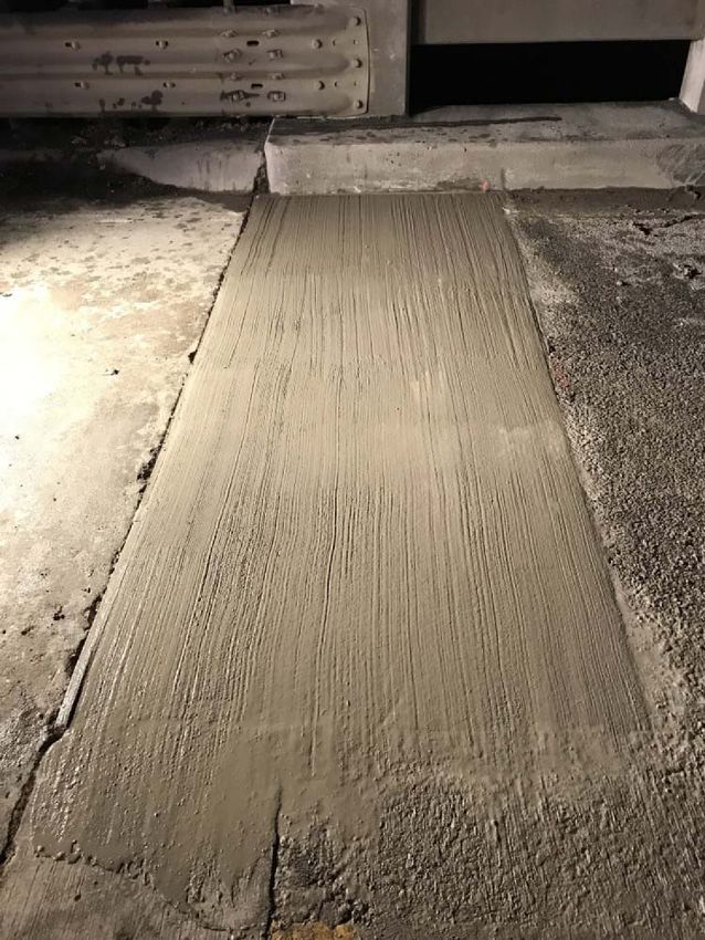
Manual Notice 2021-1
From:             Graham A. Bettis, P.E., Director, Bridge Division

Manual:           Concrete Repair Manual

Effective Date: March 25, 2021

Purpose
    This manual includes step-by-step repair procedures for use on new and existing concrete members cast
    for the Texas Department of Transportation (TxDOT).

Changes

      Revisions to this manual include various editorial changes including: various reference to patch
      revised to repair; incorporated language on following manufacturer's material and procedure
      requirements; incorporated definition of SSD (saturated surface dray); adjusted the duration of
      water blasting requirement to achieve SSD; incorporated detail for concrete repair with mechanical
      anchors, and added steps and photos of a typical full-depth deck repair.

Contact

      Please contact the Bridge Division with comments or questions.

Archives

      Past Manual Notices are available in a PDF archive.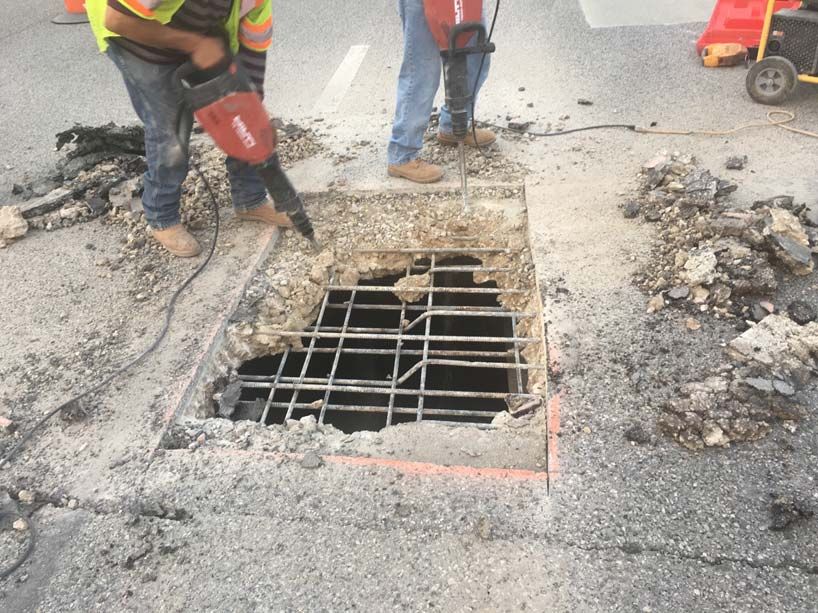
Table of Contents

Chapter 1 — Introduction
         Section 1 — Overview . . . . . . . . . . . . . . . . . . . . . . . . . . . . . . . . . . . . . . . . . . . . . . . . . . . . . . 1-2
               Section 2 — Using the Concrete Repair Manual . . . . . . . . . . . . . . . . . . . . . . . . . . . . . . . . . . 1-5
               Section 3 — Standard Specification References to the Concrete Repair Manual . . . . . . . . . 1-6
               Section 4 — Repairs and Repair Manual. . . . . . . . . . . . . . . . . . . . . . . . . . . . . . . . . . . . . . . . 1-7
               Section 5 — Repair Procedure Submission and Approval . . . . . . . . . . . . . . . . . . . . . . . . . . 1-8
               Section 6 — Quality Control/Quality Assurance. . . . . . . . . . . . . . . . . . . . . . . . . . . . . . . . . . 1-9
               Section 7 — Definitions and Abbreviations . . . . . . . . . . . . . . . . . . . . . . . . . . . . . . . . . . . . 1-12

Chapter 2 — Damage Assessment and Repair Types
         Section 1 — Defining Concrete Spalls . . . . . . . . . . . . . . . . . . . . . . . . . . . . . . . . . . . . . . . . . 2-2
          Description. . . . . . . . . . . . . . . . . . . . . . . . . . . . . . . . . . . . . . . . . . . . . . . . . . . . . . . . . . . . . . 2-2
          Notes . . . . . . . . . . . . . . . . . . . . . . . . . . . . . . . . . . . . . . . . . . . . . . . . . . . . . . . . . . . . . . . . . . 2-2
          Spall Categories . . . . . . . . . . . . . . . . . . . . . . . . . . . . . . . . . . . . . . . . . . . . . . . . . . . . . . . . . . 2-2
          Selecting an Appropriate Repair Procedure . . . . . . . . . . . . . . . . . . . . . . . . . . . . . . . . . . . . 2-3
         Section 2 — Voids Due to Honeycombing . . . . . . . . . . . . . . . . . . . . . . . . . . . . . . . . . . . . . . 2-5
          Description. . . . . . . . . . . . . . . . . . . . . . . . . . . . . . . . . . . . . . . . . . . . . . . . . . . . . . . . . . . . . . 2-5
          Investigating Honeycombed Regions . . . . . . . . . . . . . . . . . . . . . . . . . . . . . . . . . . . . . . . . . 2-5
          Repairing Honeycombed Regions . . . . . . . . . . . . . . . . . . . . . . . . . . . . . . . . . . . . . . . . . . . . 2-5
         Section 3 — Damage over Traffic . . . . . . . . . . . . . . . . . . . . . . . . . . . . . . . . . . . . . . . . . . . . . 2-6
          Description. . . . . . . . . . . . . . . . . . . . . . . . . . . . . . . . . . . . . . . . . . . . . . . . . . . . . . . . . . . . . . 2-6
         Section 4 — Prestressed Concrete Piling. . . . . . . . . . . . . . . . . . . . . . . . . . . . . . . . . . . . . . . . 2-7
          Description. . . . . . . . . . . . . . . . . . . . . . . . . . . . . . . . . . . . . . . . . . . . . . . . . . . . . . . . . . . . . . 2-7
          Reference . . . . . . . . . . . . . . . . . . . . . . . . . . . . . . . . . . . . . . . . . . . . . . . . . . . . . . . . . . . . . . . 2-7
          Notes . . . . . . . . . . . . . . . . . . . . . . . . . . . . . . . . . . . . . . . . . . . . . . . . . . . . . . . . . . . . . . . . . . 2-7
          Damage Prior to Driving (e.g. in the Fabrication Yard) . . . . . . . . . . . . . . . . . . . . . . . . . . . 2-7
          Damage During Driving . . . . . . . . . . . . . . . . . . . . . . . . . . . . . . . . . . . . . . . . . . . . . . . . . . . 2-8
          Lifting Strands . . . . . . . . . . . . . . . . . . . . . . . . . . . . . . . . . . . . . . . . . . . . . . . . . . . . . . . . . . . 2-9
         Section 5 — Taking Cores and Patching Core Holes. . . . . . . . . . . . . . . . . . . . . . . . . . . 2-10
          Description. . . . . . . . . . . . . . . . . . . . . . . . . . . . . . . . . . . . . . . . . . . . . . . . . . . . . . . . . . . . . 2-10
          Selection Criteria . . . . . . . . . . . . . . . . . . . . . . . . . . . . . . . . . . . . . . . . . . . . . . . . . . . . . . . . 2-10
          Taking Cores to Check Compressive Strength . . . . . . . . . . . . . . . . . . . . . . . . . . . . . . . . . 2-10
          Taking Cores to Investigate Specific Defects . . . . . . . . . . . . . . . . . . . . . . . . . . . . . . . . . . 2-10
          Marking Cores . . . . . . . . . . . . . . . . . . . . . . . . . . . . . . . . . . . . . . . . . . . . . . . . . . . . . . . . . . 2-10
          Patching Core Holes . . . . . . . . . . . . . . . . . . . . . . . . . . . . . . . . . . . . . . . . . . . . . . . . . . . . 2-11
         Section 6 — Trimming or Cutting Prestressed Concrete Girder Ends . . . . . . . . . . . . . . . . 2-12
          Description. . . . . . . . . . . . . . . . . . . . . . . . . . . . . . . . . . . . . . . . . . . . . . . . . . . . . . . . . . . . . 2-12

Concrete Repair Manual                                                     i                                                       TxDOT 3/2021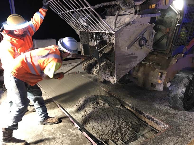
Provisions for Acceptance . . . . . . . . . . . . . . . . . . . . . . . . . . . . . . . . . . . . . . . . . . . . . . . . .            2-12
               Repair Procedure . . . . . . . . . . . . . . . . . . . . . . . . . . . . . . . . . . . . . . . . . . . . . . . . . . . . . . . .       2-13
              Section 7 — Recessing Prestressed Strands . . . . . . . . . . . . . . . . . . . . . . . . . . . . . . . . . . . .                       2-14
               Description. . . . . . . . . . . . . . . . . . . . . . . . . . . . . . . . . . . . . . . . . . . . . . . . . . . . . . . . . . . . .   2-14
               Repair Procedure . . . . . . . . . . . . . . . . . . . . . . . . . . . . . . . . . . . . . . . . . . . . . . . . . . . . . . . .       2-14
              Section 8 — Rail Damage Due to Vehicular Impact . . . . . . . . . . . . . . . . . . . . . . . . . . . . . .                             2-15
               Description. . . . . . . . . . . . . . . . . . . . . . . . . . . . . . . . . . . . . . . . . . . . . . . . . . . . . . . . . . . . .   2-15
               Assessment . . . . . . . . . . . . . . . . . . . . . . . . . . . . . . . . . . . . . . . . . . . . . . . . . . . . . . . . . . . .     2-15
               Repair Procedure . . . . . . . . . . . . . . . . . . . . . . . . . . . . . . . . . . . . . . . . . . . . . . . . . . . . . . . .       2-15

Chapter 3 — Repair Materials and Procedures
         Section 1 — Minor Spall Repair . . . . . . . . . . . . . . . . . . . . . . . . . . . . . . . . . . . . . . . . . . . . . . 3-2
          Description. . . . . . . . . . . . . . . . . . . . . . . . . . . . . . . . . . . . . . . . . . . . . . . . . . . . . . . . . . . . . . 3-2
          Material . . . . . . . . . . . . . . . . . . . . . . . . . . . . . . . . . . . . . . . . . . . . . . . . . . . . . . . . . . . . . . . . 3-2
          Repair Procedure . . . . . . . . . . . . . . . . . . . . . . . . . . . . . . . . . . . . . . . . . . . . . . . . . . . . . . . . . 3-3
          Commentary . . . . . . . . . . . . . . . . . . . . . . . . . . . . . . . . . . . . . . . . . . . . . . . . . . . . . . . . . . . . 3-5
         Section 2 — Intermediate Spall Repair . . . . . . . . . . . . . . . . . . . . . . . . . . . . . . . . . . . . . . . . . 3-6
          Description. . . . . . . . . . . . . . . . . . . . . . . . . . . . . . . . . . . . . . . . . . . . . . . . . . . . . . . . . . . . . . 3-6
          Material . . . . . . . . . . . . . . . . . . . . . . . . . . . . . . . . . . . . . . . . . . . . . . . . . . . . . . . . . . . . . . . . 3-6
          Repair Procedure . . . . . . . . . . . . . . . . . . . . . . . . . . . . . . . . . . . . . . . . . . . . . . . . . . . . . . . . . 3-7
          Commentary . . . . . . . . . . . . . . . . . . . . . . . . . . . . . . . . . . . . . . . . . . . . . . . . . . . . . . . . . . . 3-17
         Section 3 — Major Spall Repair and Concrete Replacement . . . . . . . . . . . . . . . . . . . . . . . 3-18
          Description. . . . . . . . . . . . . . . . . . . . . . . . . . . . . . . . . . . . . . . . . . . . . . . . . . . . . . . . . . . . . 3-18
          Material . . . . . . . . . . . . . . . . . . . . . . . . . . . . . . . . . . . . . . . . . . . . . . . . . . . . . . . . . . . . . . . 3-18
          Repair Procedure . . . . . . . . . . . . . . . . . . . . . . . . . . . . . . . . . . . . . . . . . . . . . . . . . . . . . . . . 3-18
          Commentary . . . . . . . . . . . . . . . . . . . . . . . . . . . . . . . . . . . . . . . . . . . . . . . . . . . . . . . . . . . 3-22
         Section 4 — Bridge Deck Repair. . . . . . . . . . . . . . . . . . . . . . . . . . . . . . . . . . . . . . . . . . . . . 3-23
          Description. . . . . . . . . . . . . . . . . . . . . . . . . . . . . . . . . . . . . . . . . . . . . . . . . . . . . . . . . . . . . 3-23
          Selecting an Appropriate Repair Material . . . . . . . . . . . . . . . . . . . . . . . . . . . . . . . . . . . . . 3-24
          Repair Procedure . . . . . . . . . . . . . . . . . . . . . . . . . . . . . . . . . . . . . . . . . . . . . . . . . . . . . . . . 3-24
          Commentary . . . . . . . . . . . . . . . . . . . . . . . . . . . . . . . . . . . . . . . . . . . . . . . . . . . . . . . . . . . 3-32
         Section 5 — Crack Repair – Pressure-Injected Epoxy . . . . . . . . . . . . . . . . . . . . . . . . . . . . 3-34
          Description. . . . . . . . . . . . . . . . . . . . . . . . . . . . . . . . . . . . . . . . . . . . . . . . . . . . . . . . . . . . . 3-34
          Material . . . . . . . . . . . . . . . . . . . . . . . . . . . . . . . . . . . . . . . . . . . . . . . . . . . . . . . . . . . . . . . 3-34
          Repair Procedure . . . . . . . . . . . . . . . . . . . . . . . . . . . . . . . . . . . . . . . . . . . . . . . . . . . . . . . . 3-34
          Commentary . . . . . . . . . . . . . . . . . . . . . . . . . . . . . . . . . . . . . . . . . . . . . . . . . . . . . . . . . . . 3-36
         Section 6 — Crack Repair – Gravity-Fed Sealant . . . . . . . . . . . . . . . . . . . . . . . . . . . . . . . . 3-37
          Description. . . . . . . . . . . . . . . . . . . . . . . . . . . . . . . . . . . . . . . . . . . . . . . . . . . . . . . . . . . . . 3-37
          Material . . . . . . . . . . . . . . . . . . . . . . . . . . . . . . . . . . . . . . . . . . . . . . . . . . . . . . . . . . . . . . . 3-37

Concrete Repair Manual                                                     ii                                                         TxDOT 3/2021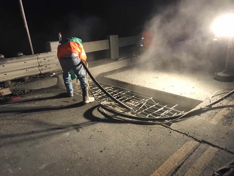
Repair Procedure . . . . . . . . . . . . . . . . . . . . . . . . . . . . . . . . . . . . . . . . . . . . . . . . . . . . . . . .       3-37
           Commentary . . . . . . . . . . . . . . . . . . . . . . . . . . . . . . . . . . . . . . . . . . . . . . . . . . . . . . . . . . .       3-38
          Section 7 — Crack Repair – Surface Sealing . . . . . . . . . . . . . . . . . . . . . . . . . . . . . . . . . . .                        3-39
           Description. . . . . . . . . . . . . . . . . . . . . . . . . . . . . . . . . . . . . . . . . . . . . . . . . . . . . . . . . . . . .   3-39
           Method 1: Rout-and-Seal Cracks. . . . . . . . . . . . . . . . . . . . . . . . . . . . . . . . . . . . . . . . . . . .                  3-39
           Method 2: Surface Sealing. . . . . . . . . . . . . . . . . . . . . . . . . . . . . . . . . . . . . . . . . . . . . . . . .             3-39

Concrete Repair Manual                                                 iii                                                        TxDOT 3/2021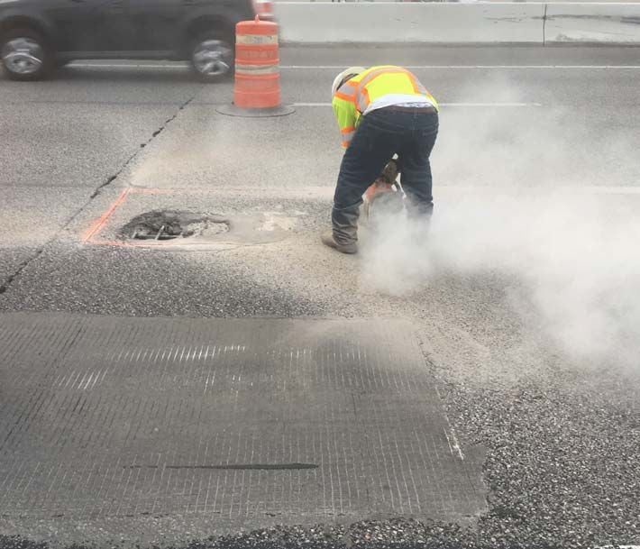
Chapter 1 — Introduction

Contents:
     Section 1 — Overview
     Section 2 — Using the Concrete Repair Manual
     Section 3 — Standard Specification References to the Concrete Repair Manual
     Section 4 — Repairs and Repair Manual
     Section 5 — Repair Procedure Submission and Approval
     Section 6 — Quality Control/Quality Assurance
     Section 7 — Definitions and Abbreviations

Concrete Repair Manual                           1-1                               TxDOT 03/2021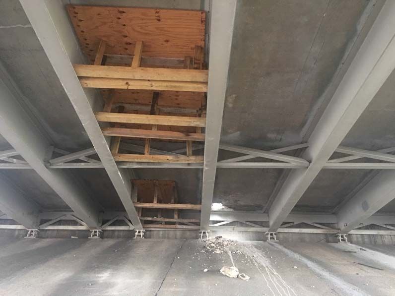
Chapter 1 — Introduction                                                                       Section 1 — Overview

                                         Section 1 — Overview
      This manual includes step-by-step repair procedures for use on existing and new concrete members
      cast for the Texas Department of Transportation (TxDOT). It includes a comprehensive list of com-
      mon concrete distresses and repair methods. The methods adhere to industry standards and the
      provisions from applicable documents by the American Concrete Institute (ACI) and American
      Society for Testing and Materials (ASTM). This manual was developed in collaboration with vari-
      ous repair material manufacturers to ensure that the procedures meet common proprietary
      requirements.

      In general, repairs to TxDOT concrete structures should be implemented in accordance with the
      methods outlined in this manual. However, unusual circumstances occasionally arise. Engineers
      may determine that methods differing from those outlined here are more appropriate in those
      circumstances.

      Updates to the manual are summarized in the following table.

                                    Table 1-1: Manual Revision History

          Version     Publication Date                         Summary of Changes

      2015-1         April 2015          New manual.

      2017-1         January 2017        Revision adding manual revision history to Chapter 1; revision
                                         breaking Chapter 1 into seven sections with no changes to content;
                                         revision adding Section 8, discussing rail damage due to vehicular
                                         impact, to Chapter 2; revisions for consistency with current DMS-
                                         4655; revised maximum application for neat product to 2"; various
                                         revisions to Chapter 3, Section 4, “Bridge Deck Repair” and
                                         Section 6, “Crack Repair – Gravity-Fed Epoxy” for improved
                                         performance of repairs; minor formatting and editorial revisions in
                                         various sections.

Concrete Repair Manual                                 1-2                                            TxDOT 03/2021
Chapter 1 — Introduction Section 1 — Overview
Table 1-1: Manual Revision History
Version Publication Date Summary of Changes
2019-1 January 2019 Various editorial revisions including:
Reference to CST revised to MTD
Reference to epoxy anchors revised to adhesive anchors.
Various references to patch revised to repair.
Ch 1, Section 6:
Incorporated visual and non-destructive evaluation of repair
material as part of Contractor's Responsibilities (QC).
Ch 2 Section 4:
Added procedure to recess and coat lifting strands on pre-
stressed piling after installation of piling.
Ch 2, Section 8:
Referenced Item 445, "Galvanizing" for repair material to
galvanized rail components.
Added language that tests on new railing adhesive anchorage
may be required by the Engineer.
Ch 3, Section 1
Incorporated storage, temperature, humidity controls, and
document controls to ensure material quality.
Ch 3, Section 2:
Incorporated typical repair detail and photos showing steps for
typical intermediate spall repair.
Incorporated language for temperature controls for mixing and
using chilled water.
Added inspection prior to finishing
Ch 3, Section 3:
Added inspection prior to finishing
Ch 3, Section 6:
Gravity-Fed Epoxy revised to Gravity-Fed Sealant to include
other acceptable sealants.
Incorporated language to follow product specifications for
maximum working time.
Concrete Repair Manual 1-3 TxDOT 03/2021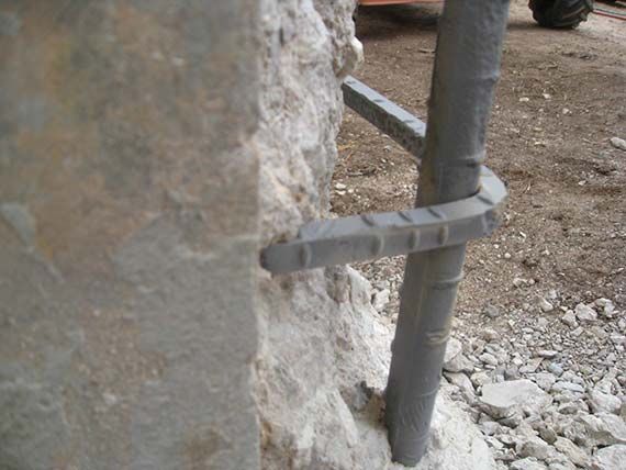
Chapter 1 — Introduction Section 1 — Overview
Table 1-1: Manual Revision History
Version Publication Date Summary of Changes
2021-1 February 2021 Various editorial revisions including:
Various references to patch revised to
repair.
Ch 1, Section 6:
Incorporated language about agreement on
location of nondestructive testing.
Ch 2, Section 3:
Incorporated that repair plans need to be
sealed and signed by professional
engineer.
Ch 2, Section 5:
Removed discussion on taking cores to
investigate material problems
Included requirement of marking top and
bottom surface of full depth cores
Ch 3, Section 1
Incorporated language about following man-
ufacturer's material and procedure
requirement.
Ch 3, Section 2:
Removed ‘other approved techniques’ to
remove rust from exposed steel surfaces.
Incorporated detail for concrete repair
with mechanical anchors.
Included definition of SSD (saturated sur-
face dry)
Adjusted the duration of water blasting to
at least 15 minutes to achieve SSD.
Ch 3, Section 3:
Removed 'other approved techniques' to
remove rust from exposed steel surfaces.
Ch 3, Section 4:
Adjusted the duration of water blasting to
at least 15 minutes to achieve SSD
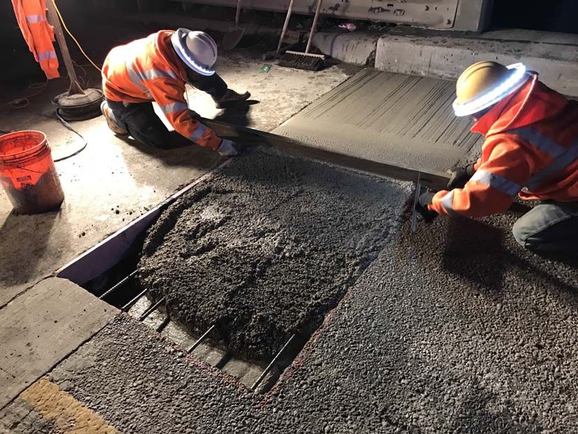
Added steps and photos of typical full-
depth deck repair.
Removed “other approved techniques” to
remove rust from exposed steel surfaces.
Concrete Repair Manual 1-4 TxDOT 03/2021
Chapter 1 — Introduction                                      Section 2 — Using the Concrete Repair Manual

                         Section 2 — Using the Concrete Repair Manual
      When developing repair or rehabilitation plans, the Engineer should specifically include which
      sections of this manual will be enforced. Chapter 2 includes information on assessing damage,
      distress limits, and common types of concrete repair. Chapter 3 includes information on various
      repair materials and procedures for implementation.

      Typically concrete repair work will include categorizing the type of distress as outlined in Chapter
      2 and selecting a type of repair material from Chapter 3. In some cases, the material section
      includes enough information that choosing a corresponding type of repair is not necessary. For
      instance, the sections on crack repair do not require that corresponding repair types be selected

      Each section in this manual is written as a stand-alone document, and individual sections contain all
      necessary information on material selection and application. It is not necessary to read the manual
      from start to finish. Rather, the intention is that Inspectors and Contractors will need only to
      reference the applicable section or sections. The sections are kept as concise as possible since they
      are intended for field use.

      This manual does not address post-tension strand, duct, or anchorage repairs. Repairs or defects
      associated with post-tension work should be addressed by the Bridge Division Construction &
      Maintenance Branch on a case-by-case basis.

Concrete Repair Manual                              1-5                                     TxDOT 03/2021
Chapter 1 — Introduction Section 3 — Standard Specification References to the
Concrete Repair Manual
Section 3 — Standard Specification References to the Concrete Repair Manual
The Concrete Repair Manual is referenced in several 2014 Standard Specification Items. This
section includes a list of each of those references, along with the corresponding Section to reference
within this Manual.
Standard Specification References
Spec Item Item Title Spec Reference Repair Manual Reference
409 Prestressed Concrete 3.1 (Defects and Refer to Section 2.4 for limits and repair
Piling Breakage) procedures when assessing damage to pre-
stressed concrete piling.
420 Concrete Substructures 4.13 (Ordinary Surface Spalls are defined per Section 2.1, and
Finish) repaired (based on severity) per Section
3.1, 3.2, or 3.3. Most spalls in this category
will be defined as minor and repaired per
Section 3.1.
424 Precast Concrete Struc- 4.3 (Workmanship) Recess prestressed strands per Section 2.7.
tural Members
(Fabrication) 4.3.1 (Defects and This item covers damage or surface defects
Breakage) that occur during fabrication, handling,
storage, hauling, or erection of precast
concrete members. Any of the sections in
this manual could apply depending on the
situation.
429 Concrete Structure 2 (Materials) Severity of the unsound, delaminated, or
Repair 3 (Construction spalled concrete is defined per Section 2.1.
Methods) After defining, select materials and imple-
ment repair per Section 3.1 (Minor), 3.2
(Intermediate), or 3.3 (Major).
780 Concrete Crack Repair 2 (Materials) Select materials and perform repair work in
3 (Construction accordance with the applicable section in
Methods) this manual. Section 3.5 covers pressure-
injected epoxy, 3.6 covers gravity-fed seal-
ant, and 3.7 covers both routing and sealing
and surface sealing.
788 Concrete Beam Repair 2 (Work Methods) Concrete Beam Repair is a plan-specific
item. Provide materials and perform work
in accordance with the applicable sections
of this Manual and as defined in the project
plans.
Concrete Repair Manual 1-6 TxDOT 03/2021Chapter 1 — Introduction Section 4 — Repairs and Repair Manual
Section 4 — Repairs and Repair Manual
It is critical that repair crews use appropriate repair materials and installation methods. Even the
best materials will not work effectively unless each aspect of the repair work is considered. Proper
proportioning, mixing, surface preparation, application, and curing are all vital to the long-term
success of a repair.
TxDOT maintains Departmental Material Specifications and corresponding preapproved Material
Producer Lists for most of the materials outlined in the manual. It is vital that Engineers,
Inspectors, and Contractors select and use only preapproved materials when applicable. The
Engineer may select or Contractors may propose to use material not included on an MPL if it will
provide for the best repair in a specific application. The Engineer will review such requests from
the Contractor on a case-by-case basis, but in almost all cases a preapproved material should be
selected.
Notify the Engineer before proceeding with the repairs if there are discrepancies between TxDOT’s
requirements and industry standards or manufacturers’ instructions. Maintain up to date copies of
the manufacturers’ technical literature to ensure the proper procedures are followed.
Concrete Repair Manual 1-7 TxDOT 03/2021Chapter 1 — Introduction Section 5 — Repair Procedure Submission and
Approval
Section 5 — Repair Procedure Submission and Approval
When the Engineer prepares repair or rehabilitation plans that include reference to this manual, the
Contractor must prepare and submit formal procedures outlining repair plans and which proprietary
materials they plan to utilize. The Engineer must approve in writing any procedures that differ from
those in this manual or materials that are not included in one of TxDOT’s MPLs.
For damage that occurs in precast concrete fabrication yards or on construction sites in which
Contractor is required to prepare a Nonconformance Report or Request for Information, the
Contractor should propose repair methods and materials outlined in this manual. Contractors may
also propose to use a procedure that differs from those outlined in this manual, in which case
TxDOT will consider on a case-by-case basis.
For minor defects in which the Engineer is not preparing repair documents and the Contractor
is not issuing a Nonconformance Report or Request for Information, the Contractor and Inspectors
should work collaboratively to determine an appropriate repair solution and then follow the appli-
cable sections from this manual. Documentation of this communication should be retained in the
project files.
Concrete Repair Manual 1-8 TxDOT 03/2021Chapter 1 — Introduction Section 6 — Quality Control/Quality Assurance
Section 6 — Quality Control/Quality Assurance
In addition to providing step-by-step procedures for Contractors and Fabricators, this manual is
also meant to provide Quality Control (Contractor) and Quality Assurance (Owner) inspectors with
the knowledge needed to ensure that appropriate repair solutions are selected and implemented.
Each procedure in Chapter 3 of this manual includes detailed instructions on each individual facet
of repair solutions.
Proper attention to and implementation of each step in the repair process is critical to successful
application. The first step is ensuring that the contractor is using approved materials. Correct
proportioning and mixing is also critical. A common mistake is for Contractors to “eyeball” or
guess at proper proportions when using multi-part mixes. Inspectors should verify that Contractors
are measuring, either by volume or weight, all individual components prior to mixing. In almost all
cases the Contractor should utilize an acceptable form of mechanical mixing; hand mixing is not
acceptable. It is not possible to put a sufficient amount of energy into mixing when doing so using a
shovel, trowel, or by hand. In small applications a small “jiffy” type paddle and mixer are often
sufficient. When using larger quantities of cementitious repair material a mortar or volumetric
mixer is more appropriate.
Application varies significantly with repair type and material. Refer to the applicable section in
Chapter 3.
Another frequent problem leading to premature failure of repairs, especially cementitious
materials, is inadequate curing. Improper curing often leads to cracking very early in the life of the
repair. The best (and easiest) curing method is to leave the forms in place when using form-and-
pour applications. In those cases only a small amount of moist curing is required in the small areas
used to place the concrete. Ponding is also an excellent method of curing but is typically
impractical in most repair scenarios. Many manufacturers include instructions for application of
curing membranes. However, continuous moist curing is typically preferable to curing membranes.
When using wet mats it is imperative that the mats be kept moist during the entire curing interval.
In cases where membrane curing is approved, the Contractor must use material that is preapproved
by TxDOT and is recommended for use by the repair material manufacturer.
Since curing requirements vary significantly depending on the type of material and the manufac-
turer, it is important that curing methods adhere to the technical product literature for the specific
material being utilized. As noted above, moist curing is the preferred method for most cementitious
repair materials. However, moist curing can actually harm some repair materials, such as
those that contain magnesium phosphate. Again, the Contractor must adhere to the requirements for
the specific material being applied.
Contractor’s Responsibilities (QC):
Concrete Repair Manual 1-9 TxDOT 03/2021Chapter 1 — Introduction Section 6 — Quality Control/Quality Assurance
It is the Contractor’s responsibility to use repair materials specified in the Contract Documents
and this manual. For materials in which there are lists of available through TxDOT’s MPL, the
Contractor should only use products that have been preapproved. Any deviation from the
originally proposed and approved materials must be approved by the Engineer in writing.
When in doubt, contact the Bridge Division or Materials and Tests Division for guidance on
whether a proposed material is acceptable.
Shelf life of repair materials is critical, store materials on jobsite
according to material manufacturer’s requirements, preventing direct exposure to sunlight and
moisture. Materials exceeding their shelf life shall not be used.
When required by the Contract, perform a trial repair or mockup to demonstrate acceptable
performance and installation methods.
Ultimately, quality is the Contractor’s responsibility. If the Contractor feels that any of the
procedures outlined in this manual or in the contract plans could lead to unacceptable
performance, they must inform the Engineer of those concerns in writing prior to commencing
work. In such cases, the Engineer will work collaboratively with the Contractor to come to an
agreeable solution.
Confirm that repair material performance is acceptable through visual observations and nonde-
structive testing of all repaired locations. Repair material should not exhibit cracking. One of
the easiest and most effective tests is to sound the repair material using firm (but not destruc-
tive) blows with a hammer. When repair material has debonded from the substrate there is
generally a distinctive hollow sound when the material is struck. Defective repair material
must be removed and replaced at no extra costs to the Department.
Owner’s Responsibilities (QA):
Check materials to ensure that they are appropriate for the given application. Material should
either be on one of TxDOT’s preapproved lists or approved by the Engineer prior to use.
Ensure that the Contractor is following the procedures outlined in this manual and as shown on
the plans for material selection, preparation, implementation, curing, and any other steps
crucial to the performance of the concrete repair. Procedures may need to be altered for
varying weather conditions (excessive heat or cold, rain, high wind, etc.).
Verify that all damaged material has been removed and that the remaining surface is clean and
sound before the Contractor proceeds with repair material installation.
Confirm that repair material performance is acceptable through visual observations and
nondestructive testing. See Contractor's Responsibilities (QC) for acceptance criteria. QA may
be performed jointly with the contractor's QC or separately at the discretion of the Engineer.
In some cases, the Contractor may opt to perform nondestructive or destructive testing when
there is a question about whether a repair is performing adequately. Often such testing will
involve taking cores for petrographic analysis. Though a Contactor may use an independent
consultant or lab for performing forensic or petrographic investigations, ultimately TxDOT
Concrete Repair Manual 1-10 TxDOT 03/2021Chapter 1 — Introduction Section 6 — Quality Control/Quality Assurance
will decide whether a repair is acceptable. The location of the destructive
testing should be agreed upon by the owner and the Contractor.
Concrete Repair Manual 1-11 TxDOT 03/2021Chapter 1 — Introduction Section 7 — Definitions and Abbreviations
Section 7 — Definitions and Abbreviations
The terms “Engineer,” “Inspector,” “Contractor,” and “Fabricator” are used regularly throughout
this manual. “Engineer” typically refers to the Engineer of Record that signed and sealed the repair
plans, the Area Engineer or the Area Engineer’s authorized representative where the work is being
performed, or in the case of precast fabrication one of the licensed Professional Engineers at
TxDOT Materials and Tests Division Headquarters in Austin. “Inspector” refers to the person,
usually a Department employee, assigned by the Engineer to check compliance with the Contract.
“Contractor” refers to the entity responsible for implementing the repair work. “Fabricator” refers
to a manufacturer that produces precast concrete structures for TxDOT. When not specifically
stated, requirements for Contractors also apply to Fabricators.
The following abbreviations are used in the manual:
CFRP: Carbon Fiber Reinforced Polymer
MTD: TxDOT Materials and Test Division
DMS: Departmental Material Specification
MPL: Material Producer List
NCR: Nonconformance Report (typically prepared by Precast Fabricators)
QA: Quality Assurance
QC: Quality Control
RPM: Revolutions per Minute
SSD: Saturated Surface-Dry
NDE: Nondestructive Evaluation
Concrete Repair Manual 1-12 TxDOT 03/2021Chapter 2 — Damage Assessment and Repair Types
Contents:
Section 1 — Defining Concrete Spalls
Section 2 — Voids Due to Honeycombing
Section 3 — Damage over Traffic
Section 4 — Prestressed Concrete Piling
Section 5 — Taking Cores and Patching Core Holes
Section 6 — Trimming or Cutting Prestressed Concrete Girder Ends
Section 7 — Recessing Prestressed Strands
Section 8 — Rail Damage Due to Vehicular Impact
Concrete Repair Manual 2-1 TxDOT 03/2021Chapter 2 — Damage Assessment and Repair Types Section 1 — Defining Concrete Spalls
Section 1 — Defining Concrete Spalls
Description
Spalls are categorized based on severity of damage per the definitions in this Section. Once a spall
has been categorized, then an appropriate repair material and installation procedure can be selected.
Reference: TxDOT Standard Specification Item 429, “Concrete Structure Repair.”
Notes
Based on severity, spalls can be categorized as minor, intermediate, or major. Appropriate repair
materials and methods differ significantly depending on the spall depth, size (area), cause(s) and
configuration (horizontal, vertical, or overhead). The guidelines in this section help define various
spall types. These are general definitions; depending on the circumstances, the Engineer may
define spall severity differently than these definitions, on a case-by-case basis.
This section does not apply to spalls in the riding surfaces of bridge decks. Refer to the Chapter 3
sections on Bridge Deck Repair when addressing such damage.
Spall Categories
Minor Spall:
Damage is less than 1 inch deep and it covers an area less than 12 square inches. However,
if the majority (more than 50%) of a reinforcing bar or strand circumference is exposed
due to inadequate cover then the spall would be classified as Intermediate even if it is less
than 1" deep.
The Inspector may elect to designate repairs that cover areas larger than 12 square
inches as minor depending on the location and extent of the damage.
A deeper spall (2" maximum) can be categorized as minor as long as it does not progress
beyond the outer layer of reinforcement.
Intermediate Spall:
The damage exposes a majority (more than 50%) of the outer cage of reinforcing bar or
strand circumference, or the damage is greater than 2" deep.
The maximum depth of an intermediate spall is 6 inches.
No significant stresses are likely to develop in or immediately around the repair mate-
rial due to service loads.
Major Spall:
Damage extends well beyond the outer layer of reinforcement.
Concrete Repair Manual 2-2 TxDOT 03/2021Chapter 2 — Damage Assessment and Repair Types Section 1 — Defining Concrete Spalls
Significant stresses are likely to develop in or immediately around the repair material
due to service loads.
Selecting an Appropriate Repair Procedure
Beyond categorization of spalls, repair procedures depend on location to be repaired and volume of
work. The following is only a brief overview of repairs. See Chapter 3 for detailed discussion on
repair materials and procedure.
Minor Spall:
Regardless of configuration (vertical, overhead, or horizontal), the best repair method for
minor spalls is typically neat epoxy or epoxy mortar. Epoxy that is formulated for concrete
repair has very tenacious bond and performs well in thin applications.
Excavating the concrete to expose all corroded sections of the bar is an effective
way to mitigate corrosion, but that typically requires the removal of sound material.
Such measures are usually unnecessary unless the minor spalling is occurring over a large
area.
Applying epoxy over thin spalls in which a small amount of steel is exposed will not
typically stop corrosion. However, it provides an excellent waterproof barrier and can
significantly slow down the rate of corrosion if properly applied.
Building up thin spalls with epoxy mortar is generally an aesthetic decision. Mortar should
not be applied if the repair will occur over vehicular or pedestrian traffic. In those cases
only neat epoxy should be applied.
Intermediate Spall:
Proprietary, bagged concrete repair materials are typically used to repair intermediate
spalls. Use only preapproved materials meeting the requirements of DMS-4655, “Con-
crete Repair Materials.”
A common mistake when choosing bagged cementitious concrete repair materials is to
select those with compressive strengths far higher than needed. Materials with lower com-
pressive strengths typically perform better since they also have a lower modulus of
elasticity, and therefore greater ductility. For intermediate spalls it is typically desirable
not to redistribute loads into the repair material. Limiting compressive strength and
modulus of elasticity are the best ways of achieving that.
Vertical and Overhead Repairs:
In most cases a Contractor will opt to use a trowel-applied repair material in vertical
and overhead applications. The maximum lift thickness of trowel-applied materials is
2 inches or the maximum permitted by the repair material supplier, whichever is less.
In deeper applications the Contractor may propose to repair using pneumatically
applied cementitious material, in which case they should follow the provisions set
forth in Item 431. Pneumatically placed concrete is not addressed in this manual. The
Concrete Repair Manual 2-3 TxDOT 03/2021Chapter 2 — Damage Assessment and Repair Types Section 1 — Defining Concrete Spalls
Engineer must approve use of pneumatically placed concrete in lieu of the repair
methods outlined in this manual.
The Contractor may opt to use form-and-poured bagged material or batched concrete,
which is often a better option since it can be extended with coarse aggregate. Most
trowel-applied materials do not include coarse aggregate, which can lead to drying
shrinkage cracking if not applied or cured properly.
Horizontal Repairs: Form-and-pour materials are typically the best option in horizontal
applications because they can be extended with coarse aggregate, which significantly reduces
the potential for shrinkage cracking.
Precast Concrete Production Yards: Batched concrete is readily available in precast concrete
plants. Therefore, fabricators should typically use batched concrete (same mix design) as that
used to fabricate the damaged member, even when the spall is classified as intermediate.
Major Spall:
Major spalls typically involve deep repairs to members in which capacity has been
reduced as a result of damage and deterioration. The repair is meant to restore
capacity of the damaged member. The best option in such applications is to use batched
concrete with properties similar to the parent material.
When the mix design is unknown, the Engineer and Contractor should select an approved
concrete mix that meets the requirements of the anticipated service loads.
In smaller applications it is often not practical to specify batched concrete when
rehabilitating or repairing existing structures. The Engineer should determine when a
preapproved bagged material is more appropriate and offer that as an alternative to
batched concrete.
In some cases, additional anchoring may be required as
directed by the repair details.
Concrete Repair Manual 2-4 TxDOT 03/2021Chapter 2 — Damage Assessment and Repair Types Section 2 — Voids Due to Honeycombing
Section 2 — Voids Due to Honeycombing
Description
Honeycombing in concrete members can result from either of the following:
Forms not being sufficiently secured or tight, allowing mortar to leak out during casting
operations. The mortar leakage can lead to voids between coarse aggregates.
Insufficient consolidation due to poor workability of concrete mixes or inade-
quate vibration.
Investigating Honeycombed Regions
The biggest cause for concern when voids occur on the exterior portions of members is that
additional, unseen defects could exist on the interior portions. Honeycombing due to lack of proper
consolidation is of particular concern, especially in the portions of precast concrete members that
are highly congested with prestressing strands and mild reinforcement.
Prior to considering repair options, explore the voids to check for additional damage. The areas
around the voids should be chipped to sound, undamaged concrete. However, do not chip out
concrete around prestressed strands before discussing with the Engineer.
Occasionally Contractors ask to use Nondestructive Evaluation (NDE) to investigate the severity of
honeycombing when it appears to be severe and the Engineer is considering rejection. Most of the
available technology (e.g. Impact Echo and Pulse Velocity) cannot effectively show whether small
voids exist along congested prestressing strands or mild reinforcement. Although the Contractor
may propose to use NDE, it is up to the Engineer to determine whether it is acceptable. Generally
NDE requires destructive verification testing, which is oftentimes not an option in highly congested
concrete, such as the bottom flanges of prestressed girders.
Repairing Honeycombed Regions
After the honeycombed regions have been removed, the damaged area should be evaluated and
defined per Section 1 of Chapter 2 unless the damage is too severe to consider acceptance of the
member. An appropriate repair material and method can be selected once the damage is categorized
as minor, intermediate, or major.
At a minimum, remove defective material, repair and finish as required in Section 420.4.13 of
the Standard Specifications for Ordinary Surface Finish.
Concrete Repair Manual 2-5 TxDOT 03/2021Chapter 2 — Damage Assessment and Repair Types Section 3 — Damage over Traffic
Section 3 — Damage over Traffic
Description
This section applies to damage that occurs or could occur over vehicular or pedestrian traffic. Dam-
age consists of any spall, delamination, honeycombing, or other unintentional void. The Engineer
will typically require additional measures to help ensure the repair material will not fall into traffic
in the case of a repair failure.
The most frequent damage that occurs over roadways is overhead vehicular impact. In addition to
whatever necessary structural and waterproofing repairs, the Engineer should typically also require
confinement or other acceptable means to prevent spalling or to catch portions of the repair mate-
rial that become detached. Wire netting often works as a temporary solution. More permanent
solutions should be included when the member or members are repaired. In almost all cases the best
option for preventing damaged concrete from falling onto traffic is to confine the repair material
with Carbon Fiber Reinforced Polymer wraps. Perform the CFRP work in accordance with Item
786, “Carbon Fiber Reinforced Polymer.”
In the case of precast concrete fabrication, damage that will occur over traffic may not be
repaired unless approved by the Engineer. When feasible, members should be reassigned or
rotated to move the damage to an area where damage will not occur over traffic in its final configu-
ration. Minor damage may be coated with neat Type VIII epoxy but should not be built up with
repair mortar. When the Engineer does permit more extensive repair, the repair material must be
confined using CFRP or other approved method.
There is no standard repair procedure for repairing damage over traffic. A repair plan
must be signed and sealed by a professional engineer licensed in
Texas. Do not proceed with such repairs without authorization from the Engineer.
Concrete Repair Manual 2-6 TxDOT 03/2021Chapter 2 — Damage Assessment and Repair Types Section 4 — Prestressed Concrete Piling
Section 4 — Prestressed Concrete Piling
Description
This section includes limits and repair procedures when assessing damage to prestressed concrete
piling.
This section also includes a procedure to recess and coat lifting strands after installation of piling.
Reference
Standard Specification Item 409, “Prestressed Concrete Piling.”
Notes
Piling damage is divided into two categories: (1) damage that occurs prior to driving (during
fabrication, handling, storing, or hauling), and (2) damage that occurs during driving operations
(lifting or driving). When assessing damage to exposed portions of prestressed piling in an existing
structure, treat it as a typical concrete substructure element. No special limits apply.
The acceptance and rejection criteria for prestressed piling are more severe than with most other
structural elements because the consequences of a failure are also very severe. Foundation distress
is typically very difficult to remedy and can lead to shortened service life of an entire bridge.
Therefore, damage that could potentially hinder performance or reduce durability will typically
lead to rejection of the piling.
Damage Prior to Driving (e.g. in the Fabrication Yard)
Minor damage.
Only thin spalls may be repaired. The Engineer will determine what constitutes an
acceptable spall, but in general the limits are 1-inch in depth and 6 square inches in area. If
either of those limits is exceeded, or if the damage exposes any reinforcing steel or
prestressing strand, the damage will render the piling unacceptable unless specifically
deemed otherwise by the Engineer.
Smooth out the perimeter of the damaged area to eliminate jagged edges.
Minor spalls deemed acceptable for repair should be cleaned and coated with neat epoxy
in accordance with Section 1 of Chapter 3 of this manual.
Do not build up the spalled areas with repair material other than neat epoxy since it is
likely to debond during driving operations.
Concrete Repair Manual 2-7 TxDOT 03/2021Chapter 2 — Damage Assessment and Repair Types Section 4 — Prestressed Concrete Piling
The Engineer may allow for repair when damage is deeper than 1 inch but does not
progress beyond the outer layer of steel reinforcement. In those cases the damaged areas
should be built up with epoxy mortar and confined by CFRP wrapped completely around
the piling for a distance not less than six inches beyond the damaged area.
Damage to one end.
If one end of a piling is damaged beyond the limits outlined above, but the damage
extends less than 6 inches from the end, then the fabricator or contractor may remove (cut)
up to 6 inches from the end to eliminate the damaged portion.
Clearly mark the altered side as the “Tip End.”
After cutting, recess the prestressing strands 3/8-inch minimum and fill the voids with
epoxy mortar (typical strand end treatment).
Re-form the chamfers after completing the cutting and repairing operations.
Damage to both ends.
There are no standard criteria for acceptance or rejection when both ends of a piling are
damaged, but generally the member will be rejected since it would not be possible to avoid
hammering a damaged end.
Engineer must approve any repairs when damage occurs on both ends of a piling.
Damage During Driving
Horizontal cracks (transverse to longitudinal reinforcement or strand) greater than 1/16 inches
wide.
Piling will be rejected if crack occurs in a portion that will be below ground or water level
after driving.
If crack occurs in a portion that will be above grade or water level, the Contractor may opt
to cut back beyond the crack and rebuild to required elevation.
Horizontal cracks less than 1/16 inches wide.
Inject the cracks with epoxy in accordance with Section 3.7 of this manual.
If cracks develop that will be inaccessible in final configuration, cease driving operations
and repair cracks before continuing.
Vertical or diagonal cracks.
In most cases a piling member will be rejected if vertical or diagonal cracks form during
driving operations.
If the Engineer approves repair of vertical or horizontal cracks, inject with epoxy in
accordance with Section 3.7 of this manual.
Fine hairline cracks (less than 0.006 inches) or surface checks that do not extend to the plane of
the nearest reinforcing steel will not require repair and will not be cause for rejection.
Concrete Repair Manual 2-8 TxDOT 03/2021Chapter 2 — Damage Assessment and Repair Types Section 4 — Prestressed Concrete Piling
Lifting Strands
Recess lifting strands to help prevent corrosion due to exposure to the elements.
Recess the prestressing strands a minimum 3/4-inch using a torch, grinder, or other
approved method. Do not overheat or damage the surrounding concrete.
Abrade the concrete and the end of the steel strand with a needle gun, steel brush, or other
suitable means to ensure that no slag remains on the steel or concrete surfaces.
Coat the inside of the recessed area, including the strand, with 10 mils (minimum) of neat
Type VIII epoxy and repair the recess with epoxy mortar.
Concrete Repair Manual 2-9 TxDOT 03/2021Chapter 2 — Damage Assessment and Repair Types Section 5 — Taking Cores and Patching Core
Holes
Section 5 — Taking Cores and Patching Core Holes
Description
Cores may be taken from concrete members for a variety of reasons, including verification of
compressive strength, investigation of potential concrete material problems (e.g. segregation or
bleeding), or examination of specific defects (e.g. cracks or cold joints). This section covers proper
taking and marking of cores, and patching of the core holes.
Selection Criteria
Select core locations and have them approved by the Engineer. Check fabrication sheets so, cores
are taken with minimum impact to mild reinforcement. Check design sheets or shop drawings to
ensure that cores are not taken through prestressing strands unless specifically approved by the
Engineer. For prestressing strands use GPR and other NDE methods to
locate the strands.
Take four-inch outside diameter cores when feasible. When approved by the Engineer, take smaller
cores in highly congested areas to avoid impact to mild reinforcement or prestressed strands.
Taking Cores to Check Compressive Strength
Take at least two cores from a member if companion cylinders reveal a potential deficiency
in the required 28-day compressive strength.
Evenly space the cores along the member(s) in question. Typically, take the cores through the
webs or sidewalls of prestressed concrete girders.
There can be no mild reinforcement or prestressed strands in the cores if they will be used for
testing compressive strength.
Taking Cores to Investigate Specific Defects
Take cores directly through the problem areas when investigating specific damage or defects. It
typically will not be necessary to take control cores in these types of situations.
If investigating a cold joint, take the sample such that approximately half the core is above the
joint and half is below the joint.
Marking Cores
When cores are not taken from a horizontal surface, draw two arrows on the core locations
BEFORE a core is taken. Point both arrows straight up, and draw them on each side (left and right)
Concrete Repair Manual 2-10 TxDOT 03/2021Chapter 2 — Damage Assessment and Repair Types Section 5 — Taking Cores and Patching Core
Holes
of the core. In most cases the petrographer will need to cut in the vertical orientation, so it is
important that the core be marked such that both sides will indicate the “up” direction after cutting.
After a core has been taken, write additional information on each side (left and right) of the sample.
Include the following information:
Structure No. (existing structure) or CSJ (new construction).
For new construction, name of Prime Contractor if at jobsite or Fabricator if in Precast
Concrete Plant.
Member ID and location.
Core number. Also, take photographs and notes indicating from where in the member the core
was taken and why.
Top and bottom surfaces for full depth cores.
Again, most cores are cut vertically. Write all of the above information on both sides of the core so
each part of the sample can be properly identified if it is cut.
Include a standard TxDOT Form 202 for each set of cores taken from a member. Request that the
TxDOT Inspectors fill out Form 202 as needed so hard copies of the completed forms can be sent
directly with the samples. Also send copies of applicable concrete mix design worksheets, batch
tickets, and strength data with the cores when they are available.
Patching Core Holes
As with all large patches, utilize preapproved bagged cementitious repair material or batched
concrete to patch core holes when feasible. Follow the requirements set forth in the section on
Intermediate Spall Repair for implementing the work.
Concrete Repair Manual 2-11 TxDOT 03/2021Chapter 2 — Damage Assessment and Repair Types Section 6 — Trimming or Cutting Prestressed
Concrete Girder Ends
Section 6 — Trimming or Cutting Prestressed Concrete Girder Ends
Description
This section includes allowances and repair procedures for trimming or cutting the ends of
prestressed concrete I-beams.
Removal of more than 1 inch of a beam end is considered cutting.
Removal of 1 inch or less from a beam end is considered trimming.
Cutting beam ends requires preparation of an NCR from the Fabricator. The TxDOT Inspector
determines whether an NCR is required when a beam end will be trimmed.
NOTE: Standard provisions for cutting beam ends apply to Tx Girders (bulb tees) only. Cutting the
ends of prestressed members other than Tx Girders requires a detailed analysis by a
Professional Engineer and authorization from TxDOT MTD Headquarters or the Bridge
Division. There is no standard repair for such alterations; proposals will be considered on a
case-by-case basis.
Provisions for Acceptance
No more than 12 inches may be removed from either girder end.
If more than 6 inches is removed from a girder end, include in the modification proposal stamped
calculations from a Professional Engineer indicating the viability of the proposed modification.
Calculations must include:
Required moment and shear capacity.
Actual moment capacity of the modified member, obtained using PGSuper or another
acceptable analysis program.
Actual shear capacity.
In most cases equal amounts should be removed from each end if the total length to be cut exceeds
6 inches. However, that would not be a viable solution if a beam end is being cut in order to
eliminate damage or when a beam end contains an anchor slot.
The Area Engineer and MTD Engineer must approve modifications. All parties, including the
Fabricator, Contractor, and Engineer, must agree that trimming will not result in any unacceptable
issues related to deck forming, slab or haunch thickness, camber, or plan profile deck geometry.
The girder must be modified as required for use in its new configuration, including but not limited
to blockouts, inserts, hangers, and bevels.
Concrete Repair Manual 2-12 TxDOT 03/2021Chapter 2 — Damage Assessment and Repair Types Section 6 — Trimming or Cutting Prestressed
Concrete Girder Ends
When the strand pattern differs from the destination design, or if more than 6" is cut off one or both
beam ends, a replacement shop plan for the permanent record must be provided that indicates all
characteristics of the candidate girder that differ from the originally specified girder.
Include dual girder identification by permanently marking the inside face of the girder, clearly
indicating which is the previous girder I.D. and which is the current I.D. Fabricator or Contractor
must send written notification to the Area Engineer informing them of the circumstances of the
dual marked girder for their information and records.
Repair Procedure
After the beam has been trimmed or cut, re-measure the member (length, skew, and batter) to
ensure that the altered dimensions are acceptable.
Once the dimensions have been checked and found to be acceptable, remove all vertical
reinforcement that has less than 3/4-inch concrete cover. Recess longitudinal reinforcing steel and
prestressing strands approximately 3/8-inch.
Locate the steel using shop drawings, exploratory drilling, and whatever other means is
necessary to ensure that all reinforcement with inadequate concrete cover is identified.
Remove the steel using a torch or other approved method. Do not overheat or damage the
surrounding concrete and steel that will remain in place.
If steel is removed using a torch, abrade the steel and concrete surfaces with a needle gun, steel
brush, or other suitable means to ensure that no slag remains.
Apply a silane penetrating sealer and neat Type VIII epoxy to every portion of the member that was
trimmed or cut. Wait at least 48 hours after applying the penetrating sealer before applying neat
epoxy. Do not extend the neat epoxy material with sand except to fill in the voids where the steel
has been recessed or removed.
Concrete Repair Manual 2-13 TxDOT 03/2021Chapter 2 — Damage Assessment and Repair Types Section 7 — Recessing Prestressed Strands
Section 7 — Recessing Prestressed Strands
Description
Recess prestressed strands to help prevent corrosion due to exposure to the elements.
Repair Procedure
Recess the prestressing strands a minimum 3/8-inch using a torch or other approved method. Do
not overheat or damage the surrounding concrete.
Abrade the concrete and the end of the steel strand with a needle gun, steel brush, or other suitable
means to ensure that no slag remains on the steel or concrete surfaces.
Coat the inside of the recessed area, including the strand, with 10 mils (minimum) of neat Type
VIII epoxy and repair the recess with epoxy mortar.
Do not coat the beam end away from the recessed strands with epoxy mortar.
Concrete Repair Manual 2-14 TxDOT 03/2021Chapter 2 — Damage Assessment and Repair Types Section 8 — Rail Damage Due to Vehicular Impact
Section 8 — Rail Damage Due to Vehicular Impact
Description
Traffic rails frequently sustain damage from vehicular impact, often resulting in reduced structural
capacity. It is imperative to implement repairs to railing that restore capacity, in the event that the
same section of rail is impacted again.
Many rail types include steel components mounted to concrete parapets. Although this manual
addresses concrete repairs, damage to steel elements must also be considered when rail damage is
assessed and repaired.
Assessment
Damage to railing can be categorized as minor, intermediate, or major. Damage should be assessed
on a case-by-case basis.
Minor rail damage is defined as spalling or cracking that does not extend beyond the outer
reinforcing steel cage, with no loss in structural capacity, and that covers an area of less than 12
square inches. Additionally, there is no deformation of any steel components.
Intermediate damage extends beyond the outer cage of reinforcement but based on the Engineer’s
assessment hasn’t significantly reduced rail capacity. The maximum depth of an intermediate spall
is 6 inches.
Major rail damage occurs from any impact that necessitates restoration of structural capacity.
Damage is typically greater than 6 inches deep and results in plastic deformation of reinforcing
steel, anchor bolts, or other steel elements.
The Engineer may evaluate slight deformations in steel elements or reinforcement to determine
whether they can be reused.
Deformations in galvanized steel can severely limit its long-term viability in preventing corrosion;
therefore, damaged galvanized elements should typically be replaced rather than repaired or
touched-up. In no case should damaged anchor bolts be reused.
Repair Procedure
Minor rail damage: Repair spalls in accordance with Section 1 (epoxy mortar) or Section 2
(proprietary, bagged concrete repair materials) of Chapter 3 in this manual. Seal cracks in
accordance with Section 6 (gravity-fed sealant) or Section 7 (surface seal) of Chapter 3. Touch up
any scrapes or other minor damage to steel elements in accordance with standard District
Concrete Repair Manual 2-15 TxDOT 03/2021Chapter 2 — Damage Assessment and Repair Types Section 8 — Rail Damage Due to Vehicular Impact
maintenance practices. If any galvanized elements are impacted, then the Engineer should evaluate
to determine appropriate repair procedures, such as touch-up using zinc-rich paint or other process.
See Item 445, “Galvanizing” and the Department Material Producer List for Galvanizing Repair
Paints for more information.
Intermediate rail damage: Repair spalls in accordance with Section 2 (proprietary, bagged concrete
repair materials) or Section 3 (batched concrete) of Chapter 3. Ensure there is a mechanical bond by
completely excavating around exposed reinforcing steel.
Major rail damage: When damage is severe enough to reduce the structural capacity of a rail, the
best option for full restoration is to remove the rail to the level of the concrete deck and retrofit in
accordance with the TxDOT Bridge Standards Retrofit Guide for concrete rails or curbed
structures. All damaged components should be replaced or supplemented, and structural class
batched concrete should be used to cast the new section of concrete railing.
If the Engineer determines that major rail damage can be repaired rather than retrofitted to suffi-
ciently restore capacity, perform work in accordance with Standard Specification Item 778,
“Concrete Rail Repair.” When feasible, utilize batched concrete rather than proprietary, bagged
material to repair the damaged rail.
Installation of new anchors and reinforcement is critical to ensuring adequate capacity of the con-
crete railing and steel-mounted components. When using an adhesive to anchor steel bars, install in
accordance with Standard Specification Item 450, “Railing.” Note that anchorage testing of
installed adhesive anchorages may be required as directed by the Engineer.
Concrete Repair Manual 2-16 TxDOT 03/2021You can also read