Owners Parts Service Tuning - Cobra Moto
←
→
Page content transcription
If your browser does not render page correctly, please read the page content below
Owners Parts Service Tuning
For parts orders, contact your local dealer.

To locate your closest Cobra dealer, log on to
            www.cobramoto.com
                    or call
            +1 (517) 437 - 9100

               Cobra MOTO, LLC
                 240 Uran Road
               Hillsdale, MI 49242
                       USA
                        2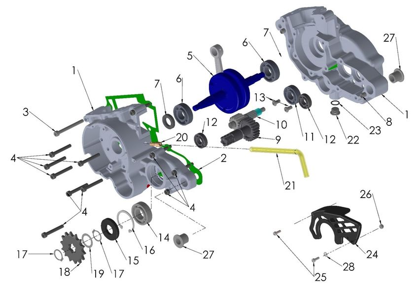
DISCLAIMER OF WARRANTY

This motorcycle is sold “as is” with all faults, obvious or not. There are no warranties expressed or
implied, including any warranty of merchantability and warranty of fitness for any particular purpose.

                                        “WARNING”
THE COBRA CX50FWE (KING) IS A COMPETITION MODEL ONLY AND IS NOT MANUFACTURED
FOR, NOR SHOULD IT BE USED ON PUBLIC STREETS, ROADS OR HIGHWAYS.

THE USE OF THIS BIKE SHOULD BE LIMITED TO PARTICIPATION IN SANCTIONED
COMPETITION EVENTS UPON A CLOSED COURSE BY A SUFFICIENTLY SKILLED RIDER AND
SHOULD NOT BE USED FOR GENERAL OFF-ROAD RECREATIONAL RIDING.

IMPROPER USE OF THIS MOTORCYCLE CAN CAUSE INJURY OR DEATH.

THIS BIKE IS INTENDED FOR EXPERIENCED RACERS ONLY AND NOT FOR BEGINNERS.

IT IS YOUR RESPONSIBILITY AS THE OWNER OF THIS COBRA MOTORCYCLE OR AS THE
PARENT, OR LEGAL GUARDIAN OF THE OPERATOR, TO KEEP THIS COBRA MOTORCYCLE IN
PROPER OPERATING CONDITION.

THIS BIKE WAS DESIGNED FOR RIDERS THAT WEIGH LESS THAN 80 LBS WITH FULL RIDING
GEAR AND SHOULD NOT BE OPERATED BY RIDERS THAT WEIGH MORE THAN THAT.

BE SURE THAT THE RIDER ALWAYS WEARS ADEQUATE SAFETY GEAR EVERYTIME HE OR
SHE RIDES THEIR COBRA MOTORCYCLE.

                               IMPORTANT SAFETY NOTICE

Failure to follow WARNING instructions could result in severe injury or death to the machine
operator, a bystander, or a person inspecting or repairing the machine.

CAUTION:
A CAUTION indicates special precautions that must be taken to avoid damage to the machine.

NOTE: A NOTE provides key information to make procedures easier or clearer.
                                                                                       MCCS2021SR.1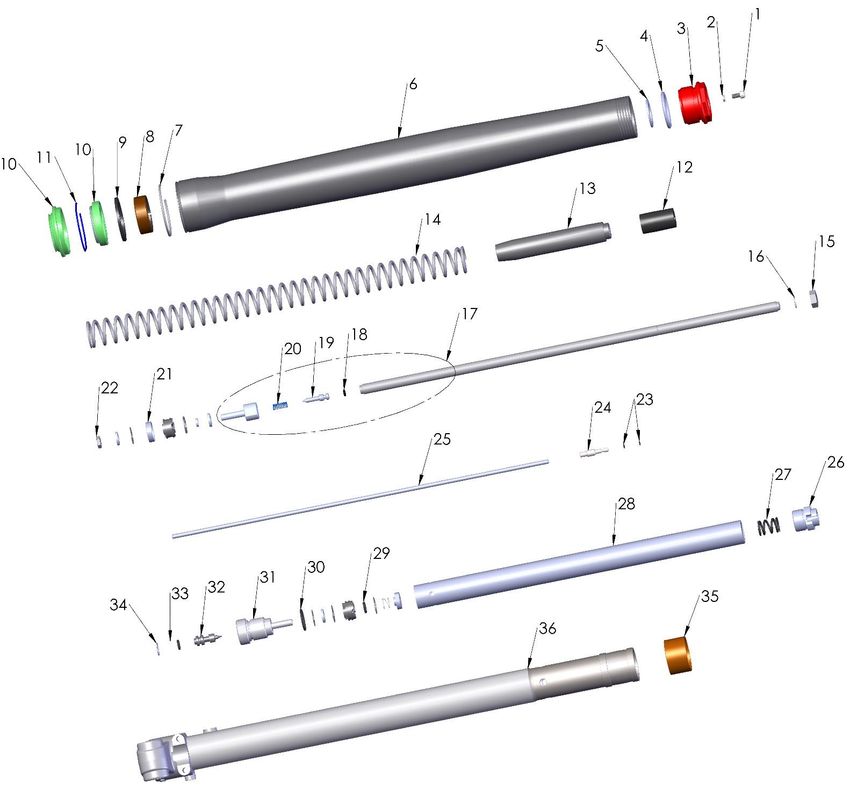
Table of Contents
GENERAL INFORMATION .................................................................................. 4

   SPECIFICATIONS - GENERAL........................................................................................................................ 4
   OPTIONAL SUSPENSION COMPONENTS ........................................................................................................ 5
   SPECIFICATIONS - TORQUE VALUES ............................................................................................................ 6
   BREAK-IN PROCEDURE ............................................................................................................................... 8
   STARTING PROCEDURE............................................................................................................................... 9

MAINTENANCE ................................................................................................. 10

   TIPS......................................................................................................................................................... 10
   SCHEDULE ............................................................................................................................................... 11
   REPLACING TRANSMISSION / CLUTCH LUBRICANT ...................................................................................... 12
   PROPER CHAIN ADJUSTMENT .................................................................................................................... 13
   REAR BRAKE MAINTENANCE ..................................................................................................................... 14
   AIR FILTER CLEANING ............................................................................................................................... 15
   FORK MAINTENANCE................................................................................................................................. 16
       Fork Air Bleeding................................................................................................................................ 16
       Fork Oil Replacement ........................................................................................................................ 17
   DISASSEMBLY PROCEDURE ....................................................................................................................... 17
   FRICTIONAL DRIVE (V3 CFD) .................................................................................................................... 18
   THROTTLE CABLE STRAIN RELIEF.............................................................................................................. 19
   PARTS – AIRBOX & INLET SYSTEM............................................................................................................. 20
   PARTS – BARS AND CONTROLS ................................................................................................................. 21
   PARTS – CARBURETOR ............................................................................................................................. 22
   PARTS – COOLANT SYSTEM ...................................................................................................................... 23
   PARTS – ELECTRICAL SYSTEM .................................................................................................................. 24
   PARTS – ENGINE – BOTTOM END AND TRANSMISSION ................................................................................ 25
   PARTS – ENGINE CLUTCH AND KICK LEVER ............................................................................................... 28
   PARTS – ENGINE – W ATER PUMP .............................................................................................................. 30
   PARTS – ENGINE – TOP END ..................................................................................................................... 31
   PARTS – FORKS & TRIPLE CLAMPS ........................................................................................................... 34
   PARTS – FORKS – LEG ASSEMBLY – BRAKE SIDE....................................................................................... 36
   PARTS - FORKS – LEG ASSEMBLY – NON-BRAKE SIDE ................................................................................ 38
   PARTS – FRAME I ..................................................................................................................................... 40
   PARTS – FRAME II .................................................................................................................................... 41
   PARTS – FRONT BRAKES .......................................................................................................................... 42
   PARTS – FRONT W HEEL............................................................................................................................ 43

                                                                                      2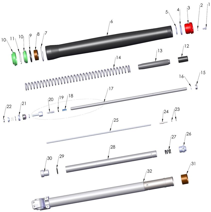
PARTS – PLASTIC BODYWORK & SEAT....................................................................................................... 44
    PARTS – REAR BRAKE .............................................................................................................................. 46
    PARTS – REAR W HEEL ............................................................................................................................. 48
    PARTS – SHOCK ....................................................................................................................................... 49
    PARTS – SHOCK - INSIDE .......................................................................................................................... 50
    PARTS – SWINGARM ASSEMBLY ................................................................................................................ 51

SERVICE ....................................................................................................................................... 52

    ENGINE SERVICE ...................................................................................................................................... 52
        Base Gasket Selection ....................................................................................................................... 53
        CFD Adjustment ................................................................................................................................. 55
        Engine Removal ................................................................................................................................. 55
        Complete Engine Disassembly Procedure ........................................................................................ 56
        Top End Disassembly Procedure ...................................................................................................... 56
        Splitting the Cases ............................................................................................................................. 57
        Engine Assembly ............................................................................................................................... 58
    CLUTCH ................................................................................................................................................... 59
        Clutch Assembly: ............................................................................................................................... 62
    IGNITION .................................................................................................................................................. 63
    COOLING SYSTEM .................................................................................................................................... 64
    FUEL & AIR SYSTEM ................................................................................................................................. 65
        Carburetor: ......................................................................................................................................... 65
        Reeds: ................................................................................................................................................ 67
    EXHAUST ................................................................................................................................................. 67
    REAR WHEEL PULLERS .............................................................................................................................. 68
    BRAKES ................................................................................................................................................... 68
    FRONT FORKS .......................................................................................................................................... 68
    REAR SHOCK ........................................................................................................................................... 69

TUNING ......................................................................................................................................... 69

    CLUTCH ................................................................................................................................................... 69
    GEARING.................................................................................................................................................. 71
        Front Fork Operation .......................................................................................................................... 73
        Fork Damping Adjustments ................................................................................................................ 73
        Rear Shock Adjustments ................................................................................................................... 74
    CARBURETION .......................................................................................................................................... 75

TROUBLESHOOTING................................................................................................................... 78

                                                                                      3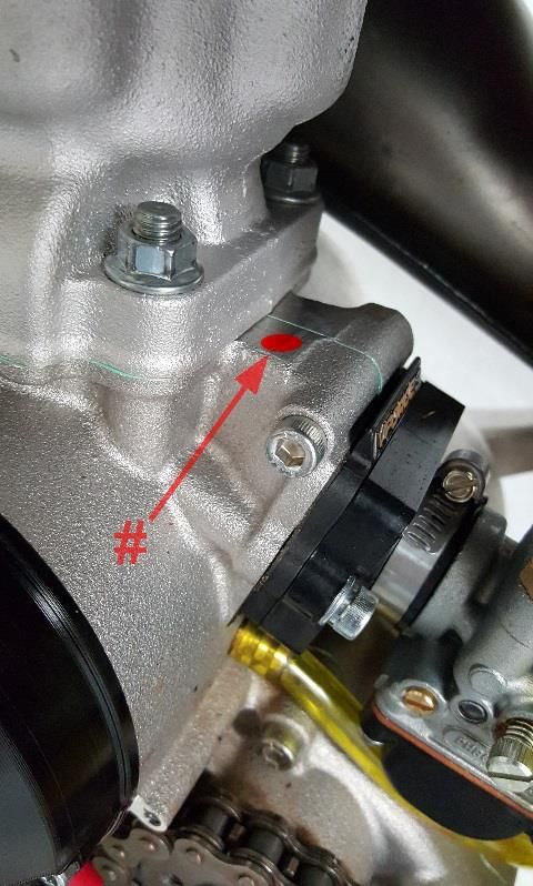
General Information
Specifications - General
             Items                                      CX50 FWE
Dimensions
 Wheelbase                         41” (1041mm)
 Wheel size                        10” (254mm) rear, 12” (305mm) front
 Seat height                       26” (660mm)
Engine
 Type                              2-stroke, single cylinder, reed valve
 Cooling system                    Liquid-cooled
 Coolant                           Spectro Year-Round Super Coolant
 Displacement                      49.8 cc
 Bore and stroke                   39 mm x 41.7 mm
 Ignition system                   PVL Analogic
 Spark plug                         – XS61 AUTOLITE, RN6YC & 8339 CHAMPION
    Gap                            0.023” – 0.025” (0.58 – 0.64 mm)
 Ignition timing                   0.035” (0.9 mm) Before Top Dead Center (BTDC)
 Fuel type                         High octane pump gasoline
 Premix Oil type                   Spectro Platinum SX2
 Premix oil ratio after break-in   32:1 – 60:1
 Carburetion                       19 mm Dell’Orto
    Slow (Pilot) Jet / Main Jet    55 / 93
    Needle                         W7-2
        Needle Clip Position       2nd slot from top of needle
    Float Height                   16mm + 0.5mm (0.63” + 0.020”)
Transmission
 Speed                             Single
 Final drive ratio                 15/38 T
 Chain                             102 links 420
 Transmission / clutch oil type    Cobra Venom 3 Shoe Clutch Milk
    Quantity                       300ml (10oz)
Chassis
 Front tire                        2.50 (60/100) - 12"
    Pressure                       16 psi minimum
 Rear tire                         2.75 (80/100) - 10"
    Pressure                       16 psi min. (20 psi for hard pack or rocky conditions)
 Front fork                        CARD 32mm USD Fully Adjustable w/ Smart Leg
    Fork oil type                  5wt Spectro Fork Oil
    Fork oil amount                150 ml
    Std settings                   Smart leg: 1.5 out, Compression and rebound 2 out
 Rear shock (std. settings)        Compression: Low 12 out, High 15 out
                                    Rebound 16 out, Race sag 75mm, Free sag 25mm
                                              4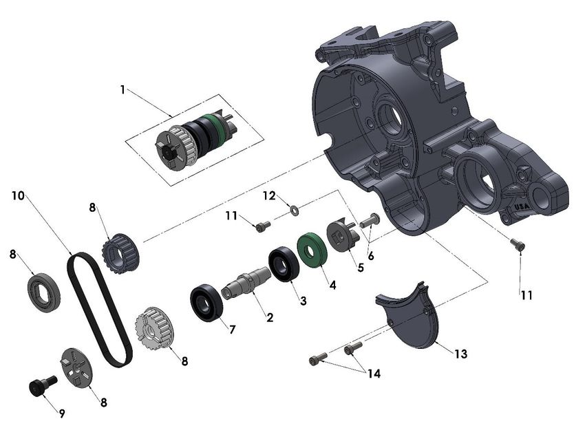
Optional Suspension Components
   Weight of Rider (lb)   Fork Spring         Shock Spring
    Less than 50 lb       0.23 kg/mm        green, 2.9 kg/mm
                          KCCS3223              SCKGFX29
         50 – 60          0.23 kg/mm        black, 3.1 kg/mm
                          KCCS3223              SCKGFX31
          60-75           0.25 kg/mm         red, 3.3 kg/mm
                          KCCS3225              SCKGFX33
    Greater than 80       0.27 kg/mm        yellow, 3.5 kg/mm
                          KCCS3227              SCKGFX35

                                        5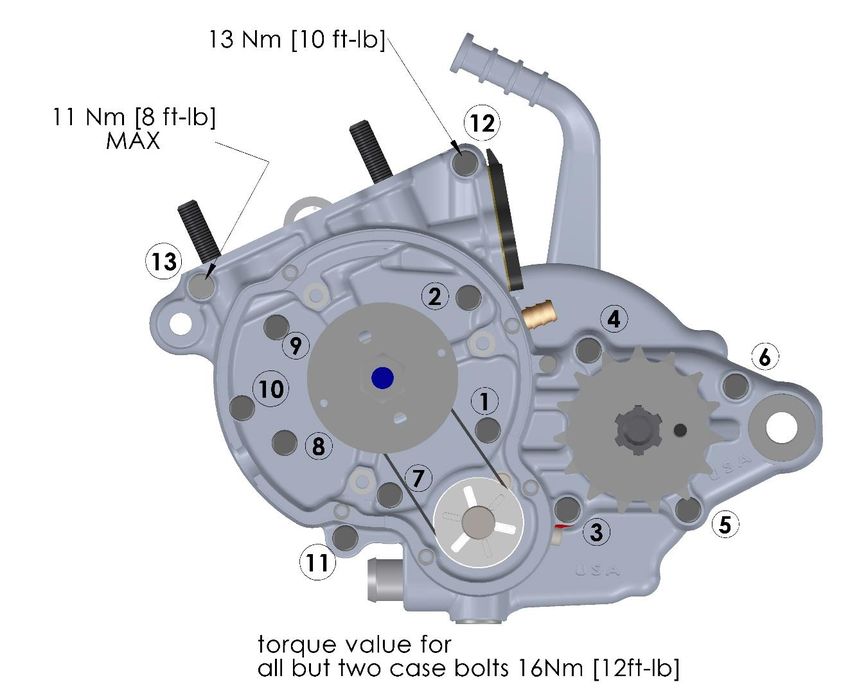
Specifications - Torque Values
                                       Torque Value                         Size &
Fastener                                                       Loctite TM
                                 ft-lb     in-lb     Nm                     Remarks
Cylinder head nuts                 9        110      12                     M6 x 1.0
Cylinder nuts                     22        265      30                     M8 x 1.25**
Crankcase bolts                      See the next page                      M6 x 1.0
Spark plug                      (SP)      (SP)      (SP)                    M14 x 1.25
Stator bolts                     2.1         25      2.8                    M5 X 0.8
Ignition rotor nut                30        400      45          243        M10 x 1.25
Stator cover bolts               1.7         20      2.3         243        M4 X 0.75
Clutch cover bolts               5.8         70      7.9                    M6 X 1.0
Clutch nut                        40        480      54          263        M10 x 1.25
Clutch bolts                      12        144      16          263        M6 x 1.0
Engine mount bolts                22        265      30                     M8 X 1.25
Swingarm pivot                    21        250      28                     M14 X 2.0
Shock bolt                        35        420      47          243        M10 x 1.5
Water pump impeller                3         36       4          263        M5 x 0.8
Water pump pulley                 10        124      14          243        M6 x 1.0
Intake manifold bolts            4.6         55      6.2                    M6 X 1.0
Rear axle nuts                    21        250      28                     M12 X 1.25
Rear sprocket bolts               21        250      28                     M7 X 1.0
Front axle aluminum bolt          18        221      25       Moly lube     M10 X 1.25
Fork guard alum bolts              6         88       8         243         M6X1, ALUM
Front axle pinch bolts           7.5         88      10                     M6 x 1.0
Brake caliper bolts                9        106      12          243        M6 x 1.0
Brake caliper to carrier           7         84      9.5         243        M6 x 1.0
Brake pad secure                   3         36       4                     M5 x 0.8
Banjo bolts – brakes              15        177      20                     M8 x 1.25
Brake rotor bolts                  9        108      12          243        M5 x 0.8
Triple clamp bolt (top)            8         90      10                     M8 x 1.25
Steering stem pinch bolt         9.5        115      13                     M8 x 1.25
Triple clamp bolts (bottom)        6         72       8                     M6 x 1.0

** Use a ‘crows foot’ attachment oriented 90° to the torque wrench

(SP) To apply the proper torque to the spark plug when inserting, one must first screw the
spark plug in until the metal gasket ring causes resistance and then turn another 1/8 to ¼ turn.

                                               6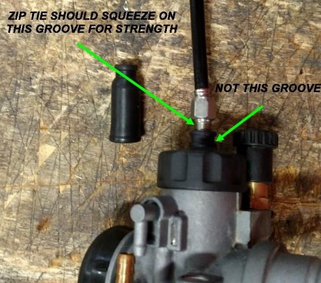
Proper case bolt torque values

Torque the engine case bolts in the pattern shown above. The upper two bolts have a different
toque value compared to the others.

Proper torquing procedure would have you lubricating the threads with 30W oil, torquing the
bolts all first to an intermediate torque value of 10-12 Nm and then once they are all at that
value, proceed back at bolt #1 and toque each bolt further up to the final value.

                                                7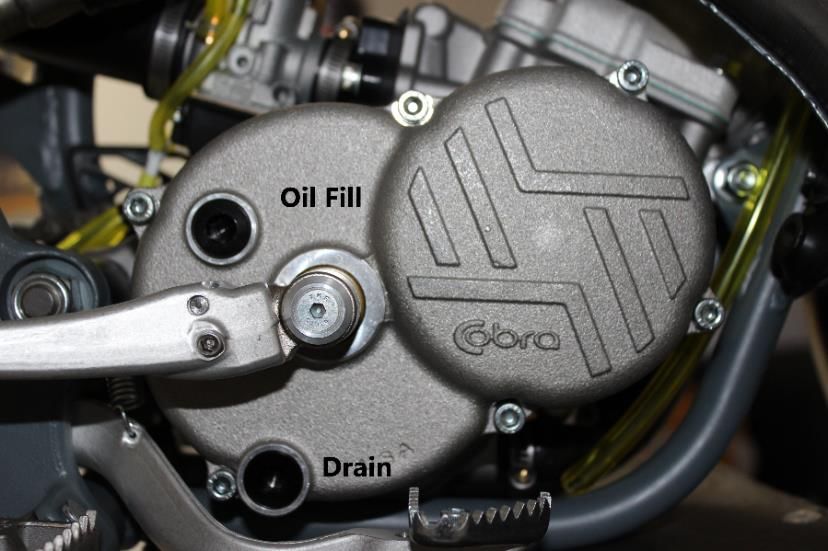
Break-In Procedure
Your Cobra CX50 FWE King is a close-tolerance high performance machine and break-in time
is very important for maximum life and performance. The CX50 can be ridden hard after the first
½ hour break-in time.
Cobra recommends Spectro Platinum SX2 premix oil with high octane
pump gas mixed at 32:1 (4 oz oil to a gallon of gas).
CAUTION: Failure to use proper fuel, oil, or fuel/oil mixture may result in premature engine
wear or damage to the machine.
Adhering to the following break-in schedule will result in long lasting high performance machine.
Start bike on stand
First 5 minute period, operate the bike on the stand with a combination of idle and high
RPM operation. (avoid prolonged high RPM but spin the rear wheel good at least once or
twice per minute)
Allow bike to cool
Ride for 15 minutes maximum (avoid prolonged high RPM operation and avoid abusing the
clutch with throttle blipping.
Cool and inspect bike for loose fasteners.
Next ½ hour of operation, avoid prolonged operation at Wide Open Throttle.
After 1 hour of operation
o Check for loose bolts and nuts on the bike and retighten as necessary (proper toque
values are listed under Specifications).
o Clean the carburetor bowl.
o Change the transmission / clutch lubricant.
Check CFD torque and adjust as necessary
After 8 hours of operation
o Change the fork oil.
o Have a Certified Cobra Mechanic change the shock oil.
Your bike is now ready for the highest level of competition!
NOTE: During break-in the bike will likely lose some engine coolant through the radiator
overflow hose. Losing up to 4 oz (120 ml, ½ cup) is normal. Proper coolant level is to the
bottom of the filler neck. Removing the radiator cap and looking inside is the only way to check
the coolant level.
Never open the radiator cap of a machine that has a hot or warm engine or one that has recently
been ridden. Burning and scalding could occur.
8Starting Procedure
Before starting the machine inspect the following:
Tire pressure
Chain tension
Coolant level
Proper wear on chain rollers and sliders
Handlebar tightness
Throttle assembly movement/cable adjustment
Air Filter
Check for loose nuts and bolts
Turn the fuel on by rotating the fuel petcock knob to the vertically downward position
(reserve position is horizontally forward)
NOTE: For best results from your Cobra Motorcycle use only the recommended fuels. Testing
has shown that most ‘race’ fuels actually degrade performance.
Always wear a helmet and other protective riding gear.
When your pre-ride inspection is complete the bike may be started. For a cold engine follow
this procedure.
1. Place the motorcycle on a stand of sufficient strength that positions the motorcycle in a
level upright position with the rear wheel off the ground.
2. Pull up the choke knob and turn it to lock it.
3. Kick start the engine.
4. Rev the engine in short spurts, turning the throttle no more than 1/4 open until the engine
will run without the choke.
5. Verify a functional engine shut-off switch by shutting off the engine.
6. Restart the engine and proceed with riding when the engine is sufficiently warm (i.e. the
side of the cylinder is warm to touch).
CAUTION: Never rev an engine full throttle when it's cold or slightly warmed up and, for best
clutch performance, warm up the bike before taking off.
This is a high performance race motorcycle. Too much application of throttle will likely land
your little racer on his or her arse. Fenders can be replaced but bruised egos and other body
parts take longer.
CAUTION: Cobra recommends that you tell your child to take it easy the first couple of
minutes in practice until the engine comes up to full operating temperature.
CAUTION: Make sure your riders foot is not resting on the foot brake while they are riding.
9Maintenance
A properly maintained machine is safer, faster, and more fun to ride. It is important that you
adhere to this maintenance schedule so as to promote the longevity of your Cobra Motorcycle.
Tips
1. Recommended lubricants:
a. Cobra Clutch Milk is by far the best auto clutch lubricant. It is a full synthetic
lubricant that has been specifically formulated for Cobra’s auto clutch and has;
Exceptional film strength over petroleum based oils or synthetic blends.
Extreme temperature tolerance.
NO frictional modifiers.
Dispersant package to keep clutch fibers in suspension so they can be
flushed out when the oil is changed.
Extremely low viscosity for minimal drag and ‘windage’.
b. Spectro Platinum SX2 oil is the recommended premix oil because:
Its Ester base leaves a film on all parts at all times. No metal to metal
startups or corrosion potential.
Exception film strength over petroleum based oils or synthetic blends.
Easily atomizes and burns completely.
Does not fall out of suspension from premix in cold weather.
Produces virtually no coking deposits, leaving pistons, rings and heads
extremely clean with minimal pipe ‘spooge’.
2. Filling your transmission with more than 8.0 oz (235 cc) of lubricant may help to transfer
heat from the clutch. Filling with more than 12 oz (350 cc) will degrade performance.
3. The cylinder base gasket has been ‘fitted’ for your engine. The code number stamped
into the engine cases will guide you to what thickness base gasket is required during a
common top end service. See the service section of this manual to correspond a code
number with a base gasket part number.
4. Evaluate the bikes jetting only after it has been warmed up to race temperatures.
5. New chains will stretch on first use. Never install a new chain prior to a race. Always
‘break’ them in during practice.
6. Your Cobra Motorcycle has a 10 digit VIN (Vehicle Identification Number). The first three
digits indicate the model while the sixth and seventh indicates the model year.
a. Example, FWExx17xxx is a 2017 CX50 SR.
7. Because of the amount of heat generated by the clutch and engine during extended
periods of riding, it is advisable to remove the ignition cover afterward to allow the ignition
to cool off. The heat transfers through the cases and can damage the stator as it cools off
because of lack of airflow around the stator.
8. If you ever need to weld anything on the bike, disconnect the spark plug cap, unplug the
ignition, disconnect the kill switch, scrape the paint bare near the area to be welded and
put the ground clamp as close to the area to be welded as possible.
Be sure the fuel tank and carburetor have been removed and safely located away from the
welding process.
109. The frame is 4130 Chrome Moly and it is important to weld it with the proper rod and heat
settings set as light as possible. Cobra recommends replacing the frame with a new one
if the old one becomes damaged. Use ER70S6 filler if welding on the frame.
10. If your kick-starter lever does not return properly, first try loosening the six kick/clutch
cover screws ½ turn. Hold the kick lever ½ way down while retightening the six screws
starting for the center and working out
11. Inspect CFD slip torque after the 2nd ride and then again after the 6th ride. After this follow
the recommended schedule below.
12. Check proper clutch engagement before and after each ride. If the clutch is engaging
properly DO NOT feel the need to take the clutch apart to; measure the spring stack,
clean the stack, replace the springs, etc... Cobra has worked very hard to make a clutch
that is low maintenance and so only take it apart if it NEEDS to be maintained.
Schedule
Prior to each ride
o Check the air filter (clean and re-oil as necessary).
o Insure the smooth operation of the throttle cable (throttle soundly ‘clacks’ shut).
o Check for frayed strands of the throttle cable inside the throttle housing and replace
if necessary.
o Check for adequate tire pressures and adjust if necessary.
o Check all nuts and bolts for proper torque and re-torque if necessary.
o Spray all moving parts with WD40 or other light oil.
o Check drive chain for
Proper tension and adjust if necessary.
Adequate lubrication and lubricate if necessary.
o Insure that the ignition stator and rotor are clean and dry.
o Check the frame for cracks in the metal or cracks in the paint that might indicate that
the metal has been stressed beyond it’s safe limits. Replace or get properly re-
welded as necessary.
o Check the rims for signs of stress; like cracks around the rim, spokes, and hub.
o Equalize the pressure in the forks with atmosphere. Release any pressure built up
inside the fork by loosening the bleed screw on the fork cap. Retightening after
pressure is released.
Every 2 hours of operation
o Replace the transmission oil.
o Check the CFD torque.
Every 10 hours of operation
o Replace the fork oil.
o Have the shock oil replaced by a Certified Cobra Mechanic.
11Replacing Transmission / Clutch Lubricant
Tools needed:
5mm allen wrench
Minimum of 300 cc (10 oz) Cobra Venom 3 Shoe Clutch Milk (Part #MCMUGF32).
Procedure:
1. Begin this procedure with a bike that has been ridden more than 5 minutes but less than 10
minutes. It is desired to have the engine warm enough so that the oil is ‘runny’ but not so
hot that there is risk of being burned by the engine or the oil.
Hot oil and hot components on the motorcycle may cause burns.
2. Remove the oil drain plug located on the right side of the engine, on the clutch cover, near
the brake lever (figure 1).
Figure 1
3. After it has drained, reinstall the plug, being sure that the gasket is in place.
4. Reapply oil from oil fill plug 300 cc (10 oz) Cobra Venom 3 Shoe Clutch Milk thru the oil fill
plug.
NOTE: Putting additional oil, up to 350 cc (12 oz), can help clutch life. More than 350 cc (12
oz) will degrade engine performance.
5. Reapply the oil fill plug, hand tight, being sure the gasket is in place.
CAUTION: Cobra has spent considerable time and money developing the proper lubrication to
handle the harsh environment of the automatic clutch and transmission of this motorcycle.
Cobra’s specially developed Cobra Venom 3 Shoe Clutch Milk (Part #MCMUGF32) was
formulated to provide superior lubrication and cooling capability over extended periods of time
and is the recommended lubricant for your Cobra motorcycle.
12Proper Chain adjustment Figure 2
Tools required for chain adjustment
19 mm wrench or socket
13 mm wrench or socket
1. Make sure that the rear wheel is aligned properly.
2. For proper adjustment, the chain should have
35mm (1.378”) free movement just behind the
chain guard with no load on the bike (figure 2)
CAUTION:
Sit on the bike and verify that the chain has a minimum of 12mm (1/2”) free movement when the
chain is at its tightest point.
3. If the chain requires adjusting, loosen the axle
with a 19 mm wrench and tighten the chain by
rotating the adjustor bolts clockwise (CW) or
loosen the chain by rotating the adjustor bolts
(CCW).
4. Ensure proper alignment of the rear wheel by
making sure there are equal amounts of the
alignment holes (figure 4) showing on each
side of the wheel.
5. Retighten the axel bolt to 25 ft-lb (34 Nm).
6. Retighten the adjustor bolt (figure 3)
Figure 3 (top), Figure 4 (bottom)
13Rear Brake Maintenance
CAUTION: Too little brake pedal free-play will allow the brake pads to drag causing the pads
to wear prematurely and possible engine component failures. Too much free-play will not allow
the rider to apply the brakes quickly.
1. Set pedal height/position first, then
2. Set pedal free play.
Brake pedal height can be adjusted with the bolt located above the rear of the brake pedal.
The free-play is adjusted with the adjustable plunger on the end of the brake pedal.
CAUTION: Use New container of Spectro DOT4 Racing
Brake Fluid
Setting rear brake pedal position (see figure 2b):
1. Loosen the height adjust lock nut (10mm wrench)
2. Adjust the height adjust screw (5mm Allen
wrench) so that the lever is comfortably reachable
in both:
a. Standing riding position, and
b. Sitting riding position.
3. Tighten the height adjust lock nut.
CAUTION: Adequate pedal free play is required so that
the brake pads do not drag on the rotor.
Make sure that the free play locking clip is installed such
that one must push forward, toward the front of the bike, Figure 2b
to remove. Otherwise the clip is apt to come undone while riding.
To adjust freeplay (see figure 2b):
1. Loosen the lock nut (10mm).
2. Undo the free play locking clip from around the brake adjustor (plunger), with your hand
by pushing it forward.
3. Slide the pin of the locking free play locking clip from the brake lever
4. Adjust as needed by rotating the clevis on the end of the adjustor (plunger).
NOTE: Turning the clevis Clockwise will lengthen the adjustor (plunger), removing free play
from the system, and turning the clevis Counter-Clockwise will shorten the adjustor (plunger)
adding free play to the system.
14Air Filter Cleaning
Removal:
Remove the seat
Loosen the clamp connecting the rubber boot of the
filter to the carborator
Push the rubber boot from the bottom up and out of the
airbox
CAUTION: Pulling on the filter instead of pushing up on the
boot may cause tearing of the filter.
NOTE: Using one hand to control the filter end while removing will help reduce the risk of
damage to the filter
Pull the tab on the filter to remove it from the
rubber boot
Clean the airbox of dirt.
Cleaning
CAUTION: Pay particular attention to clean any particles from the airbox between the filter
location and the carburetor.
NOTE: Cobra has available a carburetor cover that allows easy Carburetor Cap
cleaning of the airbox.
CAUTION: Cleaning the air filter with alcohol or using filter oil that
contains alcohol may cause filter glue separation.
1. Install the cover (RCMU0109) over the carburetor inlet
2. Spray out the airbox.
Do not clean the air filter with gasoline or other highly volatile petroleum product. Diesel fuel or
kerosene would be preferred but caution should still be taken. Hot soapy water works well.
1. Clean the filter in hot soapy water to remove all dirt particles.
2. Allow it to dry thoroughly.
3. Saturate with filter oil and remove excess.
NOTE: It’s very important to oil your filter consistently each time because varied amounts of oil
will change your carburetor jetting.
15Assembly:
1. Place the filter back onto the rubber boot.
2. With one hand on the filter, feed the rubber boot into the airbox
CAUTION: In order to avoid air filter tearing, make sure to place a hand on the filter while
feeding the boot through the airbox.
NOTE: Make sure you change or clean your filter after each moto. We recommend carrying
multiple filters in your toolbox, one for each practice session and moto.
NOTE: Make sure you change or clean your filter after each moto. We recommend carrying
multiple filters in your toolbox, one for each practice session and moto.
Fork Maintenance
Cobra strongly recommends that a professional service technician conduct all internal
maintenance other than changing springs and oil. This will help to ensure safe and consistent
operation.
For routine maintenance, the chart below provides suggested service intervals for common
procedures:
Each Ride 10 hours 20 hours As Needed
Bleed excess air X
Change Oil X
Change X
Seal/Swiper
Change Bushings X
Fork Air Bleeding
Tools required
3mm hex key (Allen wrench)
During normal operation, both fork legs will build up air pressure. This pressure acts as an
additional spring so it must be bled on a regular basis to maintain consistent suspension
operation. Before each ride, loosen the socket head cap screw located at the front of each fork
cap far enough so that any excess pressure in the leg is relieved. After excess air is bled off,
retighten the screw to 5 in-lb. Be careful not to lose or damage the sealing ring that is located
under the head of each bleed screw.
16Fork Oil Replacement
Tools required
32mm Fork Cap Tool (MCMUTL32)
8mm Allen wrench
4 & 5 mm hex key (Allen wrench)
9/16 wrench
Mallet
5 wt. Spectro fork oil
Disassembly procedure
1. Remove the front wheel and axle (8mm Allen wrench).
2. Remove brake line clamp.
3. Remove the brake caliper from the fork leg (4mm hex key).
4. Loosen the top pinch bolts (6mm hex key).
5. Loosen the fork caps (32mm fork cap tool).
6. Loosen the bottom pinch bolts (5mm hex key).
7. Remove the fork legs from the triple clamps (5 and 8mm hex key).
8. One leg at a time
a. Remove the fork cap from the fork tube.
b. Pull the fork spring down to gain access to the fork cap jam nut and secure it with a
9/16 wrench.
c. Holding in one hand the 9/16 wrench use the fork cap wrench to unscrew the fork
cap from the damper rod.
d. Remove the fork spring pad, and fork spring.
e. Inside the damper rod, the rebound adjustment screw pin is resting and will fall out
of the damper rod when the fork is inverted. Try to catch it before it falls into your oil
bucket.
f. Invert the fork and allow the oil to drain completely. Working the damper rod up and
down will speed up the draining process.
Assembly procedure
1. Fill the fork with 150ml of fork oil.
2. Work the damper rod up and down to allow the fork cartridge to fill with oil.
3. Install the rebound adjustment screw pin into the damper rod.
4. Install the fork spring and spring pad.
5. Extend the damper rod completely and Compress the fork spring enough to begin
threading the fork cap back onto the damper rod.
6. Make sure that the fork cap threads onto the damper rod completely before it makes
contact with the jamnut.
7. Tighten the jamnut.
8. Tighten the fork cap to the fork leg outer
9. Install each leg back into the triple clamp. Torque each pinch bolt to 8N-m (6 ft-lb) making
sure both legs are set to the same height in the clamps.
1710. Pump the fork leg several times to verify that it operates smoothly.
11. Reinstall the brake caliper.
12. Reinstall the front wheel (25 ft-lb, 34 Nm).
Frictional Drive (V3 CFD)
The Cobra Frictional Drive (CFD) is essentially an adjustable slip clutch that dissipates torque
spikes transmitted from the rear wheel to the rest of the drive line and engine. Instead of these
torque spikes potentially damaging internal components, the CFD allows the transmission to
slip with respect to the engine. For this to
occur, the CFD must function properly by
‘slipping’ above a minimum torque value.
The safe minimum slip torque of the CFD
should be checked every 2 hours of
operation, after break-in.
The slip torque value should be above 80 ft-
lb (108 Nm) measured at the sprocket with
the following process.
To properly measure the minimum
torque at which the CFD (Cobra
Frictional Drive) slips
1. Remove the oil fill plug and install the check tool/pin MCMUTL40.
2. Make sure that it is threaded in completely until it bottoms out.
3. Install the Sprocket Socket CFD torque checking tool (MCMUTL15) on the output shaft
protruding through the sprocket.
CAUTION: It may be necessary to remove the
ECKGSR03 sprocket clip, or the sprocket entirely, to
ensure good engagement between the tool and the shaft
4. Verify with a torque wrench applied to the
Sprocket Socket that the V3 CFD does not slip
below 108 Nm (80 ft-lb) in either direction.
5. If there is slippage below 108 Nm (80 ft-lb)
remove the cotter pin and tighten the castle nut
on the CFD one more position (it is a left hand
thread nut so you must turn it counter clockwise)
NOTE: This V3 CFD torque checking method is
possible do to with the chain on. Just put the bike on a
stand so that the rear wheel can turn freely.
18NOTE: The CFD hubs can be removed with the universal puller (MCMUTL70).
If it slips below the value, the CFD must be readjusted as per described in the service section
of this manual.
NOTE: If the bike makes a whir, whir, whir, sound coming from the clutch side engine cover it
is very probable that the CFD has slipped enough that the brass bushing has worn sufficiently
to let the gear operate off center. Time to install a CFD refresh kit (EKMU0033).
Throttle Cable Strain Relief
To reduce the likelihood of the throttle cable being pulled from top of the carburetor it is
recommended to install two 8” zip ties as shown in the pictures below to strain relief the throttle
cable to the carburetor top. One zip tie securing the boot to the cable the other securing it to
the threaded cable adjuster.
We will be doing this in production going forward.
This applies to all Cobra CX50’s
NOTE: For the strongest grip, the bottom (left in the
pictures) zip tie should be squeezing on the groove
between the hex adjuster and the top, NOT the
groove in the carb top.
19Parts – Airbox & Inlet System
Air Box
REF
PART # DESCRIPTION
#
RACS0019 CARBURETOR – 19MM W/ DEEP WELL
1 RCCS0008 AIRBOX
2 HCSP0004 SCREW – PLASCREW - ALUMINUM
3 RCCS0009 AIR FILTER ASSY
4 TCC60008 MUDFLAP
5 MCKGHO01 HOSE CLAMP – BOOT TO CARB
6 MCKGHO04 HOSE CLAMP – CARB TO MANIFOLD
7 RCMU0036 INLET MANIFOLD
8 ECMU0246 REED CAGE ASSEMBLY WITH REEDS VFORCE
9 ZCCS0001 GASKET – REEDS TO ENGINE
10 HCBC0603 M6X30mm SOCKET HEAD CAP SCREW
11 HCWF0601 6mm FLAT WASHER
12 RCCM1301 VELOCITY STACK (SCREWS ONTO CARB)
13 ECCS0030 REED REPLACEMENT KIT
14 RCCS0001 BOOT – AIR FILTER
15 HCHA0003 6mm CLIP NUT
16 RCMU0109 CARBURETOR INLET CAP
20Parts – Bars and Controls
Bars and Controls
REF # PART # DESCRIPTION
1 FAMU0014 HANDLEBAS – PRO TAPER MICROBARS – COBRA BEND
2 TCMU0021 GRIPS (SET OF TWO) – MICROGRIPS – RED / GRAY
3 FAMU0016 THROTTLE ASSEMBLY – PRO TAPER COBRA
3A FAMU0015 TUBE ASSEMBLY – THROTTLE – 2 PIECE PRO TAPER MICRO
3B HCBC0525 M5 X 25 SHCS – THROTTLE ASSEMBLY
3C FCMU0041 STOP RING – MICRO BAR THROTTLE
4 FCPW0004 CABLE COVER
5 FCMU0021 THROTTLE COVER
6 FCMU0019 THROTTLE CABLE
6A HCNJ0801 NUT – 8MM JAM
7 SEE FRONT BRAKE
8 FCMU0171 KILL SWITCH ASSEMBLY
9 HCBC0806 M8X30mm SOCKET HEAD CAP SCREW (4 REQ’D)
10 TCMU0060BLK BAR CLAMP - BLACK
ACCESSORY MCMUAM11 GRIP DONUT – PAIR – PRO TAPER MICRO BAR
HANDLEBAR KIT- PRO TAPER MICRO- WITH COBRA
ACCESSORY FKMU0004
THROTTLE AND GRIPS
ACCESSORY TCMU0061 BAR RISER KIT
21Parts – Carburetor
Carburetor
REF. # PART # DESCRIPTION
1 RACS0019 CARBURETOR
2 RCMU0307 GASKET – CARB TOP
3 RCMU0003 CABLE ADJUSTOR
5 RCMU0046 TOP CARB THREAD ON
6 RCMU0102 RUBBER CABLE CAP SEAL
7 RCMU0004L SLIDE SPRING - LIGHT
8 RCMU0028 NEEDLE RETAINER PLATE
9 RCMU0007 NEEDLE CLIP
10 RCMU0340 SLIDE - #40 BIG AIR
11 RCMU0601 NEEDLE – W7
12 RCMU0204 CHOKE ASSEMBLY
12A RCMU0209 O-RING CHOKE ASSEMBLY
13 RCMU0009 FUEL MIXTURE SCREW #16
14 RCMU0011 IDLE ADJUSTMENT SCREW #18
15 RCMU0201 SCREW – FLOAT BOWL
20 RCMU00xx PILOT JET, xx denotes size
22 RCMU0262 ATOMIZER 2.62 AU STANDARD*
23 RCMU0107 FLOAT NEEDLE
24 RCMU0012 DIFFUSER #20
25 RCMU0016 FLOAT RETAINER PIN
26 RCMU0301 FLOAT #7
27 RCMU0103 FLOAT BOWL GASKET
28 RCMU0306 FLOAT BOWL W/ DEEP WELL
29 RCMU00xx MAIN JET, xx denotes size
30 RCMU0044 MAIN JET EXTENSION
NOT SHOWN RCCM1301 VELOCITY STACK
NOT SHOWN RCCS0006 FUEL LINE, 5”
NOT SHOWN MCMUCL04 HOSE CLAMPS – FUEL LINE
NOT SHOWN RCMU0020 ELBOW - CARB VENT
NOT SHOWN RAMU0001 CANNULUS - Y STYLE CARB VENTS
ACCESSORY RCMU0330 SLIDE - #30 BIG AIR
ACCESSORY RCMU0350 SLIDE - #50 BIG AIR
ACCESSORY RCMU0360 SLIDE - #60 BIG AIR
ACCESSORY RCMU0026 NEEDLE - W4
ACCESSORY RCMU0602 NEEDLE - W16
*Different sizes are available upon request
PILOT JET MAIN JET*
48 RCMU0048 88 RCMU0088 94 RCMU0094
50 RCMU0050 89 RCMU0089 95 RCMU0095
52 RCMU0052 90 RCMU0090 96 RCMU0096
55 RCMU0055 91 RCMU0091 97 RCMU0097
60 RCMU0060 92 RCMU0092 98 RCMU0098
65 RCMU0065 93 RCMU0093
*Larger and Smaller sizes are available upon request
22Parts – Coolant System
Coolant System
REF # PART # DESCRIPTION
1 FCMU0081 RADIATOR – (2 REQ’D)
2 FCMU0069 LOUVER (2 REQ’D)
3 MCMUGR12 GROMMET – RADIATOR MOUNTING (4 REQ’D)
4 HCSP0610 FASTENER – RADIATOR MOUNTING (4 REQ’D)
5 FCMU0020 CAP, 1.3 BAR
6 FCKG0214 RADIATOR OVERFLOW HOSE, 22”
7 FCMU0322 HOSE – USED AT CLAMP
8 FCMU0036M “T” FITTING – COOLANT – WITH CLAMP
9 MCMUCL09 HOSE CLAMP – 11 TO 20MM (2 REQ’D AT RADIATOR)
10 MCMUCL11 HOSE CLAMP – SOLID CRIMP (4 REQ’D)
11 FKAM0053 KIT – HOSE – VENOM ENGINE BLK 2021 & NEWER
11 FKAM0053RED KIT – HOSE – VENOM ENGINE RED 2021 & NEWER
11 FKAM0053BLU KIT – HOSE – VENOM ENGINE BLUE 2021 & NEWER
14 MCMUCL07 CLAMP – HOSE – 14 TO 27mm (2 REQ’D AT ENGINE)
23Parts – Electrical System
Electrical System
REF # PART # DESCRIPTION
1 ICMU0044 COIL/CDI W/SPARK PLUG CAP
2 ECMU0010I SPARK PLUG, AUTOLITE IRIDIUM
3 FCMU0171 KILL SWITCH ASSEMBLY
4 HCBC0514 M5X14mm SOCKET HEAD CAP SCREW (2 REQ’D)
5 HCWF0501 5mm FLAT WASHER (2 REQ’D)
6 ICMU0023 STATOR WITH GROMMET
7 HCBC0535 M5X35mm SOCKET HEAD CAP SCREW (2 REQ’D)
8 HCBC0525 M5X25mm SOCKET HEAD CAP SCREW
9 HCWF0601 6MM FLAT WASHER FOR STATOR (3 REQ’D)
10 ICMU0042 ROTOR
11 EKMU0035 KIT – PULLEYS, SPACER & BELT RETAINER
12 HCNS1001 NUT M10
13 ECC60166 IGNITION COVER
14 HCBC0401 M4X25mm SOCKET HEAD CAP SCREW (3 REQ’D)
NOT SHOWN ICMU0012 WOODRUFF KEY
NOT SHOWN FCMU0030 COVER – KILL SWITCH SCREW
ACCESSORY ICMU0017 SPARK PLUG CAP – 0
TOOL MCMUTL70 TOOL – CLUTCH & 50CC FLYWHEEL PULLER
TOOL ECMU0079 TOOL – DIAL INDICATOR – SPARK TIMING
24This Page Left Blank Intentionally
25Parts – Engine – Bottom End and Transmission
26Engine Bottom End and Transmission
REF
PART # DESCRIPTION
#
1 EKMU0016 CRANKCASE SET WITH BEARINGS, SEALS & GASKET
2 ZCMU0015 GASKET, CRANKCASE CENTER
3 HCBC0665 M6X65mm SOCKET HEAD CAP SCREW (1 REQ’D)
4 HCBC0604 M6X35mm SOCKET HEAD CAP SCREW (12 REQ’D)
5 ECMU0258 CRANKSHAFT - 3 SIDE SPLINE & INTERNAL W/P
6 ECMU0016 BEARING, CRANKSHAFT (2 REQ’D)
7 ECMU0118 SEAL, CRANKSHAFT (2 REQ’D)
8 ECMU0122 DOWEL (HOLLOW), ENGINE CASE ALIGNEMENT (2 REQ’D)
9 ECMU0999 OUTPUT SHAFT, TRANSMISSION WITH GEAR SUPR WIDE
10 ECMU0268 SECONDARY SHAFT, TRANSMISSION WITH GEAR
11 ECMU0001 BEARING, TRANSMISSION SECONDARY SHAFT
12 ECKG0031 BEARING TRANSMISSION SHAFT, (1 EACH CASE HALF)
14 ECKGBR01 BEARING, TRANSMISSION OUTPUT SHAFT
15 ECMU0236 SEAL, OUTPUT SHAFT
16 ECMU0237 SNAP RING – OUTPUT BEARING
17 ECKGSR03 SNAP RING, SPROCKET (2 REQ’D)
18 PCKG0015 SPROCKET, 15 T (STANDARD, 13, 14 & 16 available)
19A ECMU0176 SHIM – SPROCKET .2MM THICK
19B ECMU0177 SHIM – SPROCKET .3MM THICK
19C ECMU0178 SHIM – SPROCKET .5MM THICK
20 ECMU0233 FITTING, CRANKCASE VENT – LARGE
21 ECMU0557 VENT HOSE, CRANKCASE
22 ECMU0272BLK OIL FILL PLUG, BLK
23 ZCMUB014 O’RING – OIL FILL PLUG
24 ECMU0289 COVER – CHAIN AND SPROCKET
25 HCBC0412 M4 X 12MM SOCKET HEAD CAP SCREW (2 REQ’D)
26 HCNL0401 M4 LOCKNUT
27 ECC60028 BUSHING – ENGINE PIVOT – (1 IN EACH SIDE CASE)
28 HCWF0401 4MM FLAT WASHER
ZKMU2016 COMPLETE GASKET KIT
EACS2021 COMPLETE VENOM ENGINE
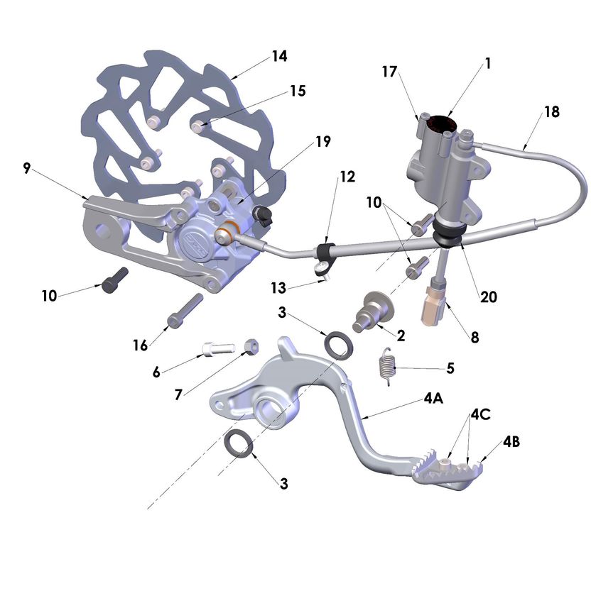
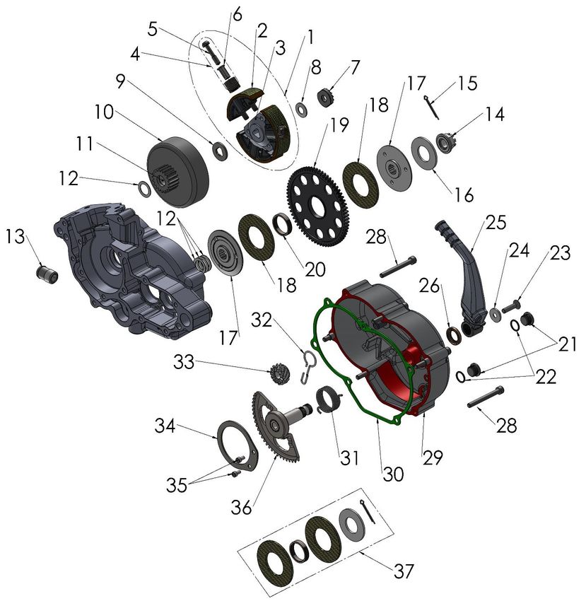
27Parts – Engine Clutch and Kick Lever
28Engine – Clutch and Kick Starter
REF # PART # DESCRIPTION
1 CAFW0500 CLUTCH COMPLETE ASSY - 5GX
2 CAFW0050 3 SHOES & WASHER STACKS W BOLTS - 5GX
3 CCMU0005 CLUTCH ARBOR – 3 SIDED SPLINE
4 CAFW0005 WASHER STACKS - SET OF 3 - CLUTCH - 5GX
5 HCBT0001 BOLT - TORX - 5GX CLUTCH - M6 X 29
6 CCMU0008 SLEEVE - CLUTCH STACK 5GX
7 ECMU0018 CLUTCH NUT, SPECIAL
8 ECDC0030 BELLEVILLE LOCK WASHER
9 CCMU0007 CLUTCH BACKING SPACER
10 ECMU0120 CLUTCH BASKET WITH NEEDLE BEARING
11 ECMU0119 CLUTCH BEARING
12 ECMU0040 CLUTCH TO HUB SPACER(S) (0.030”, 0.76mm)
13 ECMU0132 FITTING - COOLANT
14 ECMU0307 NUT V3 CFD
15 HCCP0002 COTTER PIN 3/32 X 1 ½”
16 ECMU0308 BELLEVILLE SPRING V3 CFD
17 ECMU0306 SLIP HUB V3 CFD (2) REQ’D
18 ECMU0249 FRICTION MATERIAL V3 CFDTHICK (2 REQ’D)
19 ECMU0301 GEAR V3 CFD
20 ECMU0305 BUSHING V3 CFD 7mm
21 ECMU0272BLK OIL FILL PLUG, BLK
22 ZCMUB014 O’RING – OIL FILL PLUG
23 HCFH0616 M6X16mm FLANGE HEAD BOLT
24 ECMU0250 WASHER – KICK LEVER MOUNTING
25 EAMU0011 KICK LEVER
26 ECDC0078 SEAL - KICKSHAFT
28 HCBC0608 M6X55mm SHCS (6 REQ’D)
29 ECMU0263 CLUTCH COVER ASSEMBLY WITH SEAL AND PIN
30 ZCMU0017 GASKET - CLUTCH COVER
31 ECMU0273 SPRING, KICKSTART
32 ECMUSP01 KICK START DOG SPRING (PAPER CLIP / ‘J’ SPRING)
33 ECMU0207 KICKSTART GEAR SMALL
34 ECMU0278 BRACKET – KICK SHAFT RETAINING
35 HCBC0508 M5 X 8mm SHCS (2 REQ’D)
36 ECMU0269 KICKSTART GEAR & SHAFT
KIT HKCP0001 10 PACK OF COTTER PINS (HCCP0002)
KIT EKMU0002 KICKSTART PIVOT KIT SPRING-BALL-SCREW
KIT HKAM0022 CLUTCH SHIM HARDEWARE KIT
37-KIT EKMU0033 CFD RFRESH KIT W’ FRICTIONS, SPRING, BUSHING AND COTTER PINS
TOOL MCMUTL40 TOOL - CFD – CHECK STOP PIN - VENOM
TOOL MCMUTL18 TOOL – SPROCKET SOCKET – HIGH TORQUE
TOOL ECMU0078 TOOL – SOCKET - CLUTCH NUT – CX50
TOOL MCMUTL03 TOOL – PISTON STOP
TOOL MCMUTL70 TOOL – PULLER – CLUTCH AND FLYWHEEL – CX50
29Parts – Engine – Water Pump
Engine – Ignition and Water Pump
REF # PART # DESCRIPTION
1 EKMU0021 WATER PUMP KIT
2 ECMU0265 SHAFT, WATER PUMP
3 ECKG0072 BEARING, WATER PUMP
4 ECKG0074 SEAL, WATER PUMP SHAFT
5 ECKG0073 IMPELLER, WATER PUMP (ALUMINUM)
6 HCBB0512 M5X12mm BUTTON HEAD
7 ECMU0167 BEARING – WATER PUMP BIG
8 EKMU0035P KIT – PULLEYS, SPACER & BELT RETAINER
9 HCBS0009 SHOULDER BOLT
10 ECKG0170 WATER PUMP BELT
11 HCBC0408 M4X8mm SOCKET HEAD CAP SCREW (2 PLACES)
12 HCWF0401 4MM FLAT WASHER
13 ECMU0274 COVER – WATER PUMP
14 HCBC0412 M4 X 12 SHCS (2 REQ’D)
TOOL MCMUTL20 TOOL – WATER PUMP INSTALL - VENOM
30Parts – Engine – Top End
Engine – Top End
REF # PART # DESCRIPTION
1 EKMU0361 CYLINDER KIT - (INCLUDES STUDS, PISTON, RINGS, PIN & CLIPS)
2 ZCMU0102 BASE GASKET (0.20mm) THICK
2 ZCMU0103 BASE GASKET (0.30mm) THICK
2 ZCMU0104 BASE GASKET (0.40mm) THICK
2 ZCMU0105 BASE GASKET (0.50mm) THICK
2 ZCMU0106 BASE GASKET (0.60mm) THICK
3 ECMU0276A PISTON KIT – ‘A’ SIZE (B, C, and D sizes available)
4 ECMU0077 BEARING, WRIST PIN
5 ECMU0155 PISTON RINGS (2 PER SET)
6 ECMUSR00 SNAP RING FOR PISTON (2 REQ'D)
7 ECKG0012 WRIST PIN
8 ZCMUOR07 O-RING, EXHAUST FLANGE
9 ECMU0262 EXHAUST FLANGE
10 ZCMOTE11 O-RINGS – PIPE TO FLANGE (2 REQ’D)
11 HCBC0612 M6X12, EXHAUST FLANGE SCREW (2 REQ'D)
12 HCNF0601 6MM FLANGE NUT (5 REQ’D)
13 ECC60149 CYLINDER HEAD OUTER
14 ZCC60009 O-RING, CYLINDER HEAD LARGE
15 ZCMUOR23 O-RING CYLINDER HEAD SMALL
16 ECMU0208 CYLINDER HEAD, INSERT
17 ZCMUOR05 O-RING CYLINDER HEAD MEDIUM - YELLOW
18 ZCMUOR03 O-RING CYLINDER STUD (5 REQ'D)
19 ECC60107 6MM STUD (5 REQ’D)
20 HCNF0801 8MM FLANGE NUT (4 REQ’D)
21 ECC60109 STUD, CYLINDER 8mm (4 REQ’D)
22 ECMU0010I SPARK PLUG, IRIDIUM AUTOLITE, XS61
23 EKMU0036 REBUILD KIT - TOP END - VENOM ENGINE - A PISTON
23 EKMU0037 REBUILD KIT - TOP END - VENOM ENGINE - B PISTON
23 EKMU0038 REBUILD KIT - TOP END - VENOM ENGINE - C PISTON
23 EKMU0039 REBUILD KIT - TOP END - VENOM ENGINE - D PISTON
ACCESSORY ZKMUOR13 TOP END O-RING KIT
EACS2021 COMPLETE VENOM ENGINE
31Parts – Exhaust System
Exhaust System
REF # PART # DESCRIPTION
1 XACS2021 EXHAUST PIPE
2 ZCMOTE11 HEADER PIPE O-RINGS (2 REQ’D)
3 XCMU0005 SPRING – EXHAUST (2 REQ’D)
4 XCMU0033 ISOLATION MOUNT
5 HCBF0616 M6X16mm FLANGE HEAD BOLT (2 REQ’D)
6 HCHA0003 6mm CLIP NUT – FOR FRONT PIPE MOUNT
7 XACS0001 SILENCER – 2021 KING
8 XCC60020 PIPE / SILENCER SEAL
9 MCMUGR03 MOUNTING GROMMET (2 REQ’D)
10 XCMU0051 SPACER (2 REQ’D)
11 HCBF0630 M6X30mm FLANGE HEAD BOLT (2 REQ’D)
12 MCMUGR08 GROMMET – SILENCER INDEXING
ACCESSORY XCMU0053 SILENCER PACKING KIT – 7”
32This Page Left Blank Intentionally
33Parts – Forks & Triple Clamps
34Front Forks and Triple Clamp
REF # PART # DESCRIPTION
1 KACS2021 FORK COMPLETE, BRAKE & NON-BRAKE SIDE
2 KCMU0035 FORK GUARD SET – 2021
3 HCSP0610BLK BOLT - FORK GUARD - BLACK (6 REQ’D)
4 KCMU0036 BRAKELINE CLAMP
5 HCSP0004 PLASTIC SCREW (2 REQ’D)
6 FACS0009BLK TRIPLE CLAMP BOTTOM ASSY, (CLAMP & STEM) BLACK
7 FCMU0071BLK TRIPLE CLAMP TOP - BLACK
8 FCMU0074 BOLT – STEERING STEM
9 FCMU0079 DUST COVER (1 REQ’D)
10 FCMU0044 O-RING (1 REQ’D)
11 FCMU0004 STEERING HEAD BEARING (2 REQ’D)
12 HCBC0625 M6X25mm SOCKET HEAD CAP SCREW
13 HCBF0616 M6X16mm FLANGE HEAD BOLT (NUMBER PLATE & FENDER)
14 HCBC0825 M8 x 25mm SOCKET HEAD CAP SCREW
15 FCMU0011 RACE – STEERING STEM BEARING (2 REQ’D)
16 HCBC0602 M6X20MM SOCKET HEAD CAP SCCREW (2 REQ’D)
17 HCBC0806 M8x 30 SHCS
18 FCMU0170 STEERING STOP BUMPER (2 REQ’D)
19 HCBC0412 M4x 12mm SOCKET HEAD CAP SCREW
ACCESSORY FKMU0008 KIT – STEERING STEM BEARINGS, RACES AND SEALS
TOOL MCMUTL44 TOOL – BEARING AND SEAL INSTALLER ASSY
35Parts – Forks – Leg Assembly – Brake Side
36Parts – Forks – Leg Assembly – Brake Side
REF # PART # DESCRIPTION
1 HCBC0408 4 X 8 SHCS CLEAR ZINC
2 ZCKG0001 GASKET, BLEED SCREW FORK
3 KCCS0004C FORK CAP - CONVENTIONAL 32MM USD
4 ZCMUOR18 O-RING – 3MM X 27MM ID
5 KCCS0036 SPRING WEAR PLATE 32MM
6 KCCS0005 OUTER TUBE 32MM
7 KCCS0035 RING CLIP FORK OUTER WEAR RING 32MM
8 KCCS0006 FORK GLIDE RING BOTTOM 32MM
9 KCCS0032 FORK SEAL SPACER 32MM
10 KKCS0004 FORK SEAL AND SWIPER KIT 32MM
11 KCCS0002 RING CLIP - FORK SEAL RETAINER - 32MM
12 KCC60067 FORK JOUNCE BUMPER
13 KCCS0013 FORK SPRING GUIDE 32MM
14 KCCS3225 STANDARD SPRING - FORK 0.25 KG/MM 32mm
14 KCCS3223 LIGHT SPRING - FORK 0.23 KG/MM 32mm
14 KCCS3227 HEAVY SPRING - FORK 0.257KG/MM 32mm
15 HCNJ3824 NUT JAM 3/8-24 CLASS 8
16 KCC60068 RING CLIP - FORK SPRING GUIDE RETAINER
17 KAC60003 DAMPER ROD ASSEMBLY
18 KCC60058 O-RING MID-VALVE ADJ NEEDLE
19 KCC60050 FORK MID-VALVE ADJUSTER NEEDLE
20 KCC60051 SPRING - FORK ADJUSTER NEEDLE
21 KCCS0018 SEAL - FORK PISTON - MID VALVE
22 HCNJ0601 6MM JAM NUT
23 BCKG0033 O-RING – 2MMID
24 KCCS0033 ADJUSTER SCREW TOP 32MM
25 KCC60049 ADJUSTER PIN
26 KCMU0013 CARTRIDGE CAP
27 KCKG0050 TOP OUT SPRING
28 KCKG0019 CARTRIDGE TUBE
29 KCMU0021 O-RING - FORK - BASE VALVE
30 ZCKGB017 O-RING - FORK BOTTOM PLUG
31 KCC60069 FORK BOTTOM PLUG – ADJUSTABLE
32 KCC60048 ADJUSTMET SCREW – FORK BOTTOM PLUG
33 ZCMUOR03 O-RING – ADJUSTMENT SCREW
34 KCCS0031 RING CLIP – FORK ADJUSTMENT SCREW
35 KCCS0007 FORK GLIDE RING
36 KAMU0003 FOR LOWER – COMPLETE – BRAKE SIDE
TOOL MCMUTL39 TOOL – FORK SEAL / SWIPER DRIVER – 32MM
TOOL MCMUTL32 TOOL – FORK CAP WRENCH – 32MM
TOOL MCMUTL04 TOOL – CARTRIDGE TUBE WRENCH
37Parts - Forks – Leg Assembly – Non-brake Side
38Parts - Forks – Leg Assembly – Non-brake Side
REF # PART # DESCRIPTION
1 HCBC0408 4 X 8 SHCS CLEAR ZINC
2 ZCKG0001 GASKET, BLEED SCREW FORK
3 KCCS0004S FORK CAP - CONVENTIONAL 32MM USD
4 ZCMUOR18 O-RING – 3MM X 27MM ID
5 KCCS0036 FORK - SPRING WEAR PLATE 32MM
6 KCCS0005 FORK - OUTER TUBE 32MM
7 KCCS0035 RING CLIP FORK OUTER WEAR RING 32MM
8 KCCS0006 GLIDE RING BOTTOM 32MM
9 KCCS0032 SEAL SPACER 32MM
10 KKCS0004 FORK SEAL AND SWIPER KIT 32MM
11 KCCS0002 RING CLIP - FORK SEAL RETAINER - 32MM
12 KCC60067 FORK JOUNCE BUMPER
13 KCCS0013 SPRING GUIDE 32MM
14 KCCS3225 STANDARD SPRING - FORK 0.25 KG/MM 32mm
14 KCCS3223 LIGHT SPRING - FORK 0.23 KG/MM 32mm
14 KCCS3227 HEAVY SPRING - FORK 0.257KG/MM 32mm
15 HCNJ3824 NUT JAM 3/8-24 CLASS 8
16 KCC60068 RING CLIP - FORK SPRING GUIDE RETAINER
17 KAC60003 DAMPER ROD ASSEMBLY
18 KCC60058 O-RING MID-VALVE ADJ NEEDLE
19 KCC60050 FORK MID-VALVE ADJUSTER NEEDLE
20 KCC60051 SPRING - FORK ADJUSTER NEEDLE
21 KCCS0018 SEAL - FORK PISTON - MID VALVE
22 HCNJ0601 6MM JAM NUT
23 BCKG0033 O-RING – 2MMID
24 KCCS0033 ADJUSTER SCREW TOP 32MM
25 KCC60049 ADJUSTER PIN
26 KCMU0013 CARTRIDGE CAP
27 KCKG0050 TOP OUT SPRING
28 KCC60056 CARTRIDGE TUBE
29 KCMU0021 O-RING - FORK - BASE VALVE
30 KCC60057 PLUG – FORK BOTTOM – SMART LEG
31 KCCS0007 FORK GLIDE RING
32 KAMU0004 FOR LOWER – COMPLETE – NON BRAKE SIDE
TOOL MCMUTL39 TOOL – FORK SEAL / SWIPER DRIVER – 32MM
TOOL MCMUTL32 TOOL – FORK CAP WRENCH – 32MM
TOOL MCMUTL04 TOOL – CARTRIDGE TUBE WRENCH
39Parts – Frame I
Frame
REF # PART # DESCRIPTION
1 FACS2021 FRAME – 2021 KING & FWE
2 HCHA0003 6mm CLIP NUT (MOUNTS TO FENDER TO HOLD SEAT)
3 MCMUGR12 GROMMET, RADIATOR MOUNTING (4 REQ’D)
4 GCMU0022 BOLT - TI - SWINGARM PIVOT and AXLE - CX50
5 HCNL1201 M12 SWINGARM LOCK NUT
6 HCBH0880 M8X80mm HEX HEAD BOLT
7 HCNL0801 M8 LOCK NUT
8 TAMU0139 FOOTPEGS (PAIR)
9 FCMU0031 CLEVIS PIN - FOOTPEG
10 HCWF0801 8mm FLAT WASHER
11 HCCP0008 COTTER PIN 1/8 X 3/4
12 XCMU0033 ISOLATION MOUNT – EXHAUST
13 HCBF0616 M6X16mm FLANGE HEAD BOLT (2 REQ’D)
14 BCMU0027 BRAKE PEDAL PIVOT BOLT
15 HCSP0610 LARGE HEAD SHOULDERED BOLT
16 HCBC0675 M6x 75 SHCS ZINC
17 HCWF0601 M6 FLAT WASHER
18 TCHA0006 BUSHING - FUEL TANK
19 TCMU0017 BUSHING – FUEL TANK - SQUARE
20 HCBF1040 M10x 40 HEX HEAD BOLT
21 HCSP0701 SPROCKET BOLT – M7
22 FCMU0109 COMPRESSION LIMITER – SUB FRAME
23 HCNK0601 M6 LOCKNUT
24 HCBC06SP BRAKE ADJUSTER BOLT
25 HCBC0601 M6x 16 SHCS
26 TCMU0044 LOWER CHAIN SLIDE
ACCESSORY TCMU0106 FOOTPEG SPRING (SINGLE PIECE)
40Parts – Frame II
Frame
REF # PART # DESCRIPTION
1 FACS0010 SUBFRAME 2021
2 HCBC0603 M6X30mm SOCKET HEAD CAP SCREW FT TANK MOUNTING
3 HCBC0520 M5X20mm SOCKET HEAD CAP SCREW (2 REQ’D)
4 HCCN0001 5mm CLIP NUT
5 HCBC0516 M5X16mm SHCS
6 TCC60017 WASHER - BODY PANEL FLAT (2 REQ’D)
7 MCMUGR03 MOUNTING GROMMET (2 REQ’D)
8 XCMU0051 SPACER AND COMPRESSION LIMITER(2 REQ’D)
9 HCBC0602 M6X20mm SHCS
10 FCMU0109 COMPRESSION LIMITER – SUB FRAME – (2 REQ’D)
11 HCSP0701 SPROKET BOLT – 3(REQ’D)
12 HCBC0650 M6X50mm SOCKET HEAD CAP SCREW
13 TCC60018 SEAT MOUNT SPACER
14 HCHA0003 M6 CLIP NUT
15 HCSP0610 LARGE HEAD SHOULDERED BOLT
16 ICMU0044 IGNITION COIL
41Parts – Front Brakes
11
Front Brakes
REF# PART # DESCRIPTION
1 BACS0001 BRAKE ASSY - FRONT CARD - KING FW - 2 PISTON 9.5
2 BCCS0003 HOSE – BRAKE FRONT
3 BAMU0009 LEVER ASSEMBLY – THIN FORMLY
4 BAMU0006 MASTER CYLINDER ASSEMBLY COMPLETE W LEVER
5 BAMU0020 CALIPER – FRONT – CARD 2 PISTON
6 BKMU0009 KIT 505 ORGANIC BRAKE PADS, WITH BOLT AND CLIP
7 BCMU0222 BRAKE ROTOR
8 HCBC0514 M5X14mm SOCKET HEAD CAP SCREW (5 REQ’D)
9 HCBC0604 M6X35mm SOCKET HEAD CAP SCREW
10 HCBC0602 M6X20mm SOCKET HEAD CAP SCREW
11 BCMU0116 COVER – MUD PROTECTION
Caliper Accessories
ACCESSORY MCMUBF03 BRAKE FLUID – SPECTRO DOT4 RACING –HIGH TEMP - 355 ml
ACCESSORY BKMU0003 BLEED KIT (MULTIPLE SYRINGES, FITTINGS & HOSE)
ACCESSORY BCMU0038 SPRING - BRAKE PAD RETURN
ACCESSORY BKMU0006A PISTON & SEAL KIT – CARD CALIPER - ALUMINUM
ACCESSORY BKMU0008 BLEED SCREW KIT – CARD
ACCESSORY BKMU0007 BANJO BOLT AND WASHER KIT – CARD
ACCESSORY BCMU0014 CALIPER ADJUSTMENT SHIMS 6mm ID
Master Cylinder Accessories
ACCESSORY BKC60008 CAP & BLADDER KIT ZL150
(CAP, BLADDER & (2) M3-0.5 X 6mm LONG PHILLIPS SCREW)
ACCESSORY BCC60058 CLAMP – M/C ZL150
ACCESSORY HCBC0602 M6-1.0 X 22mm SOCKET HEAD CAP SCREW
ACCESSORY BCMU0060 PIVOT BOLT
ACCESSORY BCC60017 BOOT – PISTON END COVER
ACCESSORY BKMU0010 REBUILD KIT – MASTER CYLINDER CARD 9.5MM
ACCESSORY (PISTON, SEALS, BUSHING, SPRING, CLIIP & RETAINING WASHER)
ACCESSORY HCSS0520 M5 X 20 SET SCREW – LEVER POSITON ADJUSTMENT
ACCESSORY HCNJ0501 5MM LOCKNUT
ACCESSORY CKC60005 PIVOT BOLT KIT – LEVER TO PIVOT BLOCK – MALE & FEMALE
ACCESSORY HCSS0610 SET SCREW – PRESET
ACCESSORY BCMU0059 LEVER ONLY – THIN FORMLY
ACCESSORY CCC60026 SPRING – LEVER RETURN
ACCESSORY CCC60025 SPACER – SPRING CENTERING
42Parts – Front Wheel
Front Wheel
REF # PART # DESCRIPTION
1 WACSF021BLK WHEEL WITH BEARINGS SPOKE STYLE – BLACK ANODIZE
2 WCMU0043 FRONT AXLE - HOLLOW
3 HCSP1016BLK BOLT – ALUMINUM AXLE PULL – BLACK ANODIZE
4 WCMU0024 PLUG - BLACK PLASTIC
5 HCBC0514 M5X14mm SOCKET HEAD CAP SCREW (5 REQ’D)
6 BCMU0222 BRAKE ROTOR – FRONT & REAR
7 WCMU0045 WHEEL SPACER LEFT
8 WCMU0120 BEARING – WHEEL (2 REQ’D)
9 WCMU0044 SPACER – WHEEL FRONT
10 WCKG1201 TUBE 12”
11 WCKG1200D32 TIRE - FRONT - 60/100-12- DUNLOP MX3S
43You can also read