Condensed Matter and Interphases - Voronezh State ...
←
→
Page content transcription
If your browser does not render page correctly, please read the page content below
Condensed Matter and Interphases. 2021;23(3): 396–405
ISSN 1606-867Х (Print)
ISSN 2687-0711 (Online)
Condensed Matter and Interphases
Kondensirovannye Sredy i Mezhfaznye Granitsy
https://journals.vsu.ru/kcmf/
Original articles
Research article
https://doi.org/10.17308/kcmf.2021.23/3531
TSF-MOCVD – a novel technique for chemical vapour deposition
on oxide thin films and layered heterostructures
A. R. Kaul1, R. R. Nygaard1, V. Yu. Ratovskiy1, A. L. Vasiliev2,3,4 *
1
Lomonosov Moscow State Univеrsity,
1 Leninskie Gory, Moscow 119991, Russian Federation
2
National Research Center “Kurchatov University”,
1 pl. Akademika Kurchatova, Moscow 123182, Russian Federation
3
Shubnikov Crystallography Institute of the Russian Academy of Sciences,
59 Leninskiy prospect, Moscow 119333, Russian Federation
4
Moscow Institute of Physics and Technology,
9 Institutskiy Pereulok, Moscow Region, Dolgoprudny, 141701, Russian Federation
Abstract
A new principle for supplying volatile precursors to MOCVD gas-phase chemical deposition systems is proposed, based on
a two-stage evaporation of an organic solution of precursors from a soaked cotton thread, which passes sequentially through
the zones of evaporation of the solvent and precursors. The technological capabilities of TSF-MOCVD (Thread-Solution
Feed MOCVD) are demonstrated based on examples of obtaining thin epitaxial films of СеО2, h-LuFeO3 and thin-film
heterostructures β-Fe2O3/h-LuFeO3. The results of studying the obtained films by X-ray diffraction, energy dispersive X-ray
analysis, and high- and low-resolution transmission microscopy are presented. Using the TSF module, one can finely vary
the crystallisation conditions, obtaining coatings of the required degree of crystallinity, as evidenced by the obtained
dependences of the integral width of the h-LuFeO3 reflection on the film growth rate. Based on the TEM and XRD data, it
was concluded that β-Fe2O3 grows epitaxially over the h-LuFeO3 layer. Thus, using TSF-MOCVD, one can flexibly change
the composition of layered heterostructures and obtain highly crystalline epitaxial films with a clear interface in a continuous
deposition process.
Keywords: Thread-solution feed, TSF, MOCVD, Epitaxy, Thin films, Heterostructures
Acknowledgements: the work was carried out within the framework of project No 19-33-90289 supported by Russian
Foundation for Basic Research.
For citation: Kaul A. R., Nygaard R. R., Ratovskiy V. Yu., Vasiliev A. L. TSF-MOCVD – a novel technique for chemical vapour
deposition on oxide thin films and layered heterostructures. Kondensirovannye sredy i mezhfaznye granitsy = Condensed
Matter and Interphases. 2021;23(3): 396–405. https://doi.org/10.17308/kcmf.2021.23/3531
Для цитирования: Кауль А. Р., Нигаард Р. Р., Ратовский В. Ю., Васильев А. Л. TSF-MOCVD – новый способ осаждения
оксидных тонких пленок и слоистых гетероструктур из газовой фазы. Конденсированные среды и межфазные границы.
2021;23(3): 396–405. https://doi.org/10.17308/kcmf.2021.23/3531
Roy Nygaard, e-mail: rnygaard@mail.ru
© Kaul A. R., Nygaard R. R., Ratovskiy V. Yu., Vasiliev A. L., 2021
The content is available under Creative Commons Attribution 4.0 License.
396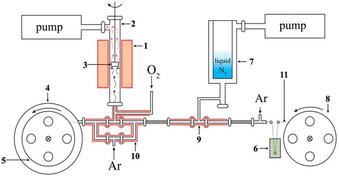
Condensed Matter and Interphases / Конденсированные среды и межфазные границы          2021;23(2): 396–405
 A. R. Kaul et al.                        TSF-MOCVD – a novel technique for chemical vapour deposition...

    1. Introduction                                    feed of precursors into the reactor. However,
    Thin-film technologies underlie the                it is important to understand that the total
development of many scientific and technical           concentration of precursor solutions is usually
fields, and their continuous improvement gives         in the order of 10–1 M, from which it follows that
rise to new possibilities for creating modern          the vapour in the reactor is formed mainly by the
materials and thin-film devices with a precisely       organic solvent. The solvent vapour, as well as
specified architecture and physical properties.        the vapour of the precursors, undergoes pyrolysis
Along with high-vacuum physical methods                and oxidation near the substrate heated to a high
for producing thin films, chemical vapour              temperature, which increases the concentration
deposition (CVD) is widely used. [1–3]. Thus,          of residual carbon in the films, reduces and makes
the MOC-hydride epitaxy method has taken a             the partial pressure of oxygen in the deposition
leading position in the production of planar           zone undefined [14]. It is clear that this method
semiconductor structures A III B V , A II B VI and     is of little use for the reproducible production
solid solutions based on them [4], and metal-          of films of easily reducible oxides, oxides with
organic precursor vapour deposition (MOCVD)            a narrow region of oxygen homogeneity, and
is successfully used to obtain a wide range of         other films with functional properties sensitive
oxide coatings, as well as in the development          to residual carbon.
of functional materials for oxide electronics [5].         MOCVD systems, in which the reactor is fed
The MOCVD method started to be intensively             by the flash evaporation of micro-portions of a
developed at the end of the 80s of the last century    mixture of solid precursors, are free from these
due to the need to obtain thin HTSC films [6]. Over    fundamental disadvantages. [12, 15], however,
the years, this method has been demonstrated           instead of them, there are problems with the
to be extremely flexible in producing films of         uniformity of vapour supply to the reactor and
a wide variety of compositions and purposes,           the limited amount of precursor substances
as well as the ability to deposit coatings with        loaded into the feeder of the setup for a single
high uniformity and over large areas. [7]. Both        experiment. The disadvantages of this approach
highly-crystalline epitaxial functional layers         in the implementation of the MOCVD process
and heterostructures with clear interfaces             also include the technical complexity of setups,
with a thickness of several nanometres [8], and        especially those designed specifically for the
polycrystalline coatings with a thickness of tens      production of thin-film heterostructures. [16, 17].
of microns can be obtained using MOCVD [9].                This article highlights a new principle
    In the deposition of multicomponent films,         of supplying liquid precursors to chemical
along with the traditional approach, which             vapour deposition systems, which combines
consists in the evaporation/sublimation of the         the advantages of known liquid-phase and solid
precursor of each component from an individual         state power supply systems and is devoid of their
source heated to the required temperature [7], a       disadvantages [18]. Moreover, it allows obtaining
more convenient single source is used successfully     thin-film structures consisting of layers of
[10, 11]. In this case, the mixture of precursors is   different chemical compositions within a single
sharply heated to a temperature providing the          deposition run, as well as thin films with a vertical
simultaneous transition of all precursors into         composition gradient.
a vapour, including the least volatile of them.
This approach can be implemented in two ways,          2. Experimental
which differ in the aggregate states of the mixture        All samples were obtained using MOCVD
of precursors: either an aerosol of an organic         setup with TSF module for precursor feed and
solution of a mixture of precursors [10, 11], or a     a vertical hot-walled reactor. The scheme of
fine mechanical mixture of solid precursors are        MOCVD setup with TSF module, in which the new
used [12, 13]. Both schemes have advantages and        principle was applied, is shown in Fig. 1. During its
disadvantages. For example, liquid-phase MOCVD         operation, the following stages were carried out:
systems are technically simpler than solid state       a cotton thread (11) passed through a solution
systems and provide a continuous and smoother          of precursors in a low-boiling solvent (6), which

                                                                                                        397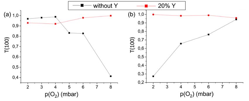
Condensed Matter and Interphases / Конденсированные среды и межфазные границы                     2021;23(2): 396–405
  A. R. Kaul et al.                           TSF-MOCVD – a novel technique for chemical vapour deposition...

Fig. 1. The scheme of MOCVD setup with TSF module, 1 – reactor furnace, 2 – quartz reactor, 3 – substrate
holder, 4 – vacuum container for the receiving reel, 5 – receiving reel, 6 – precursor reservoir, 7 – nitrogen trap,
8 – feeding reel, 9 – cold zone of the TSF module, 10 – hot zone of the TSF module, 11 – cotton thread

evaporated in the solvent distilling zone (9). After       solution, or the speed of drawing the thread, or
distilling off the solvent, the thread, covered with       the absorption capacity of the thread.
small crystals of precursors, continued to move                The described setup was used to synthesize
towards the hot zone (10), where the precursors            the following objects:
were sublimated, and the resulting vapours                     a) epitaxial CeO2 thin films on R-sapphire,
were transferred to the reactor (2) by heated                  b) epitaxial hexagonal LuFeO3 (h-LuFeO3)
argon flow. Directly at the inlet to the heated            thin films on the (111) and (100) surfaces of YSZ
quartz reactor, oxygen was introduced into the             single-crystal,
gas mixture of argon with precursor vapours                    c) thin-film heterostructures with an
in a predetermined proportion. In the reactor              architecture of b-Fe2O3(100)//h-LuFeO3 (001)//
zone, the precursor vapours decomposed in the              YSZ(100) and b-Fe2O3 (111)//h-LuFeO3 (001)//
substrate zone, which led to the formation of a            YSZ(111).
thin oxide film. Throughout the entire deposition,             Metal-organic volatile complexes of
the substrate holder (3) was rotated constantly for        Ce ( t h d ) 4 , L u ( t h d ) 3 a n d F e ( t h d ) 3 ( t h d =
a more uniform heating and a more symmetrical              2,2,6,6-tetramethylheptanedionate 3,5) dissolved
arrangement of the substrates with respect to              in toluene were used as precursors. In all cases,
the gas flow directed along the normal to their            a temperature of 190 °C was set in the hot zone
surface.                                                   of the TSF module (10) for sublimation of the
    During the entire deposition process, the              precursors. CeO2 thin films were deposited at
reservoir with the precursor solution was                  temperatures of 850 and 900 °C in the reactor. The
outside the vacuum system and was accessible               total pressure in the reactor was 10 mbar and the
to the experimenter, therefore, by replacement             partial pressure of oxygen in the reactor was 2, 3,
of the solution in the reservoir (6), one could            4, 5, 6, and 8 mbar. The depositions were carried
optionally change the chemical composition of              out on single-crystalline r-sapphire with a surface
the deposited oxide layers by gradual addition of          orientation (10–12), which before deposition
additional precursors. It allowed to control the           were annealed at a temperature of 900 °C for
structure of the interface, making the transition          30 min for the purification of the surface from
between phases either abrupt or smooth,                    the residues of adsorbed organic contaminants.
depending on the task. The proposed scheme                     The molar ratio of precursors (Lu:Fe) in
also allowed the extremely fine variation of the           a toluene solution varied from 1 to 2 for the
film growth rate, which is an important condition          production of h-LuFeO3 single-phase thin films
for crystallisation. It can be changed by altering         of the required stoichiometry. It has been found
either the concentration of precursors in the              that the optimal Lu:Fe ratio in the solution is 2.

398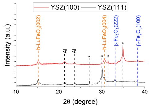
Condensed Matter and Interphases / Конденсированные среды и межфазные границы                                     2021;23(2): 396–405
 A. R. Kaul et al.                        TSF-MOCVD – a novel technique for chemical vapour deposition...

h-LuFeO3 thin films were obtained at a reactor         is directed along the normal to the substrate
temperature of 900 °C, a total pressure in the         plane, and in the other, the [111] axis is oriented
reactor of 10 mbar and the oxygen partial pressure     in this direction. The [100] orientation is
in the reactor of 1 mbar. The deposition was           thermodynamically more favourable, since the
carried out on single-crystalline YSZ [ZrO2(Y2O3)]     R-plane of the sapphire has a rectangular motif,
substrates with the (111) and (100) orientations       which promotes the growth of the cubic CeO2
of the growth surface. Before deposition, these        face. The growth in the [111] direction is due
substrates were annealed in air at a temperature       to kinetic reasons: as is known, this direction
of 1100 °C for 24 h, while the defects in the          is the direction of the rapid growth of crystals
structure of the surface layer, damaged by the         with a fluorite structure. Our goal was to achieve
polishing of the substrates by the manufacturer,       the growth of films in which the fraction of
were eliminated.                                       (100)-oriented crystallites is maximal. The key
    Deposition of b-Fe2O3 layers on the h-LuFeO3       condition for success in this case is fast surface
buffer layers was carried out at a temperature in      diffusion, which promotes the crystallisation
the reactor of 900 °C, the total pressure in the       of the thermodynamically favourable (100)
reactor of 10 mbar, and the partial pressure of        orientation. For acceleration of the surface
oxygen in the reactor of 0.1 mbar.                     diffusion, two ways were used: the first was an
    The epitaxial growth of all films and layers was   increase in the deposition temperature, and the
confirmed by X-ray diffraction (2q-w scanning)         second was the heterovalent doping of CeO 2
using a Rigaku Miniflex diffractometer with            films with yttrium oxide. In the second case,
a copper anode (lKa = 1.54046 Å), a power of           diffusion is activated due to the appearance of
600 W, and a beta filter. The cationic composition     oxygen vacancies in the growing film.
of h-LuFeO3 films was determined by energy                 The texture coefficient (T) of the (100)
dispersive X-ray analysis using a Carl Ziess Leo       orientation, calculated by equation (1), which
SUPRA 50 VP scanning electron microscope               allows estimating its share among all other
with an X-ray system (Oxford Instruments INCA          orientations, taking into account the structural
Energy+).                                              data was used as a quantitative characteristic of
    Cross sections of b-Fe 2O 3/h-LuFeO 3/YSZ          the quality of the obtained films.
thin-film heterostructures were prepared for                                        200           400
                                                                                  I exp         I exp
transmission electron microscopy using a                                                    +
focused ion beam (FIB) on a Helios Nanolab 660                                    I st200       I st400
                                                       T (100 ) =                                                       .         (1)
scanning electron microscope (ThermoFisher                            200
                                                                    I exp            400
                                                                                  I exp           111
                                                                                                I exp           222
                                                                                                              I exp
Scientific, USA) equipped with an Omniprobe                                   +             +             +
                                                                    I st200       I st400       I st111       I st222
micromanipulator (Omniprobe, USA). The cut
lamellae were examined using a Titan 80-300                For the calculation, we used the intensities
TEM/STEM device (FEI, USA) equipped with a             of the (100) and (111) reflections in the obtained
CS corrector at an accelerating voltage of 300 kV.            ( )hkl
                                                       films I exp    determined by profile analysis of
The microscope is equipped with an EDX Si              the corresponding reflections, as well as their
(Li) spectrometer (EDAX, USA), a high angular          reference intensities taken from the powder
annular dark-field detector (HAADF) (Fischione,        diffractogram stored in the crystallographic data
USA), and a Gatan Image Filter (GIF) (Gatan, USA).     base. Thus, the closer the texture coefficient is
                                                       to 1, the more grains in the film are oriented with
3. Results and discussion                              the (100) plane parallel to the substrate plane,
3.1. СеО2 thin films                                   and the more perfect is the film.
    Epitaxial CeO2 thin films are a very popular           It can be seen, that the character of the texture
material with multiple applications; in                coefficient dependence upon the oxygen partial
particular, they are used as a buffer layer in         pressure changes dramatically with an increase in
the deposition of HTS films. CeO2 can grow in          temperature: at 850 °C the trend was downward
two different orientations on R-sapphire: in           (black line in Fig. 2a), while at 900 °C (black line
one of them, the crystallographic axis [100]           in Fig. 2b) it changed to an upward trend.

                                                                                                                                 399
Condensed Matter and Interphases / Конденсированные среды и межфазные границы 2021;23(2): 396–405
A. R. Kaul et al. TSF-MOCVD – a novel technique for chemical vapour deposition...
Fig. 2. Dependence of the texture orientation coefficient (100) of СеО2 on p(O2) and the content of the doping
component (yttrium oxide) at the deposition temperature a) 850 °С and b) 900 °С
This fact can be explained as follows: at 850 °C, the concentration of which is many orders of
an increase in p(O2) increased the deposition rate magnitude higher than the equilibrium concen-
making the surface diffusion flow insufficient, tration of thermal vacancies, which, in turn,
which led to the formation of a larger proportion leads to a sharp increase of the surface diffusion
of grains with the (111) orientation. The rate of flow. As a consequence, the dependence of the
surface diffusion exponentially depends on the texture coefficient (red line in Figs. 2a and 2b),
temperature and at a temperature of 900 °C it both on the partial pressure of oxygen and on
already becomes sufficient for the equilibrium temperature, disappears, since under any depo-
crystallisation of the film from the substance sition conditions implemented in this study,
approaching the substrate surface. However, at the system has sufficient diffusion mobility to
this temperature, the system approaches pO2-T reach the most energetically favourable (ther-
conditions for the dissociation of CeO2, and phase modynamically stable) variant of film growth.
stabilization of this oxide requires an increase in This result confirms the conclusions of the
pO2. Dissociation occurs with the formation of an study [21].
equilibrium Се7О12 [19] phase which crystallises
3.2. h-LuFeO3 thin films
in the rhombohedral space group R3,c unit cell
parameter a = 6.785 (1) Å and angle a = 99.42 (1) Thin films of h-LuFeO3 were more complex
[20]. The emergence of the secondary phase nuclei object obtained using the proposed precursor
limits the epitaxial growth of the main СеО 2 feed method. It should be noted that under the
phase in the equilibrium (100) orientation, as a conditions of conventional solid state synthesis,
result of which the (111) orientation and other LuFeO 3 crystallises with orthorhombically
polycrystalline orientations develop. This should distorted perovskite structure [22]. Formation
be prevented by increasing the pO2 in the reactor. of the hexagonal ferrite LuFeO3, which is
As we noted above, the second method for isostructural to the hexagonal manganite LuMnO3,
activating of surface diffusion to facilitate the becomes possible due to epitaxial stabilization on
achievement of the thermodynamic equilibrium a structurally coherent substrate [23]. The low
is the heterovalent doping of cerium oxide with energy of the film – substrate interface leads to
yttrium oxide, which leads to the formation of a decrease in the free energy of the system and
oxygen vacancies in the films: the stabilization of phases structurally coherent
to the substrate and unstable in the autonomous
1 3 1 state [24]. In this study, YSZ(111) and YSZ(100)
¢ + OO¥ + VO ,
Y2O3( ÆCeO2 ) = YCe
2 2 2 were used as such substrates.
400Condensed Matter and Interphases / Конденсированные среды и межфазные границы 2021;23(2): 396–405
A. R. Kaul et al. TSF-MOCVD – a novel technique for chemical vapour deposition...
For demonstration of the possibility of An interesting feature is that the integral
controlling the crystallisation conditions using width of the h-LuFeO3 reflection formed on the
the new precursor feed system, a series of YSZ(100) surface in all cases was higher than that
depositions were carried out, varying the film of h-LuFeO3 on the YSZ(111) surface. The reason
growth speed by changing the thread passing for this may be that the stabilizing effect of the
speed. The X-ray diffraction results (Figs. 3a (100) surface on h-LuFeO3 is lower than that
and 3b) showed that in all cases the films are for the (111) surface due to the lower structural
h-LuFeO3. correspondence of the YSZ(100) surface to
As can be seen from the dynamics of changes the hexagonal crystal structure of the forming
in the integral width of (002) reflection of the film(25).
h-LuFeO3 (Fig. 4), the crystallinity of the films
3.3. Thin-film heterostructures
decreased with an increase in the growth rate,
h-LuFeO3+b-Fe2O3
which is quite a logical observation. In this case,
a decrease in crystallinity can be associated The possibility of the deposition of
not only with an insufficiently active surface layers of various chemical compositions was
diffusion flux, but also with a deviation of the demonstrated on the example of obtaining thin-
system from the required stoichiometry Lu: Fe film heterostructures h-LuFeO3 with iron oxide
= 1: 1, leading to the formation of secondary on single-crystalline substrates YSZ(111) and
phases enriched in iron and interfering the YSZ(100). It can be seen from the diffraction
epitaxial growth of h-LuFeO3. Their reflections patterns (Fig. 5) that the iron oxide layer growing
can not be seen on the presented XRD patterns on top the h-LuFeO3 surface is an unusual cubic
probably due to absence of the clearly defined modification b-Fe2O3. It should be noted that
growth direction. this phase is unstable under the implemented
synthesis conditions. There is information in the
literature on its transition to a-Fe2O3 already at
650 ºC [26], while in this study, the deposition
temperature of the iron oxide layer was 900 ºC.
The absence of phases other than b-Fe2O3 and the
presence of only one family of reflections of this
phase indicated the strong epitaxial stabilization
of b-Fe2O3 by the h-LuFeO3 sublayer. It should be
noted that epitaxial stabilization also changes
the equilibrium characteristic phase relations
between Fe2O3 and LuFeO3: it is well known that
in mixtures of powders of this and similar systems
Fig. 3. Diffraction patterns of h-LuFeO3 films obtained Fig. 4. Dependence of the integral width of the
at different deposition rates on (a) YSZ (111) and (b) h-LuFeO3 (002) reflection on the deposition rate
YSZ (100) substrates
401Condensed Matter and Interphases / Конденсированные среды и межфазные границы 2021;23(2): 396–405
A. R. Kaul et al. TSF-MOCVD – a novel technique for chemical vapour deposition...
closer examination of images of heterostructure
b-Fe2O3(001)//h-LuFeO3(001)//YSZ(100) revealed
that h-LuFeO3 had not formed located uniformly
in one direction: its (001) planes were aligned
parallel to both (001) and (111) planes of the YSZ
substrate. The former growth variant is observed
near the substrate surface and continues up to
film thickness of roughly 25 nm where the growth
direction is switched to the later variant. The
presence of the side orientation of h-LuFeO3 in
the YSZ(100) heterostructure is very interesting
and can be a factor explaining the difference in
the growth direction of the b-Fe2O3 on different
Fig. 5. Diffraction patterns of thin-film b-Fe2O3/ substrates. Thus, in the heterostructure on
h‑LuFeO3 heterostructures on YSZ (111) and YSZ (100) YSZ(111) substrate the stabilizing surface for
substrates. Reflexes of substrates are marked with *
b-Fe2O3 is h-LuFeO3 with its (001) plane parallel
to the substrate plane while in case of YSZ(100)
(REE = Nd–Yb), Fe2O3, and RFeO3 REE oxides substrate b-Fe2O3 is stabilized on h-LuFeO3 with
react with each other forming garnet phases [27]. its (001) plane inclined by 54.7o relative to
However, thanks to the epitaxial contact of thin the substrate plane (54.7 is the angle between
films of these substances, the chemical reaction and directions in the cubic cell).
was suppressed. Similar changes in phase This substantiation of the b-Fe2O3 growth is also
relations as a result of epitaxial stabilization reinforced by the fact that the angle between
have been described for other oxide systems as the crystallographic directions of b-Fe2O3 in
well [24]. heterostructures on different substrates (
Also, the difference in the orientation of on YSZ(111) and on YSZ(100)) is also 54.7°.
the epitaxially growing b-Fe 2O3 film on YSZ Grains of b-Fe2O3 with clearly visible grain
surfaces with different indices should be noted: boundaries are clearly seen on microphotographs
in the heterostructure deposited on the YSZ(111) of heterostructures deposited on both substrates,
substrate, the oriented growth of the b-Fe2O3 which indicates Volmer–Weber type (island)
phase was observed in the [111] direction growth. The growth of iron oxide layer with a
perpendicular to the plane of the substrate, thickness of about 5 nm on the surface of the
while in the heterostructure on the YSZ(100) b-Fe2O3 in the heterostructure on the YSZ(111)
substrate it was observed in the [100] direction substrate should be noted (Fig. 6b). According
perpendicular to the plane of the substrate. to the Fourier spectrum, this nanolayer can
The results of local electron diffraction and be described by a cubic syngony with a lattice
transmission microscopy of the cross section parameter of 8.4 Å, which can correspond to the
of the obtained heterostructures confirmed the Fe3O4 phase with a lattice parameter of 8.396 nm
phase composition and orientation of the layers, (ICDD PDF-2 database). Its appearance in this
which were determined based on the results of heterostructure and, on the contrary, its absence
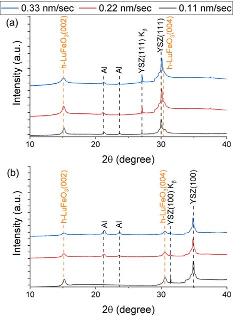
X-ray diffraction. Microphotographs of b-Fe2O3/ in the heterostructure on the YSZ(100) substrate
h-LuFeO3/YSZ heterostructure cross-sections (Fig.6c, d) can be explained by the fact that, in the
(Fig. 6 a, c) indicate a higher uniformity and less former case, the critical thickness of the b-Fe2O3
surface roughness of the h-LuFeO3 layer grown film is exceeded, above which the energy lowering
on YSZ(111) substrate compare to one deposited of b-Fe 2 O 3 (111)//h-LuFeO 3 (001) epitaxial
on YSZ(100). This observation can be explained contact turns out to be insufficient to stabilize
by the previously described in-plane variant this metastable modification of iron oxide. At
growth of h-LuFeO3 on YSZ(100), which results the same time, in the heterostructure on the
in the formation of a films with microstructure YSZ(100) substrate, b-Fe2O3 grows in a different
fragmented into nanoscale domains [25]. The orientation relative to h-LuFeO3, which obviously
402Condensed Matter and Interphases / Конденсированные среды и межфазные границы 2021;23(2): 396–405
A. R. Kaul et al. TSF-MOCVD – a novel technique for chemical vapour deposition...
Fig. 6. Results of cross-section TEM of heterostructures (a, b) b-Fe2O3 (111)//h-LuFeO3 (001)//YSZ (111) and
(c, d) b-Fe2O3 (001)//h-LuFeO3 (001)//YSZ (100)
leads to an increase in the critical thickness of occurs at a low total pressure in the reactor, the
this epitaxially stabilized layer. This interesting precursor solution is available to the operator
aspect, the dependence of the critical thickness throughout the experiment, which allows one
on the orientetion of epitaxially stabilized phase, to change the composition of the solution and/
will be clarified by further calculations of the or its concentration, make a cyclic change,
interface energies using the algorithm described and to add new components to it. The new
by us in [25]. method was used for the deposition of СеО2
films, the possibility of a smooth change in the
4. Conclusions deposition rate, its effect, as well as the effect of
Thus, we have implemented a new version heterovalent doping on the texture of the films
of the MOCVD with an original method for are shown. The great preparative capabilities of
supplying volatile precursors to the reactor, the proposed method for the growth of epitaxial
called TSD-MOCVD, which combines the heterostructures with a clear interface were
advantages of liquid-phase and solid-state based on the examples of b-Fe 2O 3(111)//h-
single-source MOCVD variants. The deposition LuFeO 3(001)//YSZ(111) and b-Fe 2O 3(001)//h-
403Condensed Matter and Interphases / Конденсированные среды и межфазные границы 2021;23(2): 396–405
A. R. Kaul et al. TSF-MOCVD – a novel technique for chemical vapour deposition...
LuFeO3(001)//YSZ(100). The possibility of the 7. Choy K. L. Chemical vapour deposition of
epitaxy of metastable b-Fe2O3 polymorph on coatings. Progress in Materials Science. 2003;48(2):
the surface of hexagonal lutetium ferrite was 5 7– 1 7 0 . h t t p s : / / d o i . o r g / 1 0 . 1 0 1 6 / s 0 0 7 9 -
revealed for the first time The existence of both 6425(01)00009-3
8. Dubourdieu C., Rosina M., Audier M., Weiss F.,
phases is explained within the framework of the
Sénateur J. P., Dooryhee E., Hodeau J. L. Application
phenomenon of epitaxial stabilization. Such of pulsed liquid-injection MOCVD to the growth of
film composites will be further investigated for ultrathin epitaxial oxides for magnetic heterostructures.
possible multiferroic properties. Thin Solid Films. 2001;400(1–2): 81–84. https://doi.
org/10.1016/s0040-6090(01)01457-2
Author contributions 9. Samoilenkov S .V., Stefan M. A., Wahl G. MOCVD
Kaul A. R. – scientific leadership, research of thick YSZ coatings using acetylacetonates. Surface
concept, text writing. Nigaard R. R. and Ratov and Coatings Technology. 2005;192(1): 117–123.
skiy V. Yu. – conducting experiments on gas-phase https://doi.org/10.1016/j.surfcoat.2004.03.019
10. Weiss F., Audier M., Bartasyte A., Bellet D.,
deposition of thin films and heterostructures,
Girardot C., Jimenez C., … Ternon C. Multifunctional
processing the results of X-ray diffraction and oxide nanostructures by metal-organic chemical vapor
transmission electron microscopy, text writing. deposition (MOCVD). Pure and Applied Chemistry.
Vasiliev A. L. – carrying out transmission electron 2009;81(8): 1523–1534. https://doi.org/10.1351/pac-
microscopy and discussion of its results. con-08-08-10
11. Sénateur J.-P., Dubourdieu C., Galindo V.,
Conflict of interests Weiss F., Abrutis A. Application of pulsed injection
The authors declare that they have no MOCVD to the deposition of oxide single layers and
known competing financial interests or personal superlattices. In: Innovative processing of films and
relationships that could have influenced the work nanocrystalline powders. 2002. p. 71–105 https://doi.
org/10.1142/9781860949623_0003.
reported in this paper.
12. Kartavtseva M. S., Gorbenko O. Y., Kaul A. R.,
References Akbashev A. R., Murzina T. V., Fusil S., Barthélémy A.,
Pailloux F. BiFeO3 thin films prepared by MOCVD.
1. Blocher J. Coating by сhemical vapor deposition
Surface and Coatings Technology. 2007;201(22-23):
(CVD). SAE Technical Paper Series. 1973;82: 1780–6.
9149–9153. https://doi.org/10.1016/j.
https://doi.org/10.4271/730543
surfcoat.2007.04.099
2. Pierson H. Handbook of chemical vapor deposition.
13. Bibes M., Gorbenko O., Martínez B., Kaul A.,
2nd ed. Noyes Publications; 1999. 506 p. https://doi.
Fontcuberta J. Alkaline-doped manganese perovskite
org/10.1016/B978-081551432-9.50005-X
thin films grown by MOCVD. Journal of Magnetism and
3. Syrkin V. G. CVD- metod. Khimicheskaya
Magnetic Materials. 2000;211(1-3): 47–53. https://doi.
parofaznaya matellizatsiya [CVD-method of chemical
org/10.1016/s0304-8853(99)00712-x
vapor-phase metallization]. Nauka Publ.; 2000. 495 p.
14. Decker W., Erokhin Y., Gorbenko O., Graboy I.,
(In Russ.)
Kaul A., Nurnberg A., Pulver M., Stolle R., Wahl G..
4. Akchurin R. H., Marmalyuk А. А. MOS-gidridnaya
Low-pressure single aerosol source MOCVD of YBCO
epitaksiya v tekhnologii materialov fotoniki i elektroniki
thin films. Journal of Alloys and Compounds.
[МОС-hydrid epitaxy in the technology of materials
1993;195(C): 291–294. https://doi.org/10.1016/0925-
for photonics and electronics]. Technosphera Publ.;
8388(93)90742-6
2018. 488 p. (In Russ.)
15. Kaul A. R., Seleznev B. V. New principle of
5. Wright P. J., Crosbie M. J., Lane P. A., Williams D. J.,
feeding for flash evaporation MOCVD devices. Le
Jones A. C., Leedham T. J., Davies H. O. Metal organic
Journal de Physique IV. 1993;3(3): 375–378. https://
chemical vapor deposition (MOCVD) of oxides and
doi.org/10.1051/jp4:1993351
ferroelectric materials. Journal of Materials Science:
16. Menushenkov A. P., Ivanov V. G., Chepikov V.
Materials in Electronics. 2002;13(11): 671–678. https://
N., Nygaard R., Soldatenko A., Rudnev I. A., …
doi.org/10.1023/a:1020618411750
Monteseguro V. Correlation of local structure
6. Wahl G., Arndt J., Stadel O. Chemical vapor
peculiarities and critical current density of 2G MOCVD
deposition of superconductor and oxide films. In:
Y B CO t a p e s w i t h B a Z r O 3 n a n o i n c l u s i o n s .
Chemical physics of thin film deposition processes for
Superconductor Science and Technology. 2017;30(4):
micro- and nano-technologies. Springer; 2002. p.
045003. https://doi.org/10.1088/1361-6668/aa599c
145–170. https://doi.org/10.1007/978-94-010-0353-
17. Shukin A. Е., Kaul. A. R., Vasiliev A. L.,
7_7
Rudnev I. A. Synthesis, structure and superconducting
404Condensed Matter and Interphases / Конденсированные среды и межфазные границы 2021;23(2): 396–405
A. R. Kaul et al. TSF-MOCVD – a novel technique for chemical vapour deposition...
properties of laminated thin film composites Multiferroic h-LuFeO3 thin films on (111) and (100)
YBа2Cu3O7–δ/Y2O3 as the components of 2G HTS tapes. surfaces of YSZ substrates: An experimental and
Kondensirovannye sredy i mezhfaznye granitsy = theoretical study. ACS Applied Electronic Materials.
Condensed Matter and Interphases. 2021;23(1): 122– 2021;3(2): 1015–1022. https://doi.org/10.1021/
139. https://doi.org/10.17308/kcmf.2021.23/3313 acsaelm.0c01127
18. Kaul A. R., Seleznev B. V., Sharovarov D. I., 26. Zboril R., Mashlan M., Krausova D., Pikal P.
Nygaard R. R., Osipova Yu. A., Makarevich А. М., Cubic b-Fe 2 O 3 as the product of the thermal
Sadykov I. I. Feeding system for supplying volatile decomposition of Fe 2(SO 4) 3. Hyperfine Interact.
compounds in reactors of chemical vapor-phase 1 9 9 9 ; 1 2 0 – 1 2 1 ( 1 – 8 ) : 4 9 7– 5 0 1 . h t t p s : / / d o i .
deposition: Patent No 2722914 RF. Claim. 03.12.2019. org/10.1023/a:1017018111071
Publ. 04.06.2020. Byul. No 2019139340. 27. Manimuthu P., Manikandan M., Selvi M. M.,
19. Niu G., Zoellner M. H., Schroeder T., Schaefer Venkateswaran C. Multiferroic Lu3Fe5O12 for magneto-
A., Jhang J. H., Zielasek V., … Reichling M. Controlling dielectric applications. AIP Conference Proceedings.
the physics and chemistry of binary and ternary 2012;1447(1): 1205–1206. https://doi.
praseodymium and cerium oxide systems. Physical org/10.1063/1.4710443
Chemistry Chemical Physics. 2015;17(38): 24513–2540.
https://doi.org/10.1039/c5cp02283e Information about the authors
20. Kummerle E. A., Heger G. The structures of Andrey R. Kaul, DSc in Chemistry, Full Professor at
C-Ce2O3+d, Ce7O12, and Ce11O20. Journal of Solid State the Chair of Inorganic Chemistry, Lomonosov Moscow
Chemistry. 1999;147(2): 485–500. https://doi. State University, Moscow, Russian Federation;
org/10.1006/jssc.1999.8403 arkaul@mail.ru. ORCID iD: https://orcid.org/0000-
21. Hayes W., Stoneham A. M. Defects and defect 0002-3582-3467.
processes in nonmetallic solids. New York: John Roy R. Nygaard, Junior Research Fellow at the Chair
Wiley & Sons; 2004. 472 p. of Inorganic Chemistry, Lomonosov Moscow State
22. Chowdhury U., Goswami S., Bhattacharya D., University, Moscow, Russian Federation; e-mail:
Rajput S. S., Mall A. K., Garg A., … Bhattacharya D. rnygaard@mail.ru. ORCID iD:
Origin of ferroelectricity in orthorhombic LuFeO3.
Vadim Yu. Ratovskiy, student at the Higher School
Physical Review B. 2017;100(19): 1–5. https://doi.
of Material Science, Lomonosov Moscow State
org/10.1103/physrevb.100.195116
University, Moscow, Russian Federation; e-mail:
23. Bossak A., Graboy I., Gorbenko O., Kaul A.,
vratovskiy@bk.ru. ORCID iD: https://orcid.org/0000-
Kartavtseva M., Svetchnikov V., Zandbergen H. W. XRD
0003-1657-110X.
and HREM studies of epitaxially stabilized hexagonal
orthoferrites RFeO3 (R = Eu-Lu). Chemistry of Materials. Alexander L. Vasiliev, PhD in Physics and
2004;16(9): 1751–1755. https://doi.org/10.1021/ Mathematics, Associate Professor at the Faculty of
cm0353660 NBICS, Moscow Institute of Physics and Technology,
24. Kaul A. R., Gorbenko O. Yu., Kamenev A. A. Moscow, Russian Federation; email: a.vasiliev56@
The role of heteroepitaxy in the development of new gmail.com. ORCID iD: https://orcid.org/0000-0001-
thin-film oxide-based functional materials. Russian 7884-4180.
Chemical Reviews. 2004;73(9): 861–880. https://doi. Received 1 July 2021; Approved after reviewing
org/10.1070/rc2004v073n09abeh000919 15 July 2021; Accepted for publication 15 August 2021;
25. Markelova M, Nygaard R, Tsymbarenko D, Published online 25 September 2021.
Shurkina A, Abramov A, Amelichev V, … Kaul A. Translated by Valentina Mittova
Edited and proofread by Simon Cox
405You can also read