Transportation container for pre processing cytogenetic assays in radiation accidents - Nature
←
→
Page content transcription
If your browser does not render page correctly, please read the page content below
www.nature.com/scientificreports
OPEN Transportation container
for pre‑processing cytogenetic
assays in radiation accidents
Jian Gu1*, Brett Duane1, Mikhail Repin2, David J. Brenner2 & Frederic Zenhausern1*
We report a shipping container that enables a disruptive logistics for cytogenetic biodosimetry for
radiation countermeasures through pre-processing cell culture during transportation. The container
showed precise temperature control (< 0.01 °C) with uniform sample temperature (< 0.1 °C) to meet
the biodosimetry assay requirements. Using an existing insulated shipping box and long shelf life
alkaline batteries makes it ideal for national stockpile. Dose curve of cytogenetic biodosimetry assay
using the shipping container showed clear dose response and high linear correlation with the control
dose curve using a laboratory incubator (Pearson’s correlation coefficient: 0.992). The container’s
ability of pre-processing biological samples during transportation could have a significant impact on
radiation countermeasure, as well as potential impacts in other applications such as biobanking, novel
molecular or cell-based assays or therapies.
Exposure to ionizing radiation continues to be a threat to public safety should a nuclear/radiological event hap-
pen, such as an improvised nuclear device (IND) or a radiation dispersal device (RDD) detonated by a terrorist,
or a nuclear power plant disaster caused by nature or human e rror1,2. The dangerous exposure zone can cover a
large area due to different spreading routes of the radioactive contaminants, which can cause a large population
to worry about their exposure level. In this scenario, a rapid triage tool is critical to give patients needed treat-
ment as well as to ease the anxiety of the “healthy worries”3.
Triage after a nuclear/radiological event can be multiple stages by different dosimetry a ssays3. After an ini-
tial point-of-care (POC) triage, a high-throughput dosimetry system is expected to give more accurate dose
estimates. Sullivan et al. assessed different biodosimetry methods for radiation countermeasure, including lym-
phocyte depletion kinetics (LDK) assay, γ-H2AX assay, dicentric chromosome assay (DCA), cytokinesis-block
micronucleus (CBMN) assay e tc3. These assays differ by their complexity, applicable ranges of time after the
radiological event and dose. For example, the LDK assay can be performed in a POC setting, and a rough dose
estimate could be obtained by a single cell count. The γ-H2AX assay has a dose range of 0.5–5 Gy and time
range of 24–48 h, which could be suitable for a quick initial triage, but its short time window could also limit its
usability. Cytogenetic assays, such as DCA and CBMN, are more established assays, and DCA is considered the
“gold standard” for biodosimetry.
Among the different biodosimetry assays, CBMN is one of the cytogenetic biodosimetry assays recommended
by the International Atomic Energy Agency (IAEA) for radiation exposure by examining micronucleus formation
from human peripheral blood lymphocytes4. It is promising for large population triage application because it is
an established assay that could be deployed quickly, and it is more suitable for automation comparing with other
established cytogenetic biodosimetry assays (such as DCA). Recently, automation of the CBMN assay has been
demonstrated for high-throughput processing of large number of samples using commercial robotic s ystems5,6.
To streamline the dosimetry process in the aftermath of a nuclear/radiological event, a fingerstick blood self-
collector was also developed to address the sample collection b ottleneck7. Despite these efforts, however, chal-
lenges remain to apply CBMN for population triage after a large scale nuclear/radiological event.
The main challenge of CBMN for radiation triage is its long response time due to sample transportation and
a required cell culture step at beginning of the assay. Figure 1A shows the current logistics of CBMN assay for
radiation triage. Due to the complexity of the CBMN assay, samples must be shipped to a central laboratory
for processing after collection. With limited cytogenetic laboratories within the USA and around the world, air
transportation is expected. The shipping time can last 3 days or longer depending on weather conditions, possible
1
Center for Applied NanoBioscience and Medicine, Department of Basic Medical Sciences, The University of
Arizona, College of Medicine, Phoenix, AZ 85004, USA. 2Center for Radiological Research, Columbia University,
Vagelos College of Physicians and Surgeons, New York, NY 10032, USA. *email: jgu10@arizona.edu; fzenhaus@
arizona.edu
Scientific Reports | (2021) 11:10398 | https://doi.org/10.1038/s41598-021-89832-x 1
Vol.:(0123456789)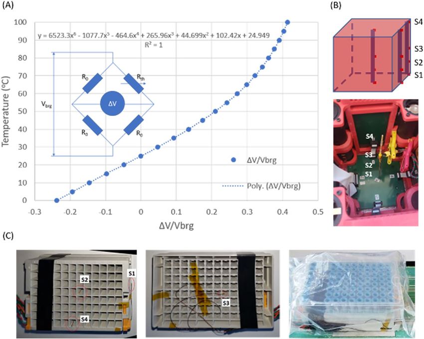
www.nature.com/scientificreports/
Figure 1. (A) Existing cytogenetic biodosimetry logistics: the response time to get the 1st dose result can be
as long as 6 days due to shipping and cell culture; (B) our novel cytogenetic biodosimetry logistics: cell culture
during transportation can dramatically decrease the response time of the biodosimetry to 3 days.
aircraft mechanical issues and delays at customs. Once samples are received, blood cells need to be cultured
for ~ 72 h before they can be harvested and micronuclei are identified. Even though the cell culture time can be
shortened to 54 h using an accelerated CBMN a ssay8, the overall response time (i.e., the time for the first dose
estimate to be available after sample collection) can still be 6 days or longer. To address this long response time,
we propose a novel logistics for the CBMN assay, i.e., to use a shipping incubator to perform the cell culture
immediately after the sample collection and during transportation (Fig. 1B). In this way, the assay response time
can be dramatically reduced to ~ 3 days, half of the current response time.
There are multiple requirements for a shipping container to perform cell culture for CBMN assay for radiation
countermeasure. First, to ensure accurate cytogenetic endpoints are detected, the temperature of the cell culture
needs to be controlled within 0.5 °C of 37 °C4,9. Second, the battery needs to last for the entire culture duration
(54–72 h) even in cold winter weather. Third, it needs to be low cost and easy to store in the national stockpile.
There are previous reports on temperature-controlled shipment of biological s amples10,11, but the temperature
usually spans a range of several degrees Celsius, too wide for CBMN assay. There are also commercial shipping
incubators (e.g., iQ from MicroQ Technologies, Scottsdale, AZ, or BioTherm from CryoLogic, Australia) that can
control the shipping temperature within 0.5 °C of 37 °C, but they are usually bulky, high cost with rechargeable
batteries (that requires charging before use and may fail in storage) and not suitable for national stockpile. In this
paper, we report our efforts to build a shipping container for CBMN cell culture. We call it micro-Cytogenetic
Rapid Assay Integrated Transporter (µCRAIT) box. The name also contains all the key elements of the container,
i.e., micro-Controlled Resistive heating of long shelf life Alkaline-battery-powered traditional Insulating shipping
box for precise Temperature control. The box design, temperature control, battery life, resistance to mechanical
shock, and initial application to CBMN assay with cell culture during transportation will be reported.
Experimental results
µCRAIT box design and prototyping. The main concept of the µCRAIT box starts with the idea that
the internal box temperature can be controlled by making the six box internal surfaces an isothermal surface,
which will make the box temperature the same as the isothermal surface temperature. To control the six internal
surfaces at the desired 37 °C, a printed circuit board (PCB) is used for each surface as an individual temperature-
controlled surface (Fig. 2A). The PCB not only supports the temperature control circuits, but also serves as a
good heat conductor for uniform temperature across the board due to internal copper layers. The temperature of
each PCB is measured by a thermistor mounted on the board. Six resistors distributed across the board are used
to maintain the board temperature at 37 °C by resistive heating (Fig. 2A). A 3D printed frame is used to mechani-
cally hold the six PCBs together (Fig. 2B). It also holds four battery holders at the corners. Then the system can
be loaded into a traditional insulating shipping box to generate the 37 °C environment for cell culture during
transportation (Fig. 2C). Two commercial vacuum-insulated-panel (VIP) shipping boxes were used in our study
due to the low thermal conductivity of the VIP material, a dual-wall box and a single-wall box. The top of the
frame with the PCB can be flipped open with a printed hinge for sample loading.
To control the temperature, a microcontroller system is designed and implemented using the PCBs. The
system is powered by 8 D-cell alkaline batteries for heating and operation (two for each battery holder). Alkaline
Scientific Reports | (2021) 11:10398 | https://doi.org/10.1038/s41598-021-89832-x 2
Vol:.(1234567890)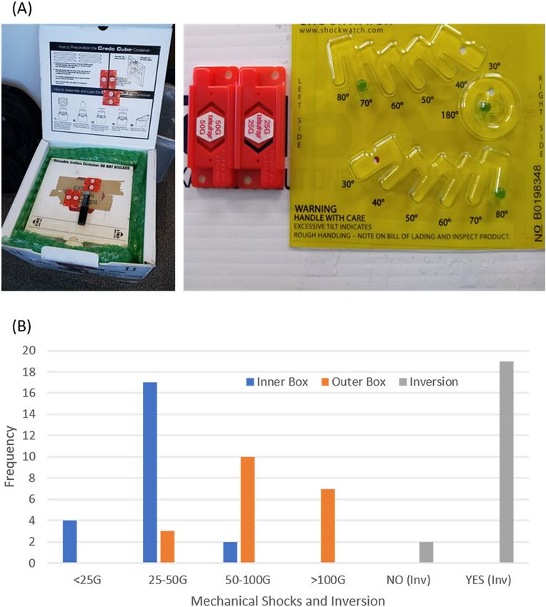
www.nature.com/scientificreports/
Figure 2. (A) Six PCBs connected by ribbon cables that are used to form the temperature-controlled isothermal
internal surfaces of a µCRAIT box. Each PCB temperature is controlled by resistive heating of six resistors and
microcontroller feedback of a thermistor; (B) a 3D-printed frame that holds the six PCBs, as well as 4 battery
holders at the corners; (C) a µCRAIT box by housing the 3D-printed PCB frame box inside a traditional dual-
wall VIP insulated shipping box; (D) typical temperature curves of the six PCB panels heated towards 37 °C
from room temperature.
battery is chosen due to its low cost and long shelf life (5–10 years), which is ideal for national stockpile. A coin
cell (CR2032), which also has long shelf life (10–12 years), is used as a backup power for general operation
(excluding heating) in case the event a transient impact causes the D cells to be momentarily disconnected. The
system uses a proportional-integral-derivative (PID) feedback loop to accurately control the PCB temperature,
and pulse-width-modulation (PWM) for heater power control. The PCB temperature is measured by resistance
change of the thermistor in a Wheatstone bridge. The microcontroller also has the functions of real time clock
(RTC), communication with external computer, and memory for data logging. The logged parameters include
date and time, PCB temperatures, battery voltage, heating power and other significant events such as power
disruption, disabling of heating etc. For our µCRAIT box using the dual-wall VIP shipping box, it usually takes
about 2 h for the box to heat up from room temperature to 37 °C. Figure 2D shows a typical set of temperature
curves of all six PCB panels heated toward 37 °C. The PID and PWM circuits accurately controlled the tempera-
ture at the setpoint within 0.01 °C.
Temperature measurement, calibration and characterization. Precise temperature control
(37 ± 0.5 °C) is a main goal of the µCRAIT box. For accurate temperature measurement, a thermistor in a
Wheatstone bridge (Fig. 3A) mounted on each PCB was used to measure the temperature of each board. A ther-
mistor was chosen for its sensitivity, stability and ease for integration12,13. The Wheatstone bridge was chosen for
its insensitivity to voltage variation. The temperature-dependent resistance of a thermistor can be described by
the Steinhart–Hart e quation14. However, it is more convenient for the microcontroller to compute temperature
T directly from the unbalance of the bridge, i.e., the ratio between output and input voltages of the bridge ∆V/
Vbrg. The unbalance of the bridge can be mathematically deduced as:
Scientific Reports | (2021) 11:10398 | https://doi.org/10.1038/s41598-021-89832-x 3
Vol.:(0123456789)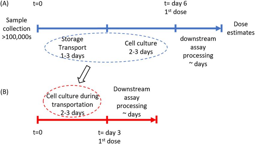
www.nature.com/scientificreports/
Figure 3. (A) Schematics of the Wheatstone bridge circuit; the T versus ∆V/Vbrg curve calculated using
Eq. (1) and manufacturer’s thermistor resistance data was fitted by a sextic polynomial function with a R-Square
value of 1; (B) schematics of the four wired thermistors on a stick to characterize the internal temperature
of the µCRAIT box at the corner, side and center of the box; an image of the stick sensors measuring center
temperature of the box is shown; (C) images showing the wired sensors to measure temperatures of the sample
rack at different locations.
�V 1 R0 − Rth (T)
Vbrg
= ∗
2 R0 + Rth (T) (1)
where R0 is the known resistance of the bridge resistors, Rth is the variable resistance of the thermistor. Using
manufacturer’s Rth(T) data, T versus ∆V/Vbrg was plotted for the temperature range between 0 and 100 °C and
2 (Goodness-of-Fit) value of 1 (Fig. 3A). The polynomial was then
fitted by a sextic polynomial function with a R
used by the microcontroller’s firmware to measure the PCB temperature.
For accurate temperature measurement, each temperature sensing circuit was calibrated using a Resistance
Temperature Detector (RTD) reference thermometer. To do this, the µCRAIT box and the reference thermometer
were put inside a laboratory incubator with a fan to reach uniform temperature inside the incubator. The PCB
temperatures were read out at both 37 °C and 32 °C and compared with those from the reference thermometer.
Because we are mainly concerned about the accuracy of the temperature at 37 °C, an offset was first used for each
PCB to correct the temperature at 37 °C. The corrected temperature T cor can be expressed as:
Tcor = Traw + Offset, Offset = Tref ,37 − Traw,37 so that Tcor,37 = Tref ,37 (2)
where Traw is the raw PBC temperature measured by the unbalance of the Wheatstone bridge and the thermistor
sextic polynomial curve, and T ref,37, Traw,37, Tcor,37 are the reference, PBC, and offset-corrected temperature read-
ings at the 37 °C calibration.
To further correct the temperature around 37 °C, because the T versus ∆V/Vbrg curve around and below 37 °C
is quite linear (Fig. 3A), a sloped linear correction was used for each PCB to make the board temperature the
same as the RTD reading at 32 °C while keeping the 37 °C calibration intact. The further corrected temperature
Tcor′ for each PCB can be expressed as:
Scientific Reports | (2021) 11:10398 | https://doi.org/10.1038/s41598-021-89832-x 4
Vol:.(1234567890)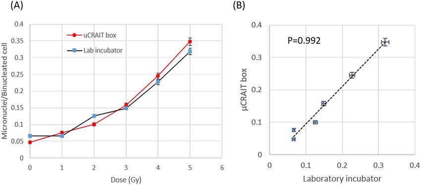
www.nature.com/scientificreports/
Sensor # Offset (°C) STDoffset (°C) Slope STDSlope
µCRAIT PCBs
0 0.527 0.022 0.0084 0.0028
1 0.407 0.037 0.0067 0.0055
2 1.145 0.031 0.0106 0.0040
3 0.785 0.015 0.0089 0.0018
4 1.057 0.023 0.0088 0.0029
5 1.026 0.023 0.0087 0.0040
Wired sensors
1 − 0.052 0.021 − 0.0287 0.0031
2 − 0.062 0.049 − 0.0327 0.0057
3 0.032 0.031 − 0.0304 0.0037
4 0.152 0.056 − 0.0234 0.0104
Table 1. Temperature characterization of the µCRAIT box and the wired thermistor sensors.
Sensor# 1 2 3 4 Average STD
µCRAIT box
Corner 36.54 36.75 36.96 37.11 36.84 0.250
Side 36.57 36.69 36.78 36.85 36.72 0.120
Center 36.65 36.61 36.64 36.73 36.66 0.052
Dummy sample rack payload 36.71 36.64 36.65 36.73 36.68 0.046
Table 2. µCRAIT box and sample rack temperature uniformity characterization. For µCRAIT box, the sensors
1–4 were located at bottom, mid-bottom, middle and top of the stick. For the dummy sample rack, the sensors
1–4 were located at outside short edge, inside center, outside bottom and inside long edge of the rack.
′ Tref ,32 − Tcor,32 ′
(3)
Tcor = Tcor + Slope ∗ Tcor − Tcor,37 , Slope = so that Tcor,32 = Tref ,32
Tcor,32 − Tcor,37
where Tcor,32 and T
ref,32 are the offset-corrected PBC temperature and reference temperature readings at the 32 °C
calibration.
We conducted six calibration experiments to collect information on the uncertainty of the temperature meas-
urement. Table 1 lists the averages and standard deviations (STDs) of the Offsets and Slopes for all six PCBs from
the six calibrations. We can see that the Offsets have average values of 0.407 to 1.145 °C with S TDOffset 0.015 to
0.037 °C. The Slopes vary between 0.0067 and 0.0106 with STDSlope between 0.0018 and 0.0055. Because the box
can control the temperature 0.01 °C or less away from the 37 °C setpoint, the Slope correction is not significant
for the box temperature control at the setpoint. The low S TDOffset shows that the PBC can be quite accurately
controlled at 37 °C with an error much smaller than our targeted 0.5 °C.
With the PCB temperature calibrated and heated to 37 °C, the internal temperature of the µCRAIT box was
characterized by four wired thermistor sensors mounted to a stick with a length similar to the internal dimen-
sion of the box (Fig. 3B, sensors 1–4 were located at 0, 25, 50 and 100% positions of the stick from bottom to
top). The wired thermistor temperature sensing circuits were constructed and calibrated similar to those for the
PCB temperature sensing and calibration. The Offsets, Slopes, their STDs are also listed in Table 1. Because the
sensors will measure temperatures very close to 37 °C (within 0.5 °C or less), the total STD can be estimated by
STDOffset + ∆T*STDSlope with maximum values of 0.023–0.061 °C (∆T = 0.5 °C). The small STDs allow the sensors
to characterize the box temperature within the targeted range (37 ± 0.5 °C).
With the sensors on the stick calibrated, the temperatures at corner, side and box center inside the µCRAIT
box were measured when the box was heated to 37 °C (Fig. 3B). The box internal temperatures at the equilibrium
are listed in Table 2. The values are calculated using Eq. (3) with a T cor,37 value of 36.93 °C. We can see that the
spreading of the temperature for the whole box is less than 0.6 °C. It is more uniform in the center of the box
(temperature spread < 0.12 °C) where the sample will be located. The corner and side of the box have slightly
higher temperatures than the center because they are closer to the heat source. The top of the box (sensor 4) is
also slightly warmer than the bottom (sensor 1) because warmer air has a lower density and tends to rise.
For CBMN assay, samples will be transported in 96-tube-rack format 2D-barcoded storage tubes. To further
understand the temperature experienced by the samples, the wired sensors were used to measure the tempera-
tures at different locations of a tube rack (Fig. 3C), loaded with dummy sample tubes and placed inside the
center of the µCRAIT box. The steady state temperatures at different locations (S1: outer short side; S2: center;
S3: bottom; S4: inner long side) are quite uniform across the sample rack with a temperature spread of 0.09 °C
(Table 2). The average temperature is, however, 0.32 °C lower than 37 °C. We attribute this to the fact that our
Scientific Reports | (2021) 11:10398 | https://doi.org/10.1038/s41598-021-89832-x 5
Vol.:(0123456789)www.nature.com/scientificreports/
Insulating box info
Internal dimensions
Total insulation # of D-cell alkaline
Box name Insulation material thickness d (in) L (in) W (in) H (in) batteries Duration t (h)
Styrofoam box Polystyrene foam 1.8 7.8 6.8 6.5 4 9.5
Credo single-wall VIP 1.8 7.8 6.8 6 4 57.5
Credo dual-wall VIP 2 7.8 7.8 7.8 8 114
Table 3. Duration of µCRAIT box working at fridge temperature (4 °C) for three box configurations.
current PCB panels do not form a completely enclosed isothermal space, and heat can be lost through the space
between the PCBs. To compensate this temperature drop, we raised the temperature setpoints of all PCBs to
37.3 °C for an average sample temperature of 36.98 °C for our CMBN assay blood culture during transporta-
tion. The overall uncertainty of the sample temperature can be estimated by the sum of maximum STDs from
the PBCs (0.037 °C) and the wired sensors (0.061 °C), which shows a value of 0.098 °C. This low value puts the
sample temperature well within the targeted 37 ± 0.5 °C range. We expect very low measurement variations at
32 °C and 37 °C from the RTD reference thermometer, which are neglected in our estimation. According to the
manufacture specification, the RTD thermometer has an accuracy of ± 0.03 °C over the range of − 30 to 150 °C,
which is low and will not affect our temperature measurement significantly.
Battery selection and capacity. The battery is another key aspect of the µCRAIT box. The ideal battery
should be low cost with long shelf life for national stockpile. It should also have enough capacity to power the
box at 37 °C for several days during transportation, even in a cold winter.
Alkaline battery fits the national stockpile requirement very well due to its low cost and long shelf life
(5–10 years), so it was selected as the main battery source for the system control and box heating. The common
coin cell battery also has long shelf life (10–12 years) and was used as the backup power for the microcontroller
operation excluding heating.
To maintain 37 °C during transportation, any heat loss due to lower ambient temperature needs to be com-
pensated by the resistive heating of the PCBs. µCRAIT boxes use traditional insulating shipping boxes to reduce
heat loss and extend the culture temperature duration. If we assume the heat loss is mainly due to thermal
conductivity of the box’s insulation layer, we can use Fick’s Law to approximate the heat loss (dQ/dt) of the box
with a simple 1D model:
dQ κ ∗A κ ∗A
= −C ∗ ∗ �T = −C ∗ ∗ (37 − TAmb ) (4)
dt d d
where κ and d are the thermal conductivity and thickness of the box insulation respectively, A is the total box
internal surface area, TAmb is the ambient temperature in Celsius, and C is a constant depending on the box
geometry (for cubic shaped boxes, the constants are similar). The duration (t) for the battery pack to maintain
the culture temperature would be:
Ebat
t=
(5)
dQ
− dt
where Ebat is the energy of the battery pack.
To estimate the insulation and size of the battery pack, we tested three box insulation/battery configurations
at refrigerator temperature (4 °C), as shown in Table 3. We can see that a commonly used Styrofoam box with
4 D-cell batteries can keep the µCRAIT box at the target 37 °C for 9.5 h. However, a single-wall VIP insulated
box with 4 D-cell batteries can last 57.5 h, and a dual-wall VIP box with similar insulation thickness but dou-
bled D-cell batteries can double the working time to 114 h (almost 5 days), more than sufficient for the 3 days
required by the CBMN sample transportation. Considering the facts that all the box dimensions and insulation
thicknesses are similar and the thermal conductivity of Styrofoam is about 4–13 times that of VIP (~ 0.030–0.040
vs. ~ 0.003–0.007 Wm−1 K−1)15,16, the results are consistent with Eqs. (4, 5).
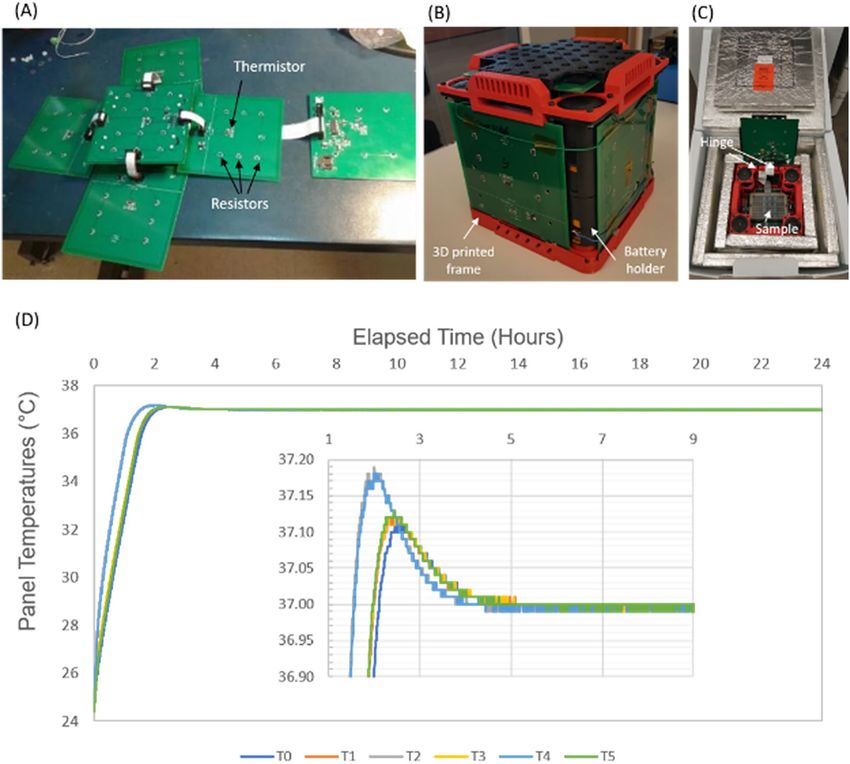
Mechanical monitoring during transportation. Mechanical shock is another concern for the µCRAIT
box. Mechanical shock during transportation is a threat to electronic products in general17, but it is more signifi-
cant for transporting actively working electronics, such as the µCRAIT box, because damage to the electronics
during transportation could ruin all the samples. To monitor the mechanical shock and handling of the box
during transportation, we used Teladrop Drop-N-Tell Resettable Shock Indicators to show the G-ranges of the
maximum shock (Fig. 4A). The tilt and inversion of the box were monitored by TiltWatch Plus. Over 20 ship-
ments have been conducted between Phoenix, AZ and New York, NY using FedEx Express services (FedEx
Corporation, Memphis, TN).
Our initial shipment tests used the commercial VIP Credo box with just a plastic outer. However, we observed
damage to the plastic outer as well as the VIP panels over repeated shipments. To avoid box damage and reduce
mechanical shock experienced by the µCRAIT box, we housed the µCRAIT box inside another outer box cush-
ioned by bubble wraps (Fig. 4A). 50G and 100G Shock Indicators were attached to the outer box, and 25G and
Scientific Reports | (2021) 11:10398 | https://doi.org/10.1038/s41598-021-89832-x 6
Vol:.(1234567890)www.nature.com/scientificreports/
Figure 4. (A) Images of a µCRAIT box (with an outer box) and the Drop-N-Tell Shock Indicators and
TiltWatch Plus used to monitor the mechanical shock and tilt of the box experienced during transportation; (B)
mechanical shock G-range and inversion frequency from over twenty shipments between Phoenix, AZ and New
York, NY by FedEx Express services.
50G Indicators were attached to the inner box. The G-ranges and frequency experienced by the boxes are shown
in Fig. 4B. We can see that the outer box can experience > 100G shocks, and the inner box had shocks mostly in
25–50G range, but can also go above 50G. The TiltWatch Plus showed all boxes were tilted during shipments;
over 90% were also turned upside down (Fig. 4B). These results are consistent with FedEx’s policy that orienta-
tion of the package is not guaranteed during shipment.
Through the shipping experiments, we found that the PBCs and cable connections were not affected much
during transportation. The impact of the mechanical shocks was mainly on the battery holder. Our initial bat-
tery holder used metal clips to hold the battery, which can be permanently deformed during transportation to
disconnect the battery power. Switching to a battery holder with elastic spring as the battery contact solved this
issue. Momentary disconnects of the battery power were still observed during shipment according to our system
data log, but it did not affect the system performance due to transient nature of the event.
CBMN assay using µCRAIT box. To test the µCRAIT box for CBMN assay, non-irradiated and irradiated
human blood samples collected at Columbia University’s Center for Radiological Research (New York, NY) were
sent to The University of Arizona’s Center for Applied NanoBioscience and Medicine (Phoenix, AZ) by FedEx
Overnight inside the 37 °C µCRAIT box, and then shipped back to Columbia University immediately. The con-
trolled temperature condition of the box allowed incubation of cells for the CBMN assay to start immediately
following sample draw, gamma-irradiation of blood, as well as during transportation. A set of replicating control
samples was also cultured in a laboratory 5% CO2 incubator for comparison. As suggested by IAEA4, for cell
culture without 5% C O2, sample tubes should be fully capped, which was the case for our µCRAIT box samples.
This will also avoid any sample leakage during transportation. For the laboratory CO2 incubator, sample tubes
Scientific Reports | (2021) 11:10398 | https://doi.org/10.1038/s41598-021-89832-x 7
Vol.:(0123456789)www.nature.com/scientificreports/
Figure 5. (A) Dose curves of CBMN assays generated by cell cultures inside a µCRAIT box during
transportation and a laboratory CO2 incubator; both show clearly dose response; (B) dose responses from
µCRAIT box and the control laboratory incubator have a high linear correlation with a Pearson’s correlation
coefficient of 0.992; a linear trendline is also shown.
were loosely capped to allow gas exchange. We did observe a decrease of mitotic index without CO2 (see Sup-
plemental Figure S2). However, this decrease is not significant enough to prevent CBMN assay in our current
setting. The data of accelerated RABiT-II CBMN a ssay8 of the control blood samples and samples after 2-days
of shipping in µCRAIT box were obtained by processing all the samples in one 96-well plate at the same time.
The dose curves of micronuclei yield in binucleated cells in samples cultured in the µCRAIT box and cultured
in laboratory incubator are shown in Fig. 5A. Clear dose-dependent curves have been observed for both con-
ditions. A highly linear relationship exists between the two data sets with a Pearson’s correlation coefficient of
0.992 and a 95% confidence interval of (0.921, 0.999) (Fig. 5B). These data clearly demonstrate the feasibility of
µCRAIT box for cell culture during transportation for CBMN and possibly other cytogenetic biodosimetry assays.
Discussion and conclusion
A significant effort of this project is to ensure the cell culture temperature by the µCRAIT box is within 37 ± 0.5 °C.
This tight temperature requirement is suggested by IAEA for cytogenetic biodosiemtry assays, such as DCA and
CBMN assays4. The rationale behind it is that too low a temperature will result in a poor yield of metaphase or
binucleated cells. If the temperature is too high, cells will progress more rapidly through the cycle with unac-
ceptably high numbers of second-division metaphase or binucleated c ells9.
Low cost is also wanted for national stockpile. Commercial shipping incubators with metal construction and
rechargeable batteries can cost over $5,000 (iQ5 from MicroQ Technologies). By using alkaline batteries and
conventional shipping boxes, the cost for the current µCRAIT box is estimated to be < $400. A large portion
of the cost comes from the vacuum insulated Credo shipping box, which cost $310/box. The current µCRAIT
box is housing only one 96-tube rack. By scaling up the box size, more sample racks can be housed inside the
µCRAIT box and we expect the cost of the box per sample rack would drop accordingly because box volume
scales faster than the surface area. If the box cost drops to $100/rack, the cost for national stockpile for 1 million
people in a metropolitan area would cost ~ $1 million. At this time, a clear guidance is still needed from policy
makers regarding the cost, but we feel this cost is feasible within the total budget of local/Federal government
(e.g., ~ $12B for the State of Arizona in Fiscal Year 2021). Furthermore, a significant cost source of national
stockpile can come from warehouse storage. Our µCRAIT box has the potential to be folded during storage,
which can also lower the cost.
There are still areas that the µCRAIT box can be further developed. For example, a simple resistive heating
was used for the µCRAIT box because we expect the box ambient temperature to be < 37 °C during transporta-
tion in most cases. There are areas in the U.S. and around the world where the environmental temperature can
be > 37 °C during the summer. However, the box could still experience an ambient temperature of < 37 °C during
transportation if it is housed inside a temperature regulated vehicle or building. For the rare scenario of > 37 °C
ambient temperature, we are also developing a µCRAIT box with a passive phase change material layer to neu-
tralize the heat influx from outside to maintain the desired box temperature.
Another issue of our existing µCRAIT box is the time it takes to heat samples to the target temperature.
Currently heating an empty box from room temperature (~ 25 °C) to a steady state 37 °C takes ~ 2 h. Because
the internal space of the box is heated without active convection, it can take even longer (over 10 h) to warm a
sample rack from room temperature. To address this issue, we currently preheat the samples in a conventional
oven before we put them into a pre-warmed µCRAIT box for CBMN assay. To reduce the heating time, a fan can
be integrated in our future µCRAIT box to generate forced convection inside the box. Our preliminary results
Scientific Reports | (2021) 11:10398 | https://doi.org/10.1038/s41598-021-89832-x 8
Vol:.(1234567890)www.nature.com/scientificreports/
have shown that intermittent operation of a mini-fan can dramatically decrease the heating time with increased
temperature uniformity inside the box.
As we mentioned before, current PCBs do not touch at their edges to form an enclosed isothermal surface,
which can cause the internal box temperature lower than that of the boards. We envision our future µCRAIT
box would have a fully enclosed heat-conductive isothermal surface to address this issue. To demonstrate the
concept of the µCRAIT box, our current box was designed to house just one 96-tube rack. We are also in the
process of scaling up the box to host more sample racks.
In summary, we have demonstrated a novel transportation box (µCRAIT) for disruptive cytogenetic bio-
dosimetry logistics that uses traditional insulated shipping box, microcontrolled simple resistive heating, low
cost and long shelf life alkaline battery to achieve precise temperature control of the box’s internal space at
37 °C. The temperatures of the isothermal PCB surfaces can be controlled within 0.01 °C of the setpoint with
standard deviations of < 0.04 °C. After box calibration, the temperature is very uniform in the center of the box,
and a dummy 96-tube rack payload showed a steady state temperature variation of < 0.1 °C across the payload.
With 8 D-cell alkaline batteries, the box can maintain 37 °C at 4 °C ambient temperature for almost 5 days, long
enough for the cell culture of cytogenetic biodosimetry assays. The mechanical shock and tilt of the box during
transportation by a commercial shipping company (FedEx) were also characterized, and an appropriate battery
holder was selected to address the permanent battery disconnect issue. Finally, successful biodosiemtry CBMN
assay was demonstrated using blood samples cultured by the µCRAIT box during transportation with a clear
dose-dependent curve of micronuclei per binucleated cell ratio that has high linear-correlation with the labora-
tory control samples. Currently, civilian radiation countermeasure response in the U.S. is still planned at local
government level18. The U.S. Department of Defense (DOD) has established a biodosimetry network for military
personnel based on a group of biodosimetry methods, including LDK, traditional cytogenetic assays (DCA and
premature chromosome condensation (PCC)), and electron paramagnetic resonance (EPR)19. High throughput
biodosimetry methods such as the one reported in this manuscript are still highly needed. With the demonstrated
feasibility of sample pre-processing during transportation to dramatically reduce the response time, the µCRAIT
box could have significant impact on existing biodosimetry response for radiation countermeasures in several
aspects. The box is designed for any cellular biodosimetry assay which requires significant cell culturing time.
Thus, it can potentially be used for the two commonest cellular biodosimetry assays, specifically CBMN assay,
as described here, and the DCA a ssay20, both of which require significant cell culturing time. A third commonly
used cellular biodosimetry assay, γ-H2AX, does not generally require cell culturing; however, if the γ-H2AX assay
is being used as an assay for residual non-repaired DNA damage21, then the µCRAIT box would potentially be
useful. Finally, besides biodosimetry, the box also has potential impacts on other applications such as biobank-
ing, novel molecular or cell-based assays or therapies10,11,22.
Materials and methods
Ethics statement. All blood collections were approved by the institutional review boards of Columbia
University (IRB# AAAF2671) and done after written informed consents were given. All experiments were per-
formed in accordance with the relevant guidelines and regulations.
µCRAIT box design and prototyping. PCBs with 1.5-mm-thick Fire Retardant 4 (FR4) substrate and
two or four layers of 35-µm-thick copper were used to build the microcontroller. The PCB layout was designed
in house and fabricated by a local vendor (Advanced Circuits, Chandler, AZ). The schematics of the Wheatstone
bridge and heater circuits can be seen in Figure S1. The design left most copper on the board for good thermal
conduction. The system was also assembled in house. Ribbon cables were used to connect the PCBs together. The
frame holding the PCBs was printed by an uPrint SE Plus 3D printer (Stratasys, MN). The VIP insulating boxes
were purchased from Pelican BioThermal, LLC (Plymouth, MN).
Temperature calibration and characterization. The thermistors for PCB temperature sensing were
purchased from Vishay Americas, Inc (Part# NTHS1206N02N1002JE) with 10 kΩ at 25 °C. Three precision
resistors (10 kΩ, 0.1% tolerance TNPW120610K0BEEN by Vishay/Dale) were used as the known resistors in the
Wheatstone bridge. The sextic polynomial was fitted by Microsoft Excel. The RTD reference thermometer (SKU:
THS-222-555) was purchased from ThermoWorks (American Fork, UT). The laboratory incubator for tem-
perature calibration was a VWR 1545 General Purpose Incubator. The four wired thermistors were purchased
from TE Technology, Inc (MP-2444). They were mounted on the stick by heat shrink tubing and controlled by a
customer Wheatstone-bridge controller board for temperature measurement. The 96-tube rack format 2D-bar-
coded Matrix 1.0 ml sample storage tubes were purchased from ThermoFisher Scientific Inc (item# 3850). The
tube caps were the SepraSeal Caps from the same company (Item#4464).
Battery selection and capacity. D-cell alkaline batteries under different brand-names (Duracell, Ener-
gizer and Wincell) were purchased from local stores. Their capacities were characterized by their endurance
to power an electronic load under constant power (0.2 W), which has shown to be similar with a coefficient of
variation (CV) of 5%. The coin cell battery was the CR2032 battery. The Styrofoam box was one of the common
insulating boxes for shipping cold-chain reagents that we found in our lab. The single-wall and dual-wall VIP
Credo boxes were purchased from Pelican BioThermal, LLC (Plymouth, MN).
Mechanical monitoring during transportation. The 25G, 50G and 100G Teladrop Drop-N-Tell Reset-
table Shock Indicators were purchased from Telatemp Corp (Anaheim, CA). The TiltWatch Plus was purchased
Scientific Reports | (2021) 11:10398 | https://doi.org/10.1038/s41598-021-89832-x 9
Vol.:(0123456789)www.nature.com/scientificreports/
from Uline (Pleasant Prairie, WI). The metal-clip and the spring-loaded battery holders were both purchased
from Digi-Key Electronics (Part# 36-186-ND, and 708-1420-ND).
CBMN assay using µCRAIT box. Blood samples (2 ml) were collected into heparinized vacutainer tubes
(BD, Franklin Lakes, NJ) from 4 healthy volunteers at the Columbia Center for Radiological Research (New
York, NY). Blood samples were exposed to 0 (control), 1.0, 2.0, 3.0, 4.0 or 5.0 Gy of γ-rays at a dose rate of
0.70 Gy/min at Gammacell 40 137Cs irradiator (Atomic Energy of Canada Ltd., Mississauga, Canada). 60 μl of
human blood samples were pipetted into 1 ml 2D-barcoded Matrix storage tubes (Thermo Fisher Scientific Inc.,
Waltham, MA) and 500 μl of PB-MAX karyotyping media (Thermo Fisher Scientific) was added. Two identical
sets of Matrix tubes with irradiated and non-irradiated blood samples were put into two ANSI/SLAS microplate
format compatible 96-tube racks (24 tubes in each rack). One rack with samples was placed into the laboratory
incubator at 37 °C under 5% CO2 atmosphere with the tube tops loosely capped. The second sample rack was
prewarmed to 37 °C for 30 min inside an incubator with the tube tops fully capped by the SepraSeal caps, and
then loaded into prewarmed µCRAIT box for shipment. The box was shipped to The University of Arizona
(Phoenix, AZ), and then shipped back to Columbia University (New York, NY) the same day via FedEx Over-
night. On the second day after blood draw the µCRAIT box with blood samples was successfully delivered to
the Columbia Center for Radiological Research. After 44 h of cell incubation, cytochalasin-B (Sigma-Aldrich,
St. Louis, MO) was added to all tubes with samples to block cytokinesis of proliferating lymphocytes at a final
concentration of 6 μg/ml and cells were cultured for an additional 10 h (total incubation time—54 h) in CO2
incubator and µCRAIT box respectively. After completion of cell culture, the samples were collected into one
96-well plate (two wells were filled with 250 μl of samples from each Matrix tube) and processed for accelerated
RABiT-II CBMN assay as described b efore8. The dose curve plots, linear trendline, and Pearson’s correlation
coefficient with 95% confidence interval were done by Microsoft Excel and R software.
Received: 25 November 2020; Accepted: 29 April 2021
References
1. Grace, M. B. et al. Rapid radiation dose assessment for radiological public health emergencies: roles of NIAID and BARDA. Health
Phys. 98(2), 172–178. https://doi.org/10.1097/01.HP.0000348001.60905.c0 (2010).
2. https://en.wikipedia.org/wiki/Nuclear_and_radiation_accidents_and_incidents [Cited 2020 10/19].
3. Sullivan, J. M. et al. Assessment of biodosimetry methods for a mass-casualty radiological incident: medical response and manage-
ment considerations. Health Phys. 105(6), 540–554. https://doi.org/10.1097/HP.0b013e31829cf221 (2013).
4. Cytogenetic Dosimetry: Applications in Preparedness for and Response to Radiation Emergencies, IAEA https://www.iaea.org/publi
cations/8735/cytogenetic-dosimetry-applications-in-preparedness-for-and-response-to-radiationemergencies (2011).
5. Repin, M., Pampou, S., Karan, C., Brenner, D. J. & Garty, G. RABiT-II: implementation of a high-throughput micronucleus bio-
dosimetry assay on commercial biotech robotic systems. Radiat. Res. 187(4), 492–498. https://doi.org/10.1667/rr011cc.1 (2017).
6. Repin, M., Pampou, S., Brenner, D. J. & Garty, G. The use of a centrifuge-free RABiT-II system for high-throughput micronucleus
analysis. J. Radiat. Res. 61(1), 68–72. https://doi.org/10.1093/jrr/rrz074 (2020).
7. Gu, J. et al. Development of an integrated fingerstick blood self-collection device for radiation countermeasures. PLoS ONE 14(10),
e0222951. https://doi.org/10.1371/journal.pone.0222951 (2019).
8. Repin, M., Pampou, S., Garty, G. & Brenner, D. J. RABiT-II: a fully-automated micronucleus assay system with shortened time to
result. Radiat. Res. 191(3), 232–236. https://doi.org/10.1667/rr15215.1 (2019).
9. Purrott, R. J., Vulpis, N. & Lloyd, D. C. The influence of incubation-temperature on the rate of human-lymphocyte proliferation
invitro. Experientia 37(4), 407–408. https://doi.org/10.1007/bf01959890 (1981).
10. Singh, R. K. et al. Development of a protocol for maintaining viability while shipping organoid-derived retinal tissue. J. Tissue Eng.
Regen. Med. 14(2), 388–394. https://doi.org/10.1002/term.2997 (2020).
11. Koepsell, S. A. et al. Successful “in-flight” activation of natural killer cells during long-distance shipping. Transfusion 53(2),
398–403. https://doi.org/10.1111/j.1537-2995.2012.03695.x (2013).
12. Rudtsch, S. & von Rohden, C. Calibration and self-validation of thermistors for high-precision temperature measurements. Meas-
urement 76, 1–6. https://doi.org/10.1016/j.measurement.2015.07.028 (2015).
13. Keysight Technologies. Practical Temperature Measurements. Application Note 290.
14. Steinhart, J. S. & Hart, S. R. Calibration curves for thermistors. Deep-Sea Res. 15(4), 497. https://doi.org/10.1016/0011-7471(68)
90057-0 (1968).
15. Shawyer, M. & Pizzali, A. F. M. The Use of Ice on Small Fishing Vessels (Food and Agriculture Organization of the United States,
2003).
16. Berardi, U., Nikafkar, M., Wi, S. & Kim, S. Experimental verification of the theoretical aging of vacuum insulated panels. J. Ind.
Eng. Chem. 90, 300–304. https://doi.org/10.1016/j.jiec.2020.07.027 (2020).
17. Kim, S. C. et al. Finite element analysis for shock resistance evaluation of cushion-packaged multifunction printer considering
internal modules. J. Electron. Packag. 135(4), 7. https://doi.org/10.1115/1.4024748 (2013).
18. Garty, G., Karam, A. & Brenner, D. J. Infrastructure to support ultra high throughput biodosimetry screening after a radiological
event. Int. J. Radiat. Biol. 87, 754–765 (2011).
19. Blakely, W. F. et al. U.S. Department of Defense multiple-parameter biodosimetry network. Radiat. Prot. Dosim. 172, 58–71 (2016).
20. Royba, E. et al. RABiT-II-DCA: a fully-automated dicentric chromosome assay in multiwell plates. Radiat. Res. 192, 311–323
(2019).
21. Turner, H. C. et al. Effect of dose rate on residual γ-H2AX levels and frequency of micronuclei in X-irradiated mouse lymphocytes.
Radiat. Res. 183, 315–324 (2015).
22. Nichols, S. et al. Long-distance transportation of primate embryos developing in culture: a preliminary study. Reprod. Biomed.
Online 20(3), 365–370. https://doi.org/10.1016/j.rbmo.2009.11.026 (2010).
Scientific Reports | (2021) 11:10398 | https://doi.org/10.1038/s41598-021-89832-x 10
Vol:.(1234567890)www.nature.com/scientificreports/
Acknowledgements
The authors thank the financial support of NIH/NIAID through U19 Grant of the Center for Medical Coun-
termeasures Against Radiation (CMCR) with Project Number 5U19AI067773. The authors also thank Drs.
Andrew Harken and David Welch for initial discussion, Dr. Igor Shuryak for help on statistical analysis, Mr.
Matthew Barret for help on 3D printing of the µCRAIT box frame, and Mr. Stanley Smith for proofreading of
the manuscript for English.
Author contributions
F.Z., D.J.B., J.G. initiated the project. B.D. built the µCRAIT box. B.D. and J.G. conducted the µCRAIT box testing.
M.R. performed the CBMN assay. J.G. wrote the manuscript draft. All authors contributed to the manuscript
review and revision.
Competing interests
F.Z., B.D., J.G., D.J.B., M.R. have filed a patent application no. PCT/US2019/64737 with title “Smart Storage
Container for Health Logistics”.
Additional information
Supplementary Information The online version contains supplementary material available at https://doi.org/
10.1038/s41598-021-89832-x.
Correspondence and requests for materials should be addressed to J.G. or F.Z.
Reprints and permissions information is available at www.nature.com/reprints.
Publisher’s note Springer Nature remains neutral with regard to jurisdictional claims in published maps and
institutional affiliations.
Open Access This article is licensed under a Creative Commons Attribution 4.0 International
License, which permits use, sharing, adaptation, distribution and reproduction in any medium or
format, as long as you give appropriate credit to the original author(s) and the source, provide a link to the
Creative Commons licence, and indicate if changes were made. The images or other third party material in this
article are included in the article’s Creative Commons licence, unless indicated otherwise in a credit line to the
material. If material is not included in the article’s Creative Commons licence and your intended use is not
permitted by statutory regulation or exceeds the permitted use, you will need to obtain permission directly from
the copyright holder. To view a copy of this licence, visit http://creativecommons.org/licenses/by/4.0/.
© The Author(s) 2021
Scientific Reports | (2021) 11:10398 | https://doi.org/10.1038/s41598-021-89832-x 11
Vol.:(0123456789)You can also read