Condition Monitoring Products & Custom Solutions - Parker Hannifin
←
→
Page content transcription
If your browser does not render page correctly, please read the page content below
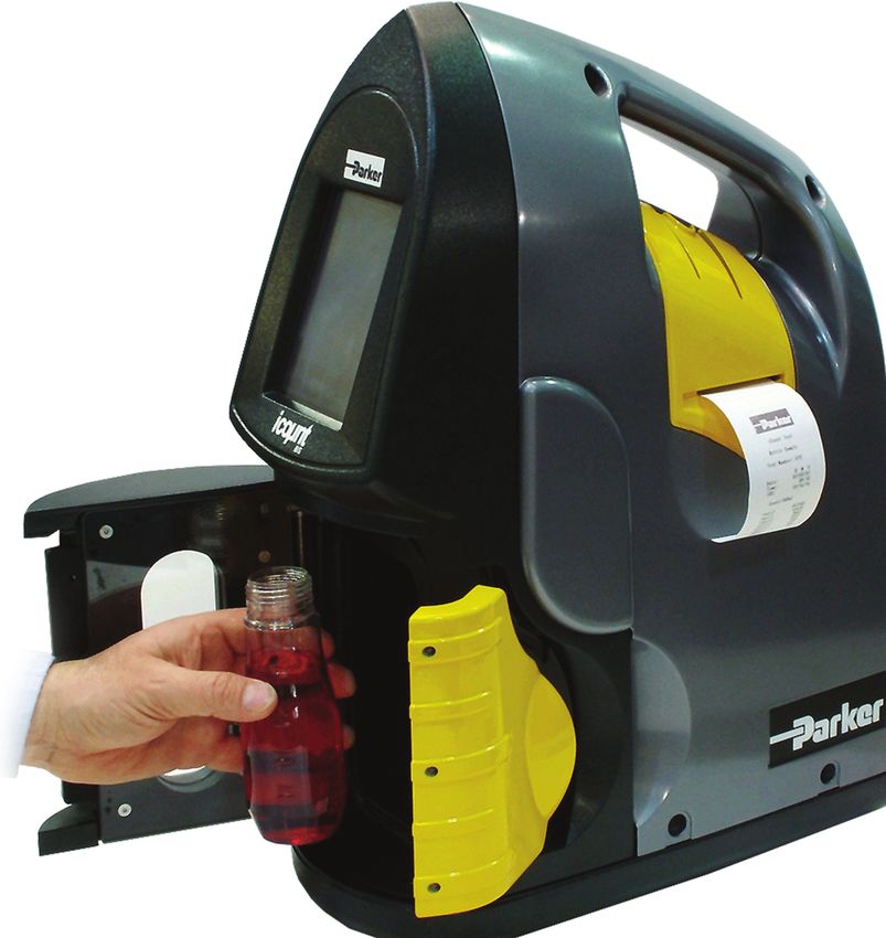
Condition Monitoring Products & Custom Solutions

The Parker Hannifin Hydraulic, Lubrication &
Coolant Filtration
Filtration Group assures: High-performance filtration
systems for production
machinery in industrial, mobile
n Consistent quality and military/marine.
n Technical innovation
n Premier customer service Compressed Air &
Gas Filtration
Complete line of compressed
Parker’s technical resources provide the air/gas filtration products;
coalescing, particulate and
right filtration technologies that adsorption filters in many
applications in many industries.
conform to your requirements. That’s why
thousands of manufacturers and
equipment users around the world rely on
Process & Chemical
Parker Filtration products and people. Fluid Filtration
Liquid filtration systems for bever-
age, chemical and food processing;
cosmetic, paint, water treatment;
photo-processing; and micro-chip
Worldwide Sales fabrication.
and Service
Parker operates sales and service
Fuel Conditioning
centers in major industrial areas & Filtration
Parker air, fuel and oil filtration
worldwide. Call 1-800-C-PARKER systems provide quality
protection for engines operating
for more information and for in any environment, anywhere
in the world.
a synopsis of our Filtration
Technology Textbook.
Legal Notifications
! WARNING
FAILURE OR IMPROPER SELECTION OR IMPROPER USE OF THE PRODUCTS AND/OR SYSTEMS DESCRIBED HEREIN OR RELATED ITEMS CAN CAUSE DEATH, PERSONAL INJURY AND
PROPERTY DAMAGE.
This document and other information from Parker Hannifin Corporation, its subsidiaries and authorized distributors provide product and/or system options for further investigation by users
having technical expertise. It is important that you analyze all aspects of your application and review the information concerning the product or system in the current product catalog. Due
to the variety of operating conditions and applications for these products or systems, the user, through its own analysis and testing, is solely responsible for making the final selection of
the products and systems and assuring that all performance, safety and warning requirements of the application are met.
The products described herein, including without limitation, product features, specifications, designs, availability and pricing, are subject to change by Parker Hannifin Corporation and
its subsidiaries at any time without notice.
Offer of Sale
The items described in this document are hereby offered for sale by Parker Hannifin Corporation, its subsidiaries or its authorized distributors. This offer and its acceptance are governed
by the provisions stated in the “Offer of Sale”.
© Copyright 2014, Parker Hannifin Corporation, All Rights Reserved.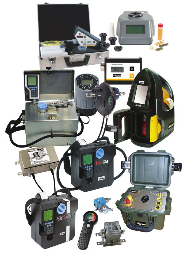
Content

  icountLCM20 Contamination Monitor........................................................ 1
  icountACM20 Lab Unit................................................................................. 6
  Universal Bottle Sampler........................................................................... 9
  icountSBSBottle Sampler...........................................................................13
  Single Point Sampler................................................................................. 19
  System 20 Sensors and Monitors.............................................................. 22
  icountPD and icountPDZ.......................................................................... 27
  icountOS...................................................................................................... 36
  Moisture Sensor Range............................................................................. 47
  Oilcheck Monitor........................................................................................ 53
  ANALEXfdMplus......................................................................................... 57
  DIGI Field Kit ..............................................................................................58
  Low Range DIGI Water Kit..........................................................................59
  Heated Viscometer..................................................................................... 60
  MHC Bearing Checker................................................................................ 61
  Guide to Contamination Standards............................................................62
  Offer of Sale................................................................................................ 67
Introduction
  Parker Hannifin is comprised of eight global groups:              Quality Is Top Priority
  Aerospace, Climate & Industrial Controls, Fluid                   Parker Filtration has had a total quality management
  Connectors, Seal, Hydraulics, Filtration, Automation              system in place for years, as well as a Director of Corporate
  and Instrumentation.                                              Quality for all of Parker. This structure helps us continually
                                                                    meet our customers’ expectations for the highest technical
  The Filtration Group consists of ten technical sales              standards, reliable supply and responsive service. From the
  and service locations: Finite Filter, Hydraulic Filter            Group President on down, “Quality” at Parker means more
  Division North America, Hydraulic Filter Division                 than making a product the right way. Quality permeates
  Europe (two locations), Process Filter, Racor,                    our whole organization so that every employee thinks
  Parker Hannifin Brazil and Parker Hannifin Korea.                 about what he or she does and what is expected by our
                                                                    customers.

  Customer Support Information
  Technical Support You Can Count On
  Parker’s technical resources assure you of the right
  filtration technologies, advanced designs, consistent
  manufacturing and a network of helpful, specialized
  professionals trained to support your team.

  We listen to you; then we design the right filtration solution.
  Parker holds over 150 patents on innovative filtration            “Always Available”
  products, including filtration membranes, differential            Customer Service
  pressure indicators, cartridge bypass valves and spin-in
  elements.                                                         Parker Filtration
                                                                    distributors provide
  Parker Filtration makes the technological investments             local stock and
  needed to assure the highest quality products. Examples           technical design help
  are modern clean rooms, sophisticated testing equipment,          including 24-hour
  CAD/CAM engineering, and CNC integrated equipment that            emergency service.
  is helping us design tomorrow’s filtration products today.        They are further
                                                                    supported by our “ever
                                                                    ready” manufacturing
                                                                    teams.

                                                                    So if you need more technical literature or applications
                                                                    support please call us toll free at 1-800-253-1258 or at our
                                                                    24 hour corporate help line at 1-800-C-PARKER.

                                                                    		 Parker Hannifin Corporation
                                                                       Hydraulic Filter Division
                                                                    		 16810 Fulton County Road #2
                                                                    		 Metamora, OH 43540
                                                                    		 Toll Free: (800) 253-1258
                                                                    		 Phone: (419) 644-4311
                                                                    		 Fax: (419) 644-6205
                                                                    		http://www.parker.com/hydraulicfilter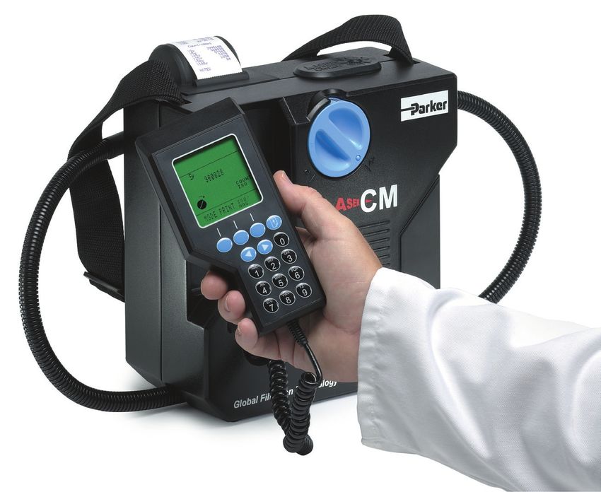
icountLCM20
Fluid Condition Monitoring
Portable Particle Monitor
Typical Applications
• Construction machinery
• Industrial plant
• Hydraulic equipment & system
  manufacturers
• Research & testing institutes
• Offshore & power generation
• Marine
• Military equipment
  applications

icountLCM20 is a proven answer      Unusually, the move from fixed          On-line APCs must be able to
to fluid system contamination       laboratory use, to portable field       test the oil sample at whatever
monitoring. Multi-standard ISO      use has not been at the expense of      cleanliness it is delivered to the
and NAS cleanliness reporting,      accuracy or user flexibility, but has   machine. Parker therefore had
data entry, data graphing           actually enabled the instruments        to develop technology to ensure
and integral printing are all       to be used over a wider range of        the on-line APC was able to test a
standard on this world proven       applications and situations.            sample without the conventional
contamination monitor.                                                      laboratory technique which
                                    The most common monitoring
                                                                            requires dilution - a practice
Automatic Particle Counters         technique used in APCs is that
                                                                            that would have been simply
(APC), have been widely used        of light obscuration or light
                                                                            impossible with a portable unit.
for many years in condition         blockage. Here, a focused light
monitoring of hydraulic fluids.     source is projected through a           By careful design and window
However, it is only recently        moving column of oil, (in which         sizing, 40,000 particles per ml can
that APCs have become flexible      the contaminants being measured         be achieved without making the
enough to enable the instruments    are contained), causing an              instrument susceptible to counter
to be taken out of the laboratory   image of the contaminant to be          saturation.
and used on-line in order to        projected on to a photo diode cell,
obtain the most credible form of    (changing light intensity to an
results.                            electrical output).
                                    The electrical output of the photo
                                    diode cell will vary in accordance
                                    with the size of the particles
                                    contained in the column of oil;
                                    the larger the particle, the bigger
                                    the change in the photo diode
                                    electrical output.

                                                     1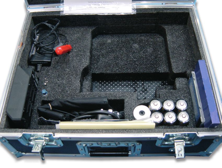
icountLCM20
Features & Benefits

 Test time                         2 minutes
                                   MTD 4+, 6+, 14+, 21+, 38+ and 70+ microns(c)
 Particle counts
                                   ACFTD 2+, 5+, 15+, 25+, 50+ and 100+ microns
 International codes               ISO 7-22, NAS 0-12
 Data retrieval                    Memory access gives test search facility
 Max. working pressure             6000 psi (420 bar)
                                   106 gpm (400 lpm) when used with system 20 Sensors. Higher with
 Max. flow rate
                                   single point sampler
 Working conditions                LCM will operate with the system working normally
 Computer compatibility            Interface via RS232 connection @ 9600 baud rate.

• Special ‘diagnostics’ are            of up to 300 tests can be          • Limit level output to control
  incorporated into the                selected via hand set display.       peripheral equipment such as
  icountLCM microprocessor           • Totally portable, can be used        off-line filtration via internal
  control to ensure effective          as easily in the field as in the     relay limit switches.
  testing.                             laboratory.                        • Auto-testing allows for the
• Routine contamination              • Automatic calibration                conducting of automatic
  monitoring of oil systems with       reminder.                            sequencing tests on flushing
  icountLCM saves time and                                                  systems for example.
  saves money.                       • Instant, accurate results
                                       achieved with a 2 minute test      • Memory access gives search
• Contamination monitoring             cycle.                               facility.
  is now possible during                                                  • Worldwide service and
  application operation              • Data entry allows individual
                                       equipment footprint record.          technical support.
  - icountLCM saves on
  production downtime.               • Data graphing selectable via       • Re-calibration - Annual
                                       the integral printer.                certification by an approved
• Data entry allows individual                                              Parker Service Center.
  equipment test log details to      • Auto 300-test cycle logging via
  be recorded.                         LCD handset input.
• Data retrieval of test results     • RS232 to USB computer
  from memory via hand set             interface.
  display.
• Automatic test cycle logging

                                                      2
icountLCM20
Specifications

                                                                                               (1.26)
Description                                                 LCM20.2022 LCM20.2062

                                                                                                 32
ABS structural foam and injection molded
                                                                 •              •
case

                                                                                                    126 (5)
ABS handheld display                                             •              •
Mechanical composition – Brass,
                                                                 •              •
plated steel, stainless steel and aluminium
Fluorocarbon seals                                               •

                                                                                               (1.1)
                                                                                                29
Perfluoroelastomer seals                                                        •
Nylon hoses (kevlar braided microbore)                           •              •
Stainless steel armoured hose ends                               •              •

                                                                                                    249 (9.8)
4 ft (1.2m) fluid connection hose                                •              •
Rechargeable battery pack                                        •              •
12Vdc power supply                                               •              •
Fast blow fuse                                                   •              •
                                                                                                                                240 (9.4)
Unique optical scanning system                                   •              •
Bonded glass optical window enclosed in
                                                                 •              •
SS plate
Micron channels analysis to 5 measured
                                                                 •              •
channels and the sixth channel is calculated.
Analysis range ISO 7 to 22 incl. (NAS 0 to
                                                                 •              •
12)
32 character dot matrix LCD. Alpha numeric
                                                                 •              •
keypad
Data retrieval                                                   •              •
Calibration - see note below                                     •              •
Viscosity range 2 to 100 cSt. 500 cSt.with                                                                                                      dimensions in mm (inch)
                                                                 •              •
SPS
Operating temp. 41°F to 176°F (+5°C to
+80°C)
                                                                 •              •
                                                                                           Accessory Kit - icountLCM Classic
Ambient temp. 41°F to 104°F (+5°C to
                                                                 •              •
+40°C)                                                                                                          Limit socket, fuse                            ParSmart &
2 minute test completion time                                    •              •      Power supply                & jack plug              Screwdriver       cable assy

Memory store – 300 test memory                                   •              •
Battery operated 6 x 1.5 D cells                                 •              •
Phosphate Ester group compatibility                                             •
Mineral oil & petroleum based fluid
                                                                 •              •
compatibility
Up to 6000 psi (420 bar)                                         •              •
Integral 16 column printer                                       •              •
RS232 to USB computer interface
Astra board case weight – lb (Kg)                             11 (5)          11 (5)
Unit weight – lb (Kg)                                        17.6 (8)       17.6 (8)
ParSmart software and cable link pack                            •              •
Weather protector cover                                          •
CE certified                                                     •              •
Auto logging                                                     •              •
The LCM and calibration master sample the same particle distribution suspension.       Re-chargeable               Instruction            Power lead,
                                                                                                                                                                 Batteries &
The LCM is calibrated to the master to meet specification at the measured points.       battery pack             manual & bar            printer ribbon,
                                                                                                                                                                 printer reel
MTD – instrument calibrated using MTD reference material.                                                        code software          bar code pen &
ACFTD – instrument calibrated using ACFTD reference material.                                                                           weather cover
Consult Parker for recalibration.

                                                                                       3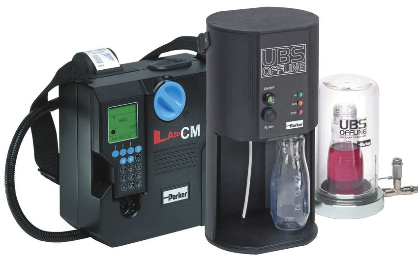
icountLCM20
icountLCM Proven Core technology
The icountLCM portable particle monitor features microprocessor
controlled optical scanning for accurate contaminant measurement with
a calibration range from ISO 7 to ISO 22 with no counter saturation.

How does icountLCM work?
• The particles are measured by a photo diode that converts light          Laser Optical Sensing
  intensity to a voltage output which is recorded against time.
• As the particle moves across the window the amount of light lost
  is proportional to the size of the particle. This reduction in voltage
  is measured and recorded.
• This reduction in voltage relates directly to the area of the particle
  measured.
• This value is counted and stored in the icountLCM computer in
  one of 5 measured channels according to particle size.
• Readouts are displayed on the hand-held LCD in the accepted
  ISO and NAS standards ready for hard copy printing or RS232
  computer download.
• The on-board computer allows storage of up to 300 test results.

Why On-Site Fluid Contamination Monitoring?                                A focused light source is projected
                                                                           through a moving column of oil.
• Certification of fluid cleanliness levels.
• Early warning instrument to help prevent catastrophic failure in
  critical systems.
• Immediate results with laboratory accuracy.                              Data Download
• To comply with customer cleanliness requirements and                     Management
  specifications.
• New equipment warranty compliance.                                       Dedicated software, provides the
• New oil cleanliness testing.                                             link between an icountLCM20
                                                                           and your computer management
                                                                           system.

                                                                                         icountLCM Test
                                                                                          ON LINE TEST
                                                                                       TEST NUMBER 022

                                                                                                      D M Y
                                                    icountLCM Test                  Date            04-03-10
                                                                                    Time               15-52
                                                    ON LINE TEST                    NAS CLASS:             7
                                                TEST NUMBER 022                           Count / 100ml
                                                                D M Y               4/6µ (c)         789157
                                             Date             04-03-10
                                             Time                15-52              6/14µ (c)         31250
                                             ISO:             20/15/09              NAS CLASS             7
                                                                                    14/21µ (c)          250
                                                    Count / 100ml                   NAS CLASS             3
                                                                                    21/38µ (c)           50
                                             >4µ (c)            820721              NAS CLASS             3
                                             >6µ (c)             31564              38/70µ (c)           14
                                             >14µ (c)              314              NAS CLASS             4
                                             >21µ (c)		             64              >70µ (c)		            0
16-column printer for hard copy data. A      >38µ (c)		             14              NAS CLASS             0
                                             >70µ (c)		              0
feature of the icountLCM is the on-board
                                                                                    NOTES
printout data graphing option developed      NOTES
to support predictive maintenance
procedures.                                     ISO 4406 - 1999                     Correlation to NAS 1638

                                                          4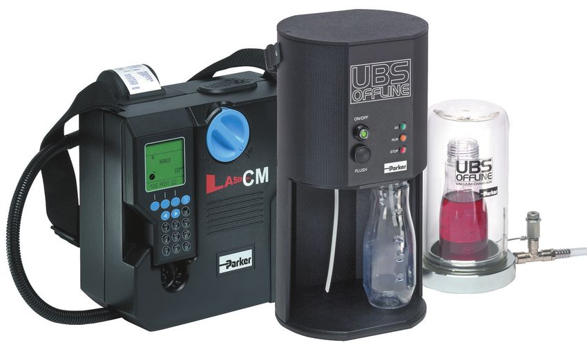
icountLCM20
Ordering Information

  Model              Fluid Type                       Options
 LCM2020         2    Hydraulic Mineral      1   icountLCM20 (ACFTD calibrated)
                 6         Skydrol           2    icountLCM20 (MTD calibrated)

   Part Number               Supercedes                   Description
   ACC6NE015                      B84702                 Printer roll x 5
   ACC6NE014                      P.843702               Printer Ribbon
   ACC6NE013                      B84609           Re-chargeable battery pack
   ACC6ND002                      P849603           Weather protector cover
   ACC6ND000                      B84703         USB to RS232 download cable

                                             5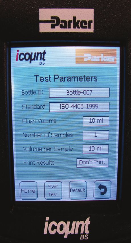
icountACM20
Aviation/Diesel Fuel Condition Monitoring Lab Unit
State-of-the-Art Fuel Contamination Monitoring
The icountACM20 Portable Particle Counter was developed from
existing technology for monitoring contamination in AVTur and other
hydrocarbon fuels, in accordance with Energy Institute (EI) Method IP
564.

In addition, the ACM can also be used to monitor fuels from existing
sampling points in locations from refineries, pipelines, distribution
terminals, fuel supply storage.

Features and Benefits
y 2 minutes test time                  y On-board battery and carry
y Optical scanning analysis              case with wheels (13 kg total
  and measurement of actual              weight)                          Applications
  particles and inference to           y 12v DC input, 6 “D” cell         y Fuel Testing Laboratories -
  water presence                         batteries or rechargeable          DEFSTAN 91-91 Issue 6
y Primary outputs: 4, 6, 14, 21,         battery pack                     y Distribution Terminals/Hubs:
  25, 30μ counts per ml                y Integrated 16 column printer       use on receipt and outbound
y % Volume distribution, via             for hard copy data                 supply. Also provide checks
  graphical display on handset         y Complies with all relevant EC      for filtration performance, tank
  and printout                           declarations of conformity         cleanliness and product quality
y ISO 7-22 in accordance with          y Integrated Mounted Pump:         y Storage: reduce settling time
  ISO 4406-1999                          - Powered directly from            by monitoring to determine if
y 32 Character two line dot                ACM20                            dispersed contamination are
  matrix LCD. Full alphanumeric          - Direct sampling from fuel        below acceptable levels
  entry facility on keypad                 sample bottles or tank via 3   y Airport Fuel Farm: monitoring
y Access up to 300 saved test              meter inlet suction tube         of fuels into storage, through
y The instrument shall be                - Incorporated double speed        fuel farm, hydrant system and
  certified as being calibrated            flush and test sequence          during uplift into wing
  with a working standard test           - Managed flow rate/correct      y Oil and Gas Platforms: monitor
  dust suspension verified                 volume sample as per IP 564      filtration performance, system
  against an ISO 11171                     test method                      cleanliness and quality of
  secondary calibrated master                                               delivered product
  APC.
y Re-calibration every 12
  months by a dedicated Parker
  Service Center
y 420 bar Max. Working
  Pressure
y +5° C to +80° C
y Interface via RS232 (USB
  serial cable to RS232 option
  available)
y On-board rear mounted pump
  for lab sampling

                                                        6
icountACM20
Specifications
• Construction: ABS structural icountACM20 - Rear View
foam and injection moulded
case
Hand-held display - ABS Transfer Pump
Keypad flurosilicone rubber Transfer Pump On/Off Switch
• Mechanical Components: Flush Button Link Hose
Brass, plated steel, stainless (Fixed to dummy
steel and aluminium connector for
• Seals: Fluorocarbon storage)
• Hoses: Nylon (Kevlar braided
microbore). Stainless steel
armoured ends
• Flow Rate: 25 - 28ml/min
(dictated by CMP) 100ml/min
with additional flush button
• Fluid Compatability:
Hydrocarbon Fuel, Mineral Oil.
For other fluids consult Parker Sample
• Fuse: 1.25 amp fast blow Hose Inlet
fuse included for overload and Outlet
protection (spare supplied) Transfer Pump
• icountACM20 Technology: Housing
Patented flow cell, light
obscuration Hose Tidy Clips
• Coincidence: 40,000 particles
per ml
• Viscosity Range: 1 -100 Input Power Socket (note that you will have to remove the plastic
centistokes dust cap to access the 12Vdc power socket)
• icountACM20 Weight: 17.6
lbs. A fast blow 1.25A fuse and the RS232 connection are located behind
• Monitor Carrying Case: Astra the removable cover plate. The RS232 interface is provided to
Board case download all test data stored in the instrument.
• Carrying Case Weight: 11 lbs.
Field Monitoring
For use in non-hazardous areas,
the icountACM20 is designed for
online sampling of hydrocarbon
fuels, utilizing existing “quick
connect” sampling points such
as the Millipore Adaptor.
7icountACM20
Part Number Description Part Number Description
icountACM20
ACM202024US Portable Particle UK Battery
ACC6NE023
ACM202024UK Counter Charger
ACM202024EU with US,UK or
EU Plug
EUR Battery
ACC6NE024
Charger
UK Power
ACC6NE008
Supply
US Battery
ACC6NE025
Charger
EUR Power
ACC6NE009
Supply
ACC6NW003 Waste Bottle
US Power
ACC6NE010
Supply
1m Process Re-Chargeable
ACC6ND000
Cable Assembly ACC6NE013 Battery Pack
Assembly
2m Process
ACC6NE027
Cable Assembly
Downloadable
ACC6NE006
Software
ACC6NE029 Throttle Kit Carrying Case
ACC6NE019
for ACM202024
Carrying Case
ACC6NE028
for ACM202032
Printer Paper
ACC6NE015
5 Rolls
Vapor/Waste
ACC6NW003
Bottle
500ml
SERMISC067
Verification Fluid Printer
ACC6NE014
Ribbon
8Universal Bottle Sampler
Simple and efficient offline oil sampling
Ideal for batch oil
sampling
The UBS provides the dynamic
link to portable particle counters.
The UBS off-line sampler has
microprocessor technology
to recognize and adjust to the
connecting monitor including the
icountLCM20.
Product Features
Simple operation
Efficient testing procedure
Clean and contamination free sampling
Available for both mineral based and aggressive fluids
Further advances the LCM20’s flexibility into laboratory
bottle sampling environments
Can accept various different sized bottles
Minimal working parts
Internal auto setting fuse for overload protection
Simple maintenance procedures
9Universal Bottle Sampler
Specifications
Description UBS Offline
Viscosity range 2 to 250 cSt X
Operating temp. 41°F to 176°F (+5°C to +80°C) X
Test time 2m15s / 4m15s (Flush 2m) X
12 Vdc power supply X
Extruded aluminium construction X
Unit weight - (lb.) 8.82
Mineral oil and petroleum based compatibility Fluorocarbon seal
Phosphate Ester group compatibility EPDM seals
CE certified X
Military approved X
Manual operation X
Bottle pack X
De-gassing chamber X
Manual X
Sample tube pack X
Interface cable to LCM20 X
Installation Details
12.6 (319mm)
5.94 (151mm)
5.79 (147mm) 6.5 (165mm)
7.05 (179mm) 4.72 (120mm) CTRS
.433 (11mm)
3.15 (80mm) CTRS
3.94 (100mm) CTRS
dimensions in inch (mm)
10Universal Bottle Sampler
Simple and Efficient Offline Oil Sampling
System Flow Rate
Samples are best taken from a point in the system
where the flow is TURBULENT (Reynolds No. greater
than 4000). The turbulent flow creates a mixing
action. Where flow is streamline or LAMINAR, larger
particulate may tend to settle toward the lower pipe
surface and not be sampled.
System Condition Changes
Changes in the system operating condition, flow,
temperature, pressure or vibration, can result in
previously sedimented contaminant being retrained
Sampling points should enable extraction of a sample
into the flowing oil. It is also possible that these
without changing the system’s condition. Fine control
changes may cause partially contaminated filter
needle valves are not desirable, as they have a
elements to shed particulate into the system. Samples
tendency to silt up under some operating conditions,
should, therefore, be extracted when the system is in
causing the distribution of contaminants in the fluid to
a steady state condition and the result less likely to
be changed. The sampling port should be protected
be distorted by contaminant peaks.
to maintain cleanliness and thoroughly flushed before
There are a number of proprietary sampling valves collecting the sample for analysis. Allow sufficient
available which adhere to good theoretical principles. airspace in the bottle to enable 80% fill.
However, they do tend to generate a level of precision
and cost which is unnecessary for trend monitoring.
Bottle Cleanliness
It is preferable that bottles have sealing screw caps
and both parts are cleaned to a suitable level in
accordance with ISO3722.
Standard Parker bottles are supplied clean to
ISO15/13/10 (NAS Class 4).
The bottle should remain capped until time of sample
filling and re-capped immediately afterwards.
Sample Mixing
Sedimentation of contaminant in a sample will occur,
the rate of which is dependent upon both fluid and
particle characteristics.
Samples should be analysed, without delay, once
agitated and de-gassed.
ACC6NW001 x 50 = ACC6NW002 ACC6NK001
11Universal Bottle Sampler
Ordering Information
Standard products table
Part Number Description
UBS9002 Universal Bottle Sampler/mineral oil (includes aluminium case and accessories)
UBS9005 Universal Bottle Sampler/aggressive fluid (Includes aluminium case and accessories)
Accessories
Part Number Supersedes Description
ACC6NK001 B89907 Sample bottle (2/pack)
ACC6NW001 B89911 Sample bottle with extraction hose (2/pack)
ACC6NW002 B89910 Sample bottle with extraction hose (50/pack x 2)
ACC6NK002 S840054 UBS power supply
ACC6NK003 S890005 UBS degassing chamber and pump
ACC6NK004 B89603 UBS degassing chamber only
ACC6NK005 B89902 Cable and adaptor
Note 1: Part numbers featured with bold highlighted codes will ensure a ‘standard’ product selection.
Note 2: Alternate displayed part number selection will require you to contact Parker Filtration for availability.
Typical Applications
Batch sampling
Aircraft rig certification
Oil research
Laboratory testing
Transfer line monitoring
12icountBS - Bottle Sampler
The benchtop solution to fluid contamination
bottle sampling
13The Complete Solution - Industrial
Design Combined with State of the
Art Technology
The icountBS - Bottle Sampler from
Parker, with its innovative industrial
The IBS features an easy to
use interactive touch screen,
icountBS - Bottle
design, has been developed for
customers looking for state of
environmentally controlled pressurized
bottle chamber, an internal
Sampler Features &
the art technology, attention to compressor pump, automated door Benefits
detail and the compactness of locking mechanism, sample tube
a permanent laboratory particle cleaning sleeve that minimizes cross • Customer programmable number
analysis instrument. contamination, and an internal printer. of sample runs/sample bottle
averaging and pre-test flush
Combine this with on-board, laser The icountBS benefits from Parkers volumes from 10ml min. to 100ml
based, leading edge technology knowledge and experience of max.
to bring to all industries a truly providing fluid analysis equipment to
revolutionary Particle Counter. The the market for over 15 years. • Input via fluid resistant touch screen
innovative icountBS is a product display.
from the next generation of Parker’s
fluid particle analysis and monitoring • Repeatable and reproducible
solutions. performance to ISO4406:1999,
AS4059 Rev E, and NAS1638 particle
count distributions. Other calibration
standards are included.
• On-board compressor and ‘shop’ air
capable.
• Design concept allowing for
portability. DC and rechargeable
battery pack options built in.
• Sample tube self cleaning sleeve
minimizing cross contamination.
• 500 test sample memory.
• Data download via USB jump drive
or USB to USB included.
• Internal printer.
14Home Screen Sample ID Input Number of Sample Runs
Sample Volume Flush Volume Start Test
15Analyzing the Test Results
Once the automatic oil levels relating to three sizes. 1,300 - 2,500 particles that
sample test has been The first scale number are equal to and greater than
completed, what next? represents the number of 6μm(c), and between 80 - 160
particles that are equal to and particles that are equal to and
Solid contaminants in fluid greater than 4μm (c) per ml of greater than 14μm(c).
power systems vary in size, fluid, the second number for
shape, form and quantity. The particles that are equal to and
most harmful contaminants greater than 6 μm(c) per ml of
are normally between 6 fluid and the third number for
microns and 14 microns. The particles that are equal to and
ISO code is the preferred greater than 14 μm(c) per ml
method of reporting quantity of fluid.
of contaminants.
For example: An ISO code
The ISO code number 20/18/14 indicates that there
corresponds to contamination are between 5,000 - 10,000
particles that are equal to and
greater than 4μm(c), between
16icountBS Product Specification
Principle of Operation Laser based light obscuration
Dimensions H=20.9” x W=7.48” (8.27” Door) x D=16.1”
Weight 31 lb. (14kg)
Mechanical Composition Stainless steel 316, plated mild steel and aluminum
Plastics Composition Precision polyurethane RIM moldings and ABS plastic
Environmental Operating Temperature
41°F to 140°F (+5°C to +60°C)
(Tested)
Operating RH Range 20 - 85% [Tested at 86°F (30°C), no condensation]
Storage Temperature 40°F to 194°F (-40°C to +90°C)
Storage RH Range 10 - 90% (Tested at 30°C, no condensation)
MTD - >4μ(c), >6μ(c), >14μ(c), >21μ(c), >38μ(c), >70μ(c), ACFTD - >2μ, >5μ, >15μ,
Channel Sizes
>25μ, >50μ, >100μ
Analysis Range ISO 7 to 21, NAS 0 to 12
MTD - ISO 4406:1999 & NAS 1638 ACFTD - ISO 4406:1987, ISO 4406:1991, NAS
Contamination Standards 1638, and AS4059 Rev E
For further contamination standards consult Parker
ISO MTD and ACFTD calibration to traceable ISO Standards. (Contact Parker for
Calibration Standard
further details)
Fluid Management Maximum single sample = 100ml, Minimum single sample = 10ml
User selectable from single test up to 5 tests per run (eg. 1 x 100ml up to 5 x 50ml
Possible Test Configurations
per run)
Pre-Test Flush Volume Minimum = 10ml, Maximum = 100ml
Viscosity Range 5 to 400 cSt
Mineral oils, petroleum and hydrocarbon based fluids. For all other fluids, consult
Fluid Compatibility
factory.
No specific bottle required. Maximum size = 2.95” (Dia.) x 5.90” (H). Maximum
Sample Bottle Size
volume = 250ml
Memory Storage 500 tests (capacity warning after 450 tests)
Output Display Backlight 256 color STN transmissive
Output Display Resolution 320 x 3 (RGB) (H) x 240 (W) dots
Display Active Area 115 (H) x 86 (W) mm
Data Input Via icon driven resistive touch screen
Printer Thermal dot-line printing
Printer Paper Ø50mm - (57mm x 25mm)
Test Certification Calibration & Certificate of Conformity
DC output - 12V @ 6.60Amps, 80 watts max. AC input - 100 to 240V @ 1.2Amps (50
Power Supply
- 60 Hz)
Battery Power 2 hours (recommended to be fully charged every 3 months)
Battery Stand-By Time 1 month (then 1 hour of operation)
Battery Fuse 6.3 Amps (anti-surge)
Air Pressure Source 50 psi (3.5 bar) internal mini-compressor or 101 psi (7 bar) shop air
17icountBS - Bottle Sampler Ordering
Information
Part Number
IBS3000 (offline/online)
IBS3100 (offline only)
Accessories Part Number Included
250ml Sample Bottle (2 per pk) ACC6NW001 * (1 pk)
Sample Bottle Pack (50) ACC6NW002 (2 pks of 50)
Vapour/Waste Bottle ACC6NW003 *
Waste Bottle Folder ACC6NW004
Printer Paper Reel (x1) ACC6NW005 *
Transport Case P893865 *
1m Waste Tube (Clear) ACC6NW009 *
1m Vapour Hose (Blue) ACC6NW010 *
USB Memory Stick ACC6NW011 *
icountBS CD Manual ACC6NW012 *
Air Connector P.893318 *
* These items included with IBS unit within a transportation case.
18Single Point Sampler
Online Sampling
The effective link
to ensure accurate mineral based fluids
contamination
monitoring
The SPS (Single Point Sampler) is
a lightweight, compact and easy
to use online sampling unit that
connects an icountLCM20 to a single
pressure test point in a fluid system.
Suitable for use with mineral and
biodegradable oils, petroleum based
and phosphate ester fluids, the SPS
offers fingertip operated control even
at high pressures - 6,000 PSI (420
bar) rated maximum pressure.
phosphate ester fluids
Product Features:
• Lightweight, compact and easy to use online sampling unit.
• Connects an icountLCM20 to a single pressure test point in
a fluid system.
• Suitable for use with mineral and biodegradable oils,
petroleum based and phosphate ester fluids.
• 6,000 PSI (420 bar) rated maximum pressure
19Single Point Sampler
Features & Benefits
The Single Point Sampler provides a Suitable for fluid temperatures from +5°C to
means to connect an icountLCM20 to a +80°C (+41°F to +176°F)
single pressure test point and balance the High quality polished finish. (stainless
differential pressure across the system, steel/ aircraft grade aluminium)
to provide a controlled flow of oil into the Capable of working with an icountLCM20
icountLCM20 and away into a waste oil connected into a system via the standard
receptacle. one metre extension hose kit
Lightweight, compact and easy to use Suitable for use with mineral and
design biodegradable oils, petroleum based and
Fingertip operated control valve even at phosphate ester fluids
high pressures Phosphate ester version utilizes the 5/8”
6,000 PSI (420 bar) rated BSF HSP style fitting
Facilitates testing from large diameter Designed so that it meets the lowest
pipework possible level of magnetic permeability
Capability to test up to 500cSt viscosity Supplied with accessories kit
oils (pressure permitting) It will maintain the set flow rate between
Pressure compensated flow control upper and lower limits within a 100 bar
mechanism inline pressure change
Possible to control the valve with the Clear product identification to ensure that
same level of accuracy whether the it is connected correctly (i.e. downstream
device is operating at high or low pressure of the icountLCM20).
Capable of allowing a flow rate in excess
of 10ml/min when operating at any
viscosity within the product specification
Connection Instructions
1. Ensure valve is closed (A).
System 2. Connect P2 on icountLCM20 to P2 on Single Point Sampler (SPS) (C).
3. Connect drain line on SPS (D).
(F) (D) 4. Connect P1 of icountLCM20 to the system (F).
Prs.
R 5. The SPS is ready to operate.
6. Open valve (A) slowly until the oil flows continuously from the drain line
(A) (D) into a reservoir or receptacle (R).
Single 7. Switch on monitor and begin testing.
point
sampler icountLCM20 Only
(C) Carry out flow test as shown in the manual. If test is showing below Dt
38.5°F (3.6°C) then carry out test as normal. If, however, test is above Dt
(E) P1 P2 (B) 38.5°F (3.6°C) then increase oil flow by turning valve (A) counterclockwise
and then carry out flow test. Do this until Dt is below 38.5°F (3.6°C) and
carry out test as normal once achieved.
WARNING! Ensure that SPS valve is closed and icountLCM20 is
icountLCM20
connected to the SPS BEFORE connection to system.
20Single Point Sampler
Specifications
Fluid Compatibility:
Mineral oil and petroleum based fluids
Phosphate ester fluid
For other fluids consult factory
Seals:
Fluorocarbon or Perfluoroelastomer 4.84 (123mm)
Maximum Working Pressure:
6,000 PSI (420 bar)
2.09 (53mm)
Weight:
500 grams max. (Not including hoses) SWP 6,000 psi
Unit Size:
1.77in dia x 4.8in long (45mm dia x 123mm long)
System Connection: 3.15 (80mm)
Mineral petroleum fluids - M16 (G1/4” BSP) with cap,
Phosphate ester - 5/8” BSF HSP
Operating Temperature Range:
+41°F to +176°F (+5°C to +80°C) P2
Storage Temperature Range:
-15°F to +176°F (-26°C to +80°C)
Construction: Ø1.77 (45mm)
Body: Aluminium BS 1470 – pressurized end stainless steel
Finish: Anodized blue - Mineral fluid
Anodized red - Phosphate ester fluid
dimensions in inch (mm)
Ordering Information
Standard products table
Part Number Supersedes Description
SPS2021 SPS.2021 Single point sampler (mineral fluids)
SPS2061 SPS.2061 Single point sampler (phosphate ester fluids)
ACC6NW003 B84784 Waste bottle (Universal)
ACC6NH001 B84224 Extension hose/coupling (mineral fluids)
ACC6NH002 B84225 Extension hose/coupling (phosphate ester fluids)
ACC6NH003 B84788 Waste hose (mineral fluid)
ACC6NH004 B84787 Waste hose (phosphate ester fluids)
Note 1: Part numbers in bold are ‘standard’ product selection with all accessories.
21System20
Inline Sensors & Monitors
Effective in-line
system sensors
and monitors
In-line System20 sensors and
hand-held monitors designed to
give accurate and instant fluid
system readings of flow, pressure
and temperature. 3 sizes of inline
System20 sensor for pressures up
to 6,000 PSI (420 bar), an analog
monitor that utilizes 3 day-glow
gauges with protective cover. EM20
electronic monitor with full digital
display and 300 test memory.
Product Features
• 2 types of System20 sensor are available.
STI = industrial with reverse flow capability.
STS = mobile without reverse flow capability.
• 3 sizes of industrial inline System20 sensor for pressures
up to 6,000 PSI (420 bar). 2 sizes of Mobile System20
sensor.
• Analog monitor utilizes 3 day-glow gauges with protective
cover.
• EM20 electronic monitor with full digital display and 300
test memory.
• For use with all mineral oils, water and oil/water emulsions.
22System20
Features & Benefits
Covering a wide range of flow rates, fluid types
and applications, Parker’s System 20 sensors
are designed to be used with System 20
electronic or analog monitors, icountLCM and
the icountPD. Specially developed System20
sensors are available for use with phosphate
ester fluids (EPDM Seals).
System20 monitors, combined with the inline
sensor, give the user accurate and instant
readings of flow, pressure and temperature
without the need for costly system downtime.
For use with all mineral oils, water and water/
oil emulsions.
Analog Monitor (STM)
Utilizes 3 Day-Glo dial gauges with a
protective hinged cover.
Industrial STI family
Calibrated up to 100 gpm with dual scale PSI/
bar & °F/°C. (USGPM also available)
Electronic Monitor (EM20)
Gives a full digital display.
Automatically calibrated for all 3 sizes of
sensor.
Indicates line, differential and rising peak
pressure.
Easily scrolled from metric to US.
300 test memory.
Capable of downloading saved data to
download software.
Typical Applications
Drilling equipment
Mining
Grinding and conveying
Industrial hydraulics
Mobile applications
2 sizes of System20 Inline Mobile Sensors are available
Hydraulic system users need to ensure that lost
production is kept to the absolute minimum.
To ensure this, predictive maintenance utilizing
routine condition monitoring of hydraulic systems
is essential.
23System20
Specifications: Sensors
Construction:
Industrial: (STI)
Body: 303 SS
Internal components: SS and Brass
Mobile: (STS)
Body: 303 SS
Internal components: Cast Aluminium
and SS
Flow Capacities:
All suitable for use with oil, water and
oil/water emulsion
Size 0: 0.5-7 GPM (6-25 l/min)
Size 1: 5-26 GPM (20-100 l/min)
Size 2: 21-100 GPM (80-380 l/min)
Max. Working Pressure:
6,000 PSI (420 bar) Dimensions inches (mm)
Capability: Size Model AØ B C
Reverse flow (STI only) 0 STI 1.18 (30) 3.74 (95) 2.20 (56)
Industrial
Pressure Drop: 1 STI 1.61 (41) 5.39 (137) 2.62 (66.5)
At max. rated flow, ∆p is 16 psi (1.1 2 STI 2.63 (66.7) 9.11 (231.3) 2.89 (73.5)
bar), mineral oil fluid at 30 cSt 140
Mobile
SSU 1 STS 1.61 (41) 4.13 (105) 3.11 (79)
Ports: 2 STS 2.36 (60) 6.5 (165) 3.82 (97)
Size 0: SAE-6, G6
Size 1: SAE-12, G12
Size 2: SAE-20, G20 Ordering Information
Repeatability:
Standard products table
±1% FSD
Flow Range
Accuracy: Part Number Size Fluid Type Port
Reverse Flow
Capability
(GPM)
Flow ±2.5% full scale deflection*
S.850001 0 .5-7 Mineral SAE-6 Yes
Weight: STI.1344.100 1 5-26 Mineral SAE-12 Yes
Size 0: 1.2 lbs. (0.5kg) STI.2344.100 2 21-100 Mineral SAE-20 Yes
Size 1: 8.4 lbs. (3.5kg) STI.0144.100 0 .5-7 Mineral G6 Yes
Size 2: 9 lbs. (4.4kg) STI.1144.100 1 5-26 Mineral G12 Yes
Aggressive Fluid Applications: STI.2144.100 2 21-100 Mineral G20 Yes
EPDM internal/external seals STI.1348.100 1 5-26 Aggressive SAE-12 Yes
STI.2348.100 2 21-100 Aggressive SAE-20 Yes
STS.5117.210 1 5-26 Mineral SAE-12 No
STS.5217.210 2 21-100 Mineral SAE-20 No
Note 1: Part numbers featured with bold highlighted codes will ensure a ‘standard’ product selection.
Note 2: Alternate displayed part number selection will require you to contact Parker Filtration for availability.
Note 3: Mobile Sensors are also available - Contact Parker
Note 4: *Accuracy 5.5% > 25 gpm. (Applies to STI1144100 and STI1148100 only)
24System20
Electronic Monitor Specification
Construction: Temperature Section:
A sealed assembly requiring no routine maintenance or Temperature reading between 14°F to 230°F (-10°C and
adjustment. Body moulded in ABS. Key pad moulded +110°C).
in silicon rubber. The monitor is suitable for use with all Weight:
mineral oils, water and oil/water emulsions. 3 lbs. (1.4kg)
Display Details Data Logging:
Each test logs the following data:
Flow section:
Test number; time & date; sensor size; media tested; flow
The analog flow scale has reverse flow and overflow
rate, pressure & temperature.
indication and provides a percentage reading of the digital
full scale display automatically calibrated for all sizes of Data Download:
System 20 Sensor. The System 20 electronic monitor is capable of
downloading saved test data to a compatible PC via an
Pressure Section:
RS232 connection using datum.
Designed to indicate line pressure, differential pressure
and rising peak pressure. Connected to a System 20 Batteries:
Sensor it will monitor pressure up to 6,000 PSI (420 bar) 6 x AA batteries.
with an accuracy of ±1% FSD. Re-calibration:
Annual certification by an approved Parker Service Center.
Hose
retainers
39.4 (1000mm) nominal
Display
11.46 (291mm)
Function
keys
Purge
knob Battery
covers
4.13 (105mm) 3 (76mm)
Ordering Information dimensions in inch (mm)
Standard products table
Part Number Supersedes Description
EM209000 EM20.9000 System 20 electronic monitor
ACC6NK000 P653607 Transit case*
ACC6NJ001 B85617 Dongle and cable assembly*
* Not included with monitor.
25System20
Analog Monitor
Construction: When the system is in reverse flow or when the high
A sealed assembly requiring no routine maintenance pressure lines to the sensor have been transposed, a
or adjustment. Body moulding in ABS. The monitor is ‘below zero’ indication is given.
suitable for use with all mineral oils, water and oil/water Pressure Section:
emulsions. The monitor has 3 day-glo dial gauges and Dial readings in both bar and psi up to 6,000 PSI (420
features a protective hinged cover. bar).
Display Details Temperature section:
The temperature dial gives readings between 14°F to
Flow Section:
230°F (-10°C and +110°C).
The flow scale has double scales for size 1 and 2
sensors only. Calibrated up to 26 GPM (100 l/min) and Weight:
100 GPM (380 l/min). The flow dial has excess-flow 3 lbs. (1.4kg)
indication.
A viscosity chart is provided for mineral oil applications
where monitoring is required at variable viscosities (cSt).
Hose
retainers
System
flow rate
39.4 (1000mm) nominal
System
11.50 (292mm)
pressure
System
Purge temperature
knob
2.64
4.25 (108mm) (67mm) 7.79 (198mm)
Ordering Information dimensions in inch (mm)
Standard products table
Part Number Supersedes Media Type Flow Readings Pressure Readings Temperature Readings
STM6211110 STM.6211.110 Oil l/min Dual scale PSI/bar Dual scale°F/°C
STM6611110 STM.6611.110 Oil GPM Dual scale PSI/bar Dual scale°F/°C
STM6211120 STM.6211.120 Water l/min Dual scale PSI/bar Dual scale°F/°C
STM6611120 STM.6611.120 Water GPM Dual scale PSI/bar Dual scale°F/°C
Accessories
Product Number Supersedes Description
ACC6NJ000 P653607 Transit Case
ACC6NJ002 P653106 Metal sensor protective cap
26icountPD
Online Particle Detector
27icountPD
The icountPD from Parker represents the most up-to-date
technology in solid particle detection.
3 Versions Available Features and benefits of
the icountPD include:
Standard icountPD is designed • Independent monitoring of
for test stand, flushing skids, system contamination trends.
filter carts and other industrial
applications. • Early warning LED or
digital display indicators
icountPDR is designed for for Low, Medium and High
mobile equipment or any outside contamination levels.
use other than hazardous
• Moisture % RH LED indicator
environment.
(optional).
icountPDZ is intended for • Cost effective solution in
applications that require a prolonging fluid life and
Zone II safety such as off-shore reducing machine downtime.
platforms or any other hazardous
• Visual indicators with power
environment.
and alarm output warnings.
For Zone I applications the
• Continuous performance for
standard icountPD can be used
dependable analysis.
within a NEMA7 enclosure.
The design dynamics, attention • Hydraulic, phosphate ester
to detail, and small size of & fuel fluid compatible
the permanently mounted, construction.
on-line particle detector brings • Self diagnostic software.
a truly innovative product to • Fully integrated PC/PLC
all industry. The laser based, integration technology such
leading-edge technology is a cost as:
effective market solution to fluid
management and contamination RS232 and 0-5 Volt, 4-20mA,
control. and CANBUS J1939.
icountPDR
Typical Applications
Mobile Equipment Power Generation
• Earth Moving Machinery • Wind Turbines
• Harvesting • Gearboxes
• Forestry • Lubrication Systems
• Agriculture
Industrial Equipment Maintenance
• Production Plants • Test Rigs
• Fluid Transfers • Flushing Stands
• Pulp & Paper
• Refineries
28icountPD/icountPDR/icountPDZ
Diagnostic self check start-up time 5 seconds
Measurement period 5 to 180 seconds
Reporting interval through RS232 0 to 3600 seconds
Digital LED display update time Every second
Limit relay output Changes occur +/- 1 ISO code at set limit (Hysteresis ON)
or customer set (Hysteresis OFF)
4-20mA output signal Continuous
Principle of operation Laser diode optical detection of actual particulates
Reporting codes ISO 7 – 21, NAS 0 – 12, (AS 00 – 12 contact Parker)
Icount will also report less than ISO 7, subject to the statistical uncertainty
defined in ISO4406:1999, which is shown in the RS232, reporting results
as appropriate e.g “>6”
Calibration By recognized on-line methods, confirmed by the relevant International
Standards Organization procedures
Calibration recommendation 12 months (24 months for icountPDZ)
Performance +/- 1 ISO Code (dependant on stability of flow)
Reproducibility / Repeatability Better than 1 ISO Code
Power requirement Regulated 9 to 40Vdc
Maximum current draw 150mA
Hydraulic connection icountPD: M16 x 2 hydraulic test points (5/8” BSF for aggressive version)
icountPD Z2: Size: 066, Connection: EO 24 cone end
Flow range through the device 40 to 140 ml/min (optimum flow = 60ml/min)
Online flow range via System 20 Inline Sensors Size 0 = 1.59 to 6.6 gpm - (optimum flow = 3.96 gpm)
Size 1 = 6.34 to 26.4 gpm - (optimum flow = 18.5 gpm)
Size 2 = 44.9 to 100 gpm - (optimum flow = 66 gpm)
Required differential pressure across Inline Sensors 5.8 psi (0.4 bar) minimum
Viscosity range 10 to 500 cSt, 1 to 500 cSt
Temperature (icountPD and icountPDR) Operating environment: -4°F to +140°F (-20°C to +60°C)
Storage: -40°F to +176°F (-40°C to +80°C)
Operating fluid: +32°F to +185°F (0°C to +85°C)
Temperature (icountPDZ) Operating environment: -22°F to +140°F (-30°C to +60°C)
Storage: -40°F to +176°F (-40°C to +80°C)
Operating fluid: +41°F to +176°F (+5°C to +80°C)
Working pressure 30 to 6,000 PSI (2 to 420 bar)
Moisture sensor calibration ±5% RH (over compensated temperature range of +10°C to +80°C)
Operating humidity range 5% RH to 100% RH
Moisture sensor stability ±0.2% RH typical at 50% RH in one year
Certification IP66 rated (icountPD), IP69K (icountPDZ)
EMC/RFI –EN61000-6-2:2001(icountPD, PDR), EN6100-6-2:2005 (icountPDZ)
EN61000-6-3:2001(icountPD, PDR), EN61000-6-3:2007 (icountPDZ)
Materials Stainless Steel case construction (icountPDZ)
Stainless Steel hydraulic block (icountPD and icountPDR)
Fluorocarbon seals
Dimensions icountPD: 7.2” x 6.1” x 3.4” (182mm x 155mm x 86mm)
icountPDR: 4.52” x 7.01” x 4.53” (114.7mm x 178.8mm x 115mm)
icountPDZ: 10.2” x 4.49” x 4.33” (260mm x 114mm x 110mm)
Weight icountPD: 2.9 lbs. (1.3 kg), icountPDZ: 5.73 lbs. (2.6 kg)
Default Settings See table on page 39
29icountPD
Dimensions / Installation Details
Communications Cable
3.4”
(86)
1.9”
(49)
1.5”
(37)
Supply and Limit Relay Cable
0.6”
(16)
2.4” CTRS
(60 CTRS)
(182)
(110)
7.2”
4.3”
0.8”
(21) 2 mounting locations to suit M5 socket head cap screw.
(Screw pack supplied with icountPD)
2.0”
(52) icountPD flange thickness = 0.4” (10mm)
6.1”
(155) Maximum Torque 5Nm
dimensions in inch (mm)
*Limit Relay Wiring Instructions
NORMALLY OPEN
NORMALLY CLOSED
COMMON
Pin #2
Pin #3
Pin #8
30icountPD
Variable mA Output Settings The following table can be used to equate the analog
output for channels A, B, and C independently.
Example: ISO code 12 is equal to 10mA.
mA ISO mA NAS
ISO V MILLIAMP 4.0 0 4 00
20.0 4.5 1 5 0
18.0 5.0 2 6 1
16.0 5.5 3 7 2
Milliamp Output
14.0 6.0 4 8 3
12.0 6.5 5 9 4
10.0 7.0 6 10 5
8.0 7.5 7 11 6
6.0 8.0 8 12 7
4.0 8.5 9 13 8
2.0 9.0 10 14 9
0.0
0 1 2 3 4 5 6 7 8 9 10 11 12 13 14 15 16 17 18 19 20 21
9.5 11 15 10
ISO CODE 10.0 12 16 11
10.5 13 17 12
11.0 14 18 **
11.5 15 19 **
NAS V MILLIAMP 12.0 16 20 ERROR
20 12.5 17
18 13.0 18
16 13.5 19
14.0 20 4-20mA output settings
Milliamp Output
14
12 14.5 21 ISO Setting
10 15.0 ** mA current = (ISO Code / 2) +4
8 15.5 ** eg. 10mA = (ISO 12 / 2) +4
6 16.0 ** or
4 16.5 ** ISO Code = (mA current - 4) *2
2 17.0 ** eg. ISO 12 = (10mA -4) *2
0 17.5 ** NAS Setting
0 1 2 3 4 5 6 7 8 9 10 11 12 13
18.0 ** mA current = NAS Code +5
NAS CODE
18.5 ** eg. 15mA = NAS 10 +5
19.0 OVERRANGE or
19.5 OVERRANGE NAS Code = mA current -5
20.0 ERROR eg. NAS 10 = 15mA – 5
Variable Voltage Output Settings
The variable voltage output The full list of commands on For example, in a 0-5Vdc range,
option has the capability of how to change the voltage ISO code 16 is equal to an
two different voltage ranges: a output is available from Parker. output of 3.5Vdc. In a 0-3Vdc
0-5Vdc range as standard, and a The following tables can be range, ISO code 8 is equal to an
user-selectable 0-3Vdc range. used to relate the analog output output of 1.0Vdc.
to an ISO or NAS code.
Table relating ISO codes to voltage output
ISO Err 0 1 2 3 4 5 6 7 8 9 10 11
0-5Vdc 2.45
Table relating NAS codes to voltage output
ISO Err 00 0 1 2 3 4 5 6 7 8 9 10 11 12 Err
0-5Vdc 4.6
0-3Vdc 2.8
31icountPD
Display Parameters (ISO 4406/NAS 1638)
Digital display indication
The digital display will show the The order of trigger for both of the • Flashing digit(s) = code(s) that
actual measured codes, the codes and moisture sensor option are above the set point (limit)
channel (µ) size and the user is:
definable limits. Visible display The display for ISO4406 and
of the channel size and user • Solid digit(s) = code(s) that NAS1638 are identical. The ISO
definable limits will alternate. are at or below the set point display is shown below.
(limit)
The moisture sensor reading
(%RH) will also be shown – if the
moisture sensor option is fitted.
MTD calibrated
Channel sizes/limits Measured ISO codes
Moisture sensor reading
Automatic light sensor
LED display indication
The LED display uses 3 sets of LED Moisture sensor output
for the indication of ISO 4406 and settings
NAS1638 code figures. Individual The moisture sensor is an option
code lights will trigger based on the that can be included when
customer settings. specifying the icountPD. The
moisture sensor reports on the
The order of trigger will be: saturation levels of the fluid
passing through the icountPD
sensing cell. The output is a
• Solid green = one ISO code, or better, below the linear scale, reporting within the
set point (limit) range of 5% saturation to 100%
• Blinking green = ISO code at the set point (limit) saturation.
• Solid red = one ISO code above the set point Saturation 4-20mA 0-3Vdc 0-5Vdc
(limit) 5% 4.8 0.15 0.25
• Blinking red = two ISO codes, or more, above the 25% 8 0.75 1.25
set point (limit) 50% 12 1.50 2.50
75% 16 2.25 3.75
100% 20 3.00 5.00
32icountPD
Auxiliary Flow Device
This simple to use flow control
device fits on the downstream
(outlet) side of the icountPD
and is fitted with a differential
pressure valve that adjusts the
system flow to a range inside the
icountPD specifications.
The flow control device will
operate correctly between 150
psi (10.3 bar) and 2900 psi (200
bar) and the return back to an P/N ACC6NN019
open system of 0 psi (0 bar) (DP
= 2900 psi, 200 bar).
Optional Accessories
Part Number
Description Mineral/Fuel Phosphate IPD IPDR IPDZ
Esters
1 Meter Hose Length ACC6NN001 ACC6NN002 X
2 Meter Hose Length ACC6NN003 ACC6NN004 X
5 Meter Hose Length ACC6NN005 ACC6NN006 X
1/4” BSP Test point ACC6NN007 ACC6NN008 X
1/8” BSP Test point ACC6NN009 ACC6NN010 X
1/8” NPT Test point ACC6NN011 ACC6NN012 X
Single Point Sampler SPS2021 SPS2061 X X X
US Power Supply ACC6NE010 X X X
European Power Supply ACC6NN013 X X X
5 meter, M12, 8-pin plug and ACC6NN014 ACC6NN015 X
socket cable kit*
Deutsch 12-pin connector kit ACC6NN016 X X
RS232 to USB converter ACC6NN017 X X X
12” long M12 8-way RS232 & ACC6NN018 X X
power cable kit
External Flow Device ACC6NN019 X X X
M12, 12 way cable ACC6NN024 X
* Cable Kit consists of two 5 meter cables to enable all output
options (Communications cable and Relay/Power Supply cable).
33icountPDZ
ATEX Approved Online Particle Detector
For use in explosive
and hazardous areas
The icountPD Particle Detector
from Parker represents the most
up to date technology in solid
particle contamination analysis.
This compact, permanently
mounted laser-based ATEX
approved particle detector
module is designed for use in
Zone II areas and is housed in
a robust Stainless Steel IP69K
approved enclosure that provides
a cost effective solution to fluid
management and contamination
control.
Product Features:
• Independent monitoring of • Warning limit relay outputs
system contamination trends. for low, medium and high
• Assembled in an approved contamination levels.
and certified Stainless Steel • Continuous performance for
enclosure to comply with ATEX prolonged analysis.
Directive 94/9/EC. • Self diagnostic software.
• Can be used in explosive and • Full PC/PLC integration
hazardous areas. technology such as:- RS232
• ATEX Zone II. and 0-5Volt, 4-20mA,
• Certified to CE Ex II 3GD,Ex nA CAN(J1939) (Contact Parker for
IIC T4 Gc,Ex tc IIIC Dc SIRA other options.
09ATEX4340X and IECEx SIR • Set up and Data logging
09.0137X (-30°CicountPD
Ordering Information
BOX 1 BOX 2 BOX 3 BOX 4 BOX 5 BOX 6 BOX 7 BOX 8
IPD 1 2 2 2 2 1 30
BOX 1: Basic Assembly BOX 5: Limit Relay
Symbol Description Symbol Description
IPD Standard Particle Detector 1 No (iPDR only)
IPDR Particle Detector - Robust Construction
2 Yes
IPDZ Particle Detector - Hazardous (Zone 2)
BOX 6: Communication3, 4
BOX 2: Fluid Type1, 2
Symbol Pressure Setting
Symbol Description
2 RS232 / 4-20mA
1 Mineral Oil
3 RS232 / 0-5V (iPD, iPDR only)
2 Phosphate Ester (iPD, iPDR only)
5 RS232 / CAN-bus (J1939)
3 Aviation Fuel (4 channel) (iPD, iPDZ only)
BOX 7: Moisture
BOX 3: Calibration
Symbol Description
Symbol Description
1 No
2 MTD
2 Yes
BOX 4: Display
Symbol Description
1 None (iPDR, iPDZ only) BOX 8: Cable Connector5
Symbol Description
2 LED (iPD only)
10 Deutsch DT Series (iPD, iPDR only)
3 Digital (iPD only)
30 M12, 8-pin plug connector (iPD, iPDZ only)
40 M12, 12-pin plug connector (iPDR only)
Notes:
Standard Default Settings for all icountPDs
1. When “3” is selected in Box 2, “1”
Comms echo OFF must be selected in Box 7.
Verbose errors OFF 2. Aviation Fuel option can also be used
STI Senors used OFF for diesel fluids.
3. For iPD and iPDR units, when “5”
Reporting standards ISO
is selected in Box 6, “10” must be
Particle limits 19/18/15 selected in Box 8.
Measurement period 60 seconds 4. When “3” is selected in Box 2, “3”
Reporting interval 30 seconds cannot be selected in Box 4.
5. Contact Parker for additional
Power-on mode AUTO
communication options (RS485,
Auto start delay 5 seconds GPRS, LAN, WiFi, Sat, etc.)
Date Format dd/mm/yy 6. The required connecting cables are
Default if Options Fitted available as a kit. The kit consists of
two 5 meter cables (Communications
Relay hysteresis ON cable and Relay/Power Supply
Relay operation for particle limits ON cable) to enable all output options.
See Accessory table on page 37 for
Relay operation for moisture sensor limits ON
applicable part number.
Digital display orientation 0 degrees
Digital display brightness level 3-mid
0-5V/0-3V output voltage range 0-5V
Moisture sensor limit 70%
35You can also read