Contributions of Different Functional Groups to Contact Electrification of Polymers
←
→
Page content transcription
If your browser does not render page correctly, please read the page content below
Communication
                                                                                                                                   www.advmat.de

Contributions of Different Functional Groups to Contact
Electrification of Polymers
Shuyao Li, Jinhui Nie, Yuxiang Shi, Xinglin Tao, Fan Wang, Jingwen Tian, Shiquan Lin,
Xiangyu Chen,* and Zhong Lin Wang*

                                                                                                    of mechanical energy, has strongly moti-
Polymers are commonly used to fabricate triboelectric nanogenerators                                vated the fundamental study of CE.[9–15]
(TENGs). Here, several polymer films with similar main chains but different                         Various recent experimental findings,
functional groups on the side chain are employed to clarify the contributions of                    such as the thermionic emission effect[16]
each functional group to contact electrification (CE). The results show that the                    and photon excitation effect of CE-induced
                                                                                                    charges,[17] have confirmed that elec-
electron-withdrawing (EW) ability and density of these functional groups on the
                                                                                                    tron transfer due to overlapping electron
main chain can determine both the polarity and density of CE-induced surface                        clouds dominates the CE between solids
charges. Similar results are obtained for CE in both the polymer–polymer                            and solids, and even, in some cases, that
and polymer–liquid modes. A theoretical mechanism involving electron                                between solids and liquids, which is called
cloud overlap is proposed to explain all of these results. More importantly,                        the Wang transition.[18–20] In addition, the
the unsaturated groups on poly(tetrafluoroethylene) molecular chain are                             output of TENGs has been increasing
                                                                                                    continuously. Quite recently, Wang
proved to have a much stronger EW ability than the saturated groups. The
                                                                                                    et al. found that the CE between a tiny
density of these unsaturated groups can be increased using a sputtering                             droplet and a poly(tetrafluoroethylene)
technique, suggesting that this is a facile and effective method of enhancing                       (PTFE) film can light 100 light-emitting
the performance of TENGs. These results clarify the correlation between the                         diodes;[3] this result has also inspired
molecular structure and macroscopic electrification behavior of polymers.                           many researchers to further consider the
                                                                                                    underlying mechanism of charge genera-
                                                                                                    tion at the liquid–solid interface. However,
                                                                                                    even though the dominant role of elec-
Contact electrification (CE) is a common phenomenon in                        tron transfer in CE has been confirmed, the electron transfer
everyday life and has been known for more than 2600 years.                    between different triboelectric materials (solid or liquid) at the
However, the mechanism of CE and the physical origin of the                   molecular level has still not been studied in sufficient detail.
CE-induced surface charges have long been a subject of heated                    In addition, most of the triboelectric materials used in TENGs
debate, especially for CE involving liquid materials.[1–5] Since              are polymer-based, mainly owing to the flexibility, smoothness,
2012, the rapid development of triboelectric nanogenerators                   and strong electrification ability of polymers,[21–23] and consider-
(TENGs),[6–9] which exploit the CE effect to harvest various types            able evidence suggests that the characteristics of the functional
                                                                              groups and chemical structure of the polymer can determine
S. Li, J. Nie, Y. Shi, X. Tao, F. Wang, J. Tian, Dr. S. Lin,                  the CE performance.[24–27] For example, by attaching different
Prof. X. Chen, Prof. Z. L. Wang                                               functional groups to the surface of the polymer, researchers can
CAS Center for Excellence in Nanoscience                                      not only enhance the charge density but also change its polarity
Beijing Key Laboratory of Micro-nano Energy and Sensor                        during CE.[28,29] In addition, modifying the phase composition
Beijing Institute of Nanoenergy and Nanosystems
Chinese Academy of Sciences                                                   of a poly(vinylidene difluoride) (PVDF) copolymer increases the
Beijing 100083, P. R. China                                                   net dipole moment, which results in a significant increase in
E-mail: chenxiangyu@binn.cas.cn                                               the CE-induced surface charge density.[30,31] A recent study has
S. Li, J. Nie, X. Tao, F. Wang, J. Tian, Dr. S. Lin,                          also confirmed that the radiation-induced damage to chemical
Prof. X. Chen, Prof. Z. L. Wang                                               bonds can increase the electron-donating (ED) ability of poly-
School of Nanoscience and Technology
University of Chinese Academy of Sciences
                                                                              imide during CE.[32] Hence, systematic study of the underlying
Beijing 100049, P. R. China                                                   relationships between different functional groups and the CE
Prof. Z. L. Wang                                                              effect based on the latest electron transfer model is essential for
School of Material Science and Engineering                                    better understanding the physical mechanism of TENGs.
Georgia Institute of Technology                                                  For this study, we selected a series of polymer films with
Atlanta, GA 30332-0245, USA                                                   similar carbon chains but different functional groups on the
E-mail: zhong.wang@mse.gatech.edu
                                                                              side chain and studied the CE performance in both solid and
       The ORCID identification number(s) for the author(s) of this article
       can be found under https://doi.org/10.1002/adma.202001307.
                                                                              liquid materials. Among the functional groups, the fluorine
                                                                              groups on the C chain show the strongest electron-withdrawing
DOI: 10.1002/adma.202001307                                                   (EW) ability, and the fluorinated ethylene propylene (FEP) film,

Adv. Mater. 2020, 2001307                                          2001307 (1 of 10)             © 2020 WILEY-VCH Verlag GmbH & Co. KGaA, Weinheim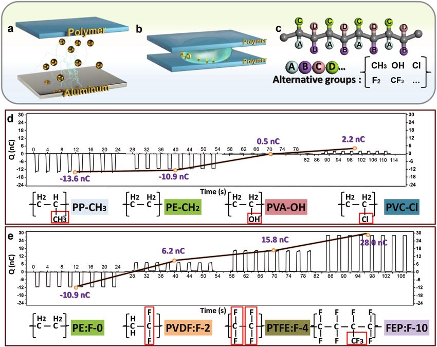
www.advancedsciencenews.com www.advmat.de which contains the CF3 group, exhibits the highest charge electrification ability. In the polymer–solid mode (Figure 1a), density. The CE effects in the polymer–polymer and polymer– a vertical contact-separation TENG is employed, and the tribo- liquid modes were similar. More importantly, the CE contribu- electric response of the polymers is indicated by the amount of tion of the unsaturated groups on the PTFE molecular chain charge transfer between the polymer and metal. In the polymer– was revealed for the first time. These unsaturated groups have a liquid mode (Figure 1b), a certain number of deionized water very strong EW ability, which is much stronger than that of the droplets is pressed between two polymer films, and the CE- common (CF2CF2) group on the main chain. The density induced charges on the water droplet are measured after sepa- of these unsaturated groups can be increased by sputtering a ration, as described in a previous work. Polymers with a carbon very thin film of PTFE on the original PTFE film surface. These main chain and different functional groups are selected, spe- studies illuminate the correlation between the molecular struc- cifically, a polypropylene (PP) film (methyl group), a poly(vinyl ture and macroscopic electrification behavior of materials. alcohol) (PVA) film (alcohol group), a poly(vinyl chloride) (PVC) The experimental system for studying the CE in the polymer– film (chlorine group), a polyethylene (PE) film (hydrogen group), solid and polymer–liquid modes is shown in Figure 1a,b. a PVDF film (bifluoride group), a PTFE film (tetrafluoro group), Polymers with similar main chains but different side-chain and an FEP film (trifluoromethyl group) (Figure 1c). The functional groups are used as solid materials, and the CE- thickness of these films is fixed at 50 µm, and the roughness induced charges on their surface are measured to determine the is ±50 nm, as shown in Figures S1 and S2 in the Supporting Figure 1. a) A vertical contact-separation TENG has been employed for the measurements and the contact area are all kept to be 40 mm × 40 mm. b) TENG for testing the polymer–liquid CE and the drop volume is 50 µL. c) Alternative polymer films have carbon as the main chain and A/B/C/D as the side chain. d) Polymer films of PP, PE, PVA, and PVC are contacted with Al foil to show their electrification ability. The electrode underneath polymer films are connected to the red wire of the electrometer; PE/PP films are positive and PVA/PVC films are negative. The amounts of transferred charges (Q) are recorded. e) The amount of Q between the F-containing polymers and Al, which are PE film-without F, PVDF film-bifluoro, PTFE film-tetrafluoro and FEP film-polyfluoro. PE film is positively charged and the other films are negatively charged. Adv. Mater. 2020, 2001307 2001307 (2 of 10) © 2020 WILEY-VCH Verlag GmbH & Co. KGaA, Weinheim
www.advancedsciencenews.com www.advmat.de Information. The effective contact area of the TENG in Figure 1 PVDF, PTFE, or FEP film; the measured charge transfer is 9.7, is 40 mm × 40 mm, and an aluminum foil is selected as the ref- 13.7, and 66.2 nC, respectively (Figure 2b–d). The output cur- erence tribomaterial in contact with the polymers. The scanning rent (Figure S4a—c, Supporting Information) reveals that the microscopy (SEM) image of the Al film in Figure S3 in the Sup- PE film is more positively charged during CE than the other porting Information shows that the Al surface is rather smooth, three films, indicating that its F groups give it a stronger EW with a roughness within ±25 nm. The surface roughness of the ability. The charge transfer results and the output current of Al film is low enough that the roughness has little effect on the TENGs consisting of PVDF–PTFE, PVDF–FEP, and PTFE– the CE; thus, the contributions of the functional groups are more FEP are shown in Figure S4d–f in the Supporting Information, apparent. In the polymer–solid mode, each polymer, which acts and the charge transfer in these three devices is 6.2, 63.4, and as one of the tribomaterials in a contact-separation TENG, is 41.1 nC, respectively. Interestingly, the EW ability of the poly- attached on top of a metal electrode, and the Al foil is attached mers increases with increasing density of the F groups on the to the other side. Both the metal electrode and the Al foil are side chain (Figure 2e–g). Thus, the FEP film, which contains connected to a Keithley 6514 electrometer. Figure 1d clearly the CF3 group, always captures more electrons during CE shows that the PP and PE films are positively charged after con- with the other polymers. The results of a similar experiment tacting the Al, and the charge transfer is −13.6 and −10.9 nC, using the other polymers (PP, PE, PVA, and PVC) are shown respectively. During CE, the PP and PE films tend to lose elec- in Figure S5 in the Supporting Information. The strength of trons when they are in contact with the Al. The methyl group the EW ability of each functional group follows the order has a greater ED ability than the hydrogen group; thus, the PP CH3 < H < OH < Cl < F. film appears to be more positive than the PE film. The PVA and On the other hand, the CE results obtained in the polymer– PVC films show negative charges, and the PVC film (2.2 nC) is liquid mode (Figures 1a and 2h–k) were also studied, and the more negative than the PVA film (0.5 nC) because the chlorine amount of tribo-induced charge on the water droplets is meas- group is a stronger EW group, which tends to attract more elec- ured using an electric meter.[22] The volume of the deionized trons than the alcohol group. When the main chain is the same, water is fixed at 50 µL. In this polymer–liquid mode, the deion- the different groups on the side chain determine the polarity of ized water is always positively charged, and the use of contact the polymer in CE. However, for polymers with the same main under pressure can maximize the contact area between the chain and side groups, the electrification can also be affected by droplet and polymer film, which in turn can maximize the CE the density of the side-chain groups. As shown in Figure 1e, as charges generated on the droplet.[22] PVA is soluble in water; the number of F groups on the side chain increases, the charge thus, no solid–liquid electrification tests were performed, and transfer also increases. During CE with Al, the charge transfer only the other six films were tested using this experimental amounts of the PE film (without F), PVDF film (bifluoride setup. Recent work has demonstrated that the CE between a group), PTFE film (tetrafluoride group), and FEP film (poly- fluoropolymer and an aqueous solution varies with the contact fluoride group) in the polymerization unit are −10.9, 6.2, 15.8, angle.[36] The average contact angles of water on the six films and 28.0 nC, respectively. Hence, the presence of strong EW are 98° for the PP film, 84° for the PVC film, 97° for the PE groups such as F groups on the side chain results in the gen- film, 97° for the PVDF film, 98° for the PTFE film, and 94° for eration of negative charges on the polymer surface during CE. the FEP film (Figure S6, Supporting Information). These con- Note that the roughness of the films may slightly affect the size tact angles are comparable, except for that of the PVC film. of the effective contact area, but we believe that this effect may The electrification ability of PVC in the polymer–liquid mode be very small, because these polymers have comparable surface (Figure 2h–k) is very low. To explain this phenomenon, we need roughness values (Figure S1, Supporting Information). We also to consider the ion adsorption effect. Positive ions (H+) may measured the microscale tribo-induced potential change on have adhered to the PVC surface during CE with water and lim- these polymers during CE with the metal probe using atomic ited the electron transfer. A similar phenomenon was observed force microscopy,[33,34] which may clarify the possible effect of in our previous study on a MgO surface,[23] where both elec- the surface roughness. The results were in good agreements trons and hydrogen ions were attracted to the surface of a MgO with the results from the TENGs. The glass transition tempera- film, and a neutralization effect was identified. Note that the tures of the polymers are −10 °C for the PP film, 20 °C for the PE and PP films appear to be positively charged when they are PVA film, 87 °C for the PVC film, −68 °C for the PE film, −35 °C in contact with Al, but they are negatively charged when they for the PVDF film, and −55 °C for the FEP film. Thus, these are in contact with water. When the contact area of the PP film materials are in a rubbery state at room temperature. In addi- and water increases from 0.5 to 4.0 cm2 (under pressure in the tion, the Young’s moduli of these materials are ≈1.5 ± 0.9 GPa, vertical direction), the CE charge changes from 0.5 to 0.6 nC except for that of the PVA film, which is 13 GPa, as shown (Figure 2h–k). The CE charges of the PE and PVDF films in Table S1. increase by 33% (0.6–0.8 nC) and 43% (0.7–1.0 nC), respectively. To further clarify the relationship between the functional The CE between a polymer and a liquid is believed to be domi- groups and the CE effect, four polymers with different F group nated by either hydroxide adsorption or electron transfer.[22,23] densities on the C chain (Figure S2d–g, Supporting Informa- The functional groups in the PE and PP films have been dem- tion) are brought into contact with each other, and the induced onstrated to have very weak EW ability, suggesting that it is dif- charge transfer is recorded (Figure 2a). The experimental ficult for them to capture electrons during contact with water setup for this test is based on a common contact-separation droplets. Thus, the adsorption effect of hydroxide ions could TENG with double dielectric layers.[35] A PE film connected to be the main reason for the negatively charged surface after CE. the red wire of the electrometer is placed in contact with the According to our previous study, the increase in contact area Adv. Mater. 2020, 2001307 2001307 (3 of 10) © 2020 WILEY-VCH Verlag GmbH & Co. KGaA, Weinheim

www.advancedsciencenews.com www.advmat.de
a b70 (1) 9.7 nC PE-PVDF c 70
(2) 13.7 nC PE-PTFE d 70
(3) 66.2 nC PE-FEP
PE (1)
PVDF 60
50
60
50
60
50
C2H4 C2H2F2
Q (nC)
40 40 40
Q (nC)
Q (nC)
30 30 30
20 20 20
10 10 10
0 0 0
0 4 8 12 0 4 8 12 0 4 8 12
Time (s) Time (s) Time (s)
(3) (4) e 70 f g
60 (4) 6.2 nC PVDF-PTFE 70
(5) 63.4 nC PVDF-FEP 70
(6) 41.1 nC PTFE-FEP
60 60
50
50 50
40
40 40
Q (nC)
Q (nC)
Q (nC)
30 30 30
20 20 20
C5F10 C4F4 10 10 10
(6)
FEP PTFE
0 0 0
0 4 8 12 0 4 8 12 0 4 8 12
Time (s) Time (s) Time (s)
h 5
i 5
j 5
k 5
2 2
Contact area is about 0.5 cm Contact area is about 1.0 cm Contact area is about 2.0 cm2 Contact area is about 4.0 cm2
4 4 4 4
Charge (nC)
Charge (nC)
Charge (nC)
Charge (nC)
3 3 3 3
2 2 2 2
1 1 1 1
0 0 0 0
PP PVC PE PVDF PTFE FEP PP PVC PE PVDF PTFE FEP PP PVC PE PVDF PTFE FEP PP PVC PE PVDF PTFE FEP
Materials Materials Materials Materials
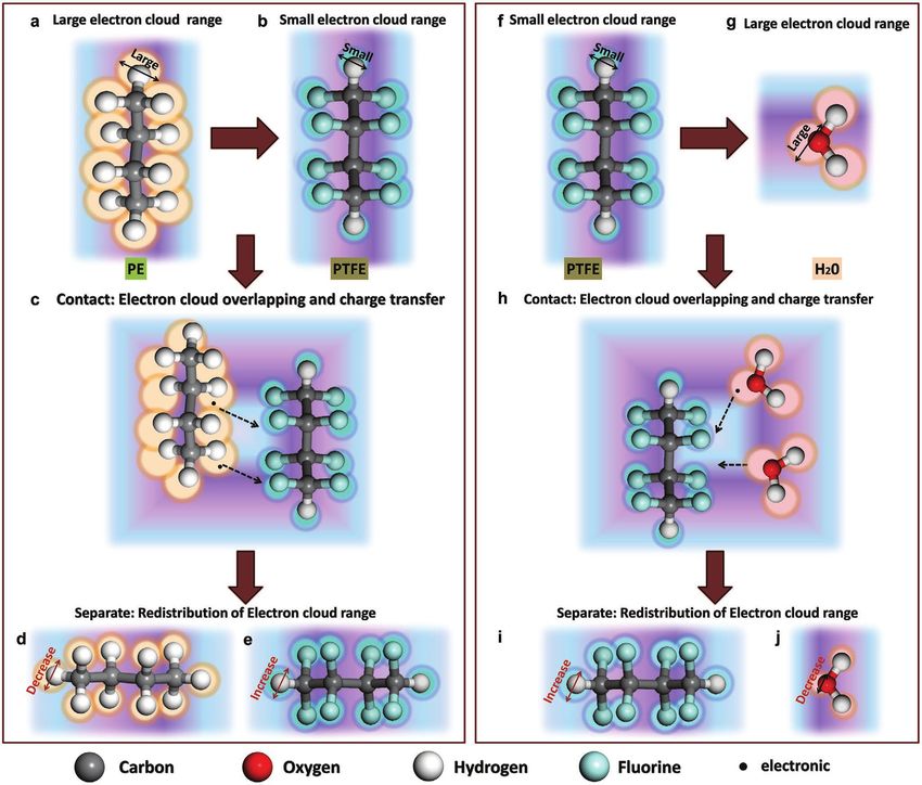
Figure 2. a) The schematic diagram of CE among the four selected polymer films in the polymer–polymer mode. PE film in line (1), (2), (3), PVDF
film in line (4), (5), and PTFE film in line (6) are connected to the red line of the electrometer. b) The charge transfer (Q) for PE-PVDF TENG device
and PE film is positive; c) The Q for PE-PTFE TENG device and PE film is positive; d) The Q for PE-FEP TENG device and PE film is positive; e) The Q
for PVDF-PTFE TENG device and PVDF film is positive; f) The Q for PVDF-FEP TENG device and PVDF film is positive; g) The Q for PTFE-FEP TENG
device and PTFE film is positive; the contact areas are all kept to be 40 mm × 40 mm. h–k) In the polymer–liquid mode, the Q for the four selected
films after contacting with the water: the maximum contact area is about: h) 0.5 cm2, i) 1.0 cm2, j) 2.0 cm2, k) 4.0 cm2; the volume of water is 50 µL.
Water is always positively charged.
results in a significant increase in the tribo-induced charge on conditions, the results for PP, PVC, and PE still have large
the droplet,[22] which is a typical result for the electron transfer error bars, as shown in Figure 2. By contrast, for PTFE and
model of CE. However, if the ion transfer effect dominates FEP, a very significant increase in tribo-induced charges with
the CE at a liquid–solid interface, increasing the contact area increasing contact area is observed. When the contact area
may not increase the tribo-induced charge. Many researchers increases from ≈0.5–4.0 cm2, the CE charge changes from 1.2
believe, on the basis of the ion adsorption model, that the to 3.2 nC for the PTFE film and from 2.1 to 4.3 nC for the FEP
concentration of hydroxide ions accumulated on the surface film, as shown in Figure 2k,h, respectively. Although the rate
of the water may exceed their bulk concentration,[37–39] which of increase for FEP (105%) is lower than that for PTFE (166%),
enhances the hydroxide adsorption during the CE at the liquid– the charge on the FEP surface is much larger than that on the
solid interface. In this case, the further pressing of the droplets PTFE surface. The smaller increase for FEP with increasing
between two polymer films (which squeezes the water from the contact area may be due to the effect of charge saturation on the
bulk to the surface) may increase the concentration of hydrogen droplet.[40] Hence, the strength of the EW ability of the mole
ions at the surface and thus suppress the preferential adsorp- cular chain can determine the electron transfer process during
tion of hydroxide ions. However, there is no effective method CE; this finding applies to CE in both the polymer–polymer and
of verifying whether ion adsorption actually dominates the polymer–liquid modes, because electron transfer is inevitable
CE between PE or PP and water droplets. The amount of ion during the interaction at the liquid–solid interface. When the
adsorption on these polymer surfaces is too low to be detected volume of the droplets is increased to 100 µL, the CE charge
by infrared spectroscopy, Raman spectroscopy, or nuclear mag- in the solid–liquid mode exhibits similar behavior (Figure S7,
netic resonance.[22] The experimental error during the measure- Supporting Information). The CE charge from a larger droplet
ment should be considered. The electrification performance of with the same contact area is almost the same as the results in
these polymers (PP, PVC, and PE) is very weak; thus, the con- Figure 2h–k, which indicates that the contact area rather than the
tribution of the interference parameters becomes notable. Even volume of the droplet is the key factor for CE. Scanning Kelvin
though we carefully reduced the effects of the experimental probe microscopy was also used to verify the homogeneity
Adv. Mater. 2020, 2001307 2001307 (4 of 10) © 2020 WILEY-VCH Verlag GmbH & Co. KGaA, Weinheimwww.advancedsciencenews.com www.advmat.de
a b c d
CH 2 CH 2O 821.06
CH2CHCl 1422.15
CH2 1501.53
O-H 3274.76
2.0 C
CHCl 1337.56
Transmittance (%)
Transmittance (%)
Transmittance (%)
CH 2 1414.32
F
CH2 2849.61
CHCl 1232.98
CH3 2959.64
CH2 2926.16
C-Cl 720.02
CH3 2910.01
1.5
Content ratio
1.0
CH3 1404.88
0.5
PP PVA PVC
0.0
C: 1 C:F 1:0.940 C:F 1:1.886 C:F 1:1.970 3400 2550 1700 850 3400 2550 1700 850 3400 2550 1700 850
-1 -1 -1
Wavenumber (cm ) Wavenumber (cm ) Wavenumber (cm )
e f
PE PVDF PTFE FEP
g h
C-F 1142.67 CF 982.46
CH2 2959.61
CH2 2896.34
C-C 1182.21
C-F 1202.63
CH2 1400.98
Transmittance (%)
Transmittance (%)
Transmittance (%)
Transmittance (%)
CF2 1199.31
CF2 1131.61
(CH2)n 728.52
CH2 1501.67
C-H 2959.64
C-H 3022.70
CF2 1274.86
3
PE PVDF PTFE FEP
3400 2550 1700 850 3400 2550 1700 850 3400 2550 1700 850 3400 2550 1700 850
-1 -1 -1 -1
Wavenumber (cm ) Wavenumber (cm ) Wavenumber (cm ) Wavenumber (cm )
Figure 3. a) The energy-dispersive X-ray spectroscopy (EDX) of C/F ratios of four films: the PE, PVDF, PTFE, FEP films. b–g) The structures of PP film
(b), PVA film (c), PVC film (d), PE film (e), PVDF film (f), PTFE film (g), and FEP film (h) are given by a Fourier transform infrared (ATR-FTIR) spectrum
and selected polymers are scanned from 4000 to 500 cm−1.
of the charge distribution at the microlevel, as shown in of the PVDF film is 2.98:1, which indicates that the CF bond
Figure S8a–c in the Supporting Information. Here, the differ- plays a dominant role in CE. Similarly, the proportion of CF2
ence in the electrical potential on the PTFE surface before and bonds in PTFE is larger (Figure S9f, Supporting Information),
after contact with the liquid was probed, although we could not and the area of CF3 bonds in FEP is the largest (Figure S9g,
observe any mosaic effect. A very small fluctuation of the poten- Supporting Information). Moreover, the CF2/CF3 ratios of PTFE
tial (≈0.2–0.3 V) on the surface is observed, which is within 10% and FEP are 7.68:1 and 1:2.40, respectively, indicating that CF2 is
of the total change in the potential. the main EW group in PTFE, and CF3 is the main EW group in
Selected polymers are analyzed by energy-dispersive X-ray FEP. The CF2 and CF3 functional groups both have strong EW
spectroscopy (EDX) and attenuated total reflectance Fourier ability, although that of CF3 is slightly stronger than that of CF2.
transform infrared (ATR-FTIR) spectroscopy, and the results are Thus, the FEP film can induce a stronger tribo-charge than the
summarized in Figure 3. As shown in Figure 3a, the C/F ratios PTFE film for a small contact area (Figure 2h). The PVDF film
of the PE and FEP films are 1:0 and 1:1.886, respectively, and the contains CF bonds, and it is unclear which functional groups
F content of the four fluorine-containing films increases gradu- are exposed to water on the film surface. Consequently, the
ally. This result can support the conclusion that the charge PVDF film exhibits poor electrification performance compared
transfer amount is affected by the presence of F. The ATR-FTIR with the PTFE and FEP films. The XPS results are consistent
spectra (Figure 3b–h) and XPS data (Figure S9, Supporting with the ATR-FTIR spectra, indicating that electron transfer
Information) together reveal the molecular structure. Each film during the CE in both the polymer–polymer and polymer–
clearly has characteristic peaks that reflect the positions of the liquid modes can be explained well in terms of the structure of
main chain structure and side-chain groups. According to the functional groups. In addition, for the CE in the polymer–
the XPS analysis (Figure S9a—c, Supporting Information), all liquid mode, if the functional groups do not have strong ED or
three films have a structure based on CO bonds, which is EW ability, electron transfer may be suppressed, and we may
due to the residue of the initiator used to fabricate the films. need to reconsider the contribution of the ion adsorption effect.
The residue may be present only in the chain-end structure but The electron transfer is the key element of CE with both
not in the polymerized units, in which case it cannot affect the polymer–polymer mode and polymer–liquid mode.[34] The core
structure of the polymer itself. Structural analysis reveals that concept of this electron transfer model is related to the motion
the presence of CH3 bonds in PP, OH bonds in PVA, and Cl of electrons outside atomic nuclei during the overlapping of
bonds in PVC is reflected in the triboelectric behavior of the the electron clouds. With the consideration of the EW ability
films. PP easily loses electrons, and PVC easily gains electrons. of functional group, we proposed a theoretical mechanism
The ATR-FTIR spectra show that the F content of the PE, PVDF, to explain the electron transfer principle between polymer–
PTFE, and FEP films increases gradually from none to F2/F3, polymer and between polymer–liquid, as shown in Figure 4. In
which proves that the main difference between these films is this simplified mechanism mode, the electron cloud indicates
the F content (Figure 3e–h). According to the XPS spectra, if we the chance of an electron appearing outside the nucleus. When
ignore the CC single bonds in the main chain (Figure S9d,e, the atomic nuclei have weak EW ability, the electron cloud can
Supporting Information), CH bonds occupy the largest area of occupy a large range. On the contrary, when atomic nuclei
the PE film, whereas large areas of the PVDF film are occupied have strong EW ability, the atom is covered with a small elec-
by CF bonds or CH bonds. In addition, the CF/CF2 ratio tron cloud. The shorter molecular chain is used to represent
Adv. Mater. 2020, 2001307 2001307 (5 of 10) © 2020 WILEY-VCH Verlag GmbH & Co. KGaA, Weinheimwww.advancedsciencenews.com www.advmat.de Figure 4. In the case of the main chain is same, the electron cloud range of different groups in the side chain is shown here. Polymer–polymer mode: a) PE film has high electron cloud range with light orange color. b) PTFE film has low electron cloud range with bright blue color. c) When the two films are in contact, their electron clouds partially overlap, and the electrons move from the PE film to the PTFE film. The two films are separated: d) the electron cloud of PE decreases; e) the electron cloud of PTFE increases. Polymer–liquid mode: f) PTFE film has small electron cloud range with bright blue color. g) H2O has large electron cloud range with light red color. h) During the contact, their electron clouds partially overlap, and electron transfer happens. When they are separated: i) the electron cloud of the H2O becomes smaller; j) the electron cloud of the PTFE becomes larger, the whole system reaches equilibrium. the molecular chain of the entire polymer in Figure 4. In the the two molecule to reach equilibrium. The separation of two polymer–polymer (PE and PTFE) mode (Figure 4a–e), the elec- materials allows the transferred charges to stay at one molecule tron cloud of H atom in PE film is expressed as a light orange and the CE effect can be achieved. Here, we assume that the (Figure 4a) and the electron cloud of F atom in PTFE film is transferred electron is shared by the electron cloud of the whole light yellow (Figure 4b). The environment for C in PE film and functional group after the separation and thus, the electron PTFE film are both sp[3] hybrids, so the dominating atoms for cloud distribution of the whole molecular section is changed electrification are related to H and F atoms. During the con- after electron transfer (Figure 4d,e). As for the polymer–liquid tact, the overlapping of electron cloud allows the electrons to mode (Figure 4f–j), the electron cloud of F atom in PTFE covers transfer from an atom with low electronegativity to an atom a small range (Figure 4f) and the electron cloud of O atom in with high electronegativity (the attraction force from the F water molecule occupies a larger range (Figure 4g). During nuclear is higher), as shown in Figure 4c. Then, the electron the CE process, as shown in Figure 4h, the electron clouds cloud range of PE molecule decreases and that of PTFE mole- partially overlap and the electrons in the water may transfer cule increases due to electron transfer (Figure 4d,e), prompting to PTFE film. The electron cloud of PTFE and water molecule Adv. Mater. 2020, 2001307 2001307 (6 of 10) © 2020 WILEY-VCH Verlag GmbH & Co. KGaA, Weinheim
www.advancedsciencenews.com www.advmat.de
reaches an equilibrium state due to electron transfer. Then, of unsaturated groups can be generated on the surface of the
the transferred charges stay at new positions after separation polymer film during the fabrication process. There have been
(Figure 4I,j). The bonding force between water molecules is a lot of researches analyzing molecular structure of fluorinated
just van der Waals force and thus, the charge recombination polymer, including both saturated and unsaturated groups
effect during the separation is more serious in comparison with at on the polymer chain.[41] However, the influences of these
polymer–polymer mode. The overlapping of the electron cloud unsaturated groups on the CE effect have not been consid-
between the twisted molecule chains is only a small probability ered. Taking PTFE as an example, the unsaturated groups
event. Moreover, if two overlapped electron clouds with com- with CC double bond can be generated either on the main
parable EW ability, the electron transfer cannot happen either. chain (CFCF) or at the end of the chain (–CFCF2). In
This can explain why there are only a small amount of charge this work, we have found that magnetron sputtering method
is generated during the CE with a large contact area. Hence, can be used to increase the unsaturated groups of the PTFE
by increasing the density of EW groups on the main chain of polymer. A new layer of PTFE film is sputtered on the original
polymer, we can increase the probability of electron transfer, PTFE film (treated PTFE) by magnetron sputtering (Figure 5a)
which can explain the high charge density obtained from PTFE and the unsaturated groups can be generated at two kinds of
and FEP films. positions, as can be seen in Figure 5b,c (main chain and end
In the above experiments, we only considered the saturated chain). The morphology of treated and common PTFE film
functional groups of the polymer molecular chain to the CE is shown in Figure S10a,d in the Supporting Information,
effect and the effect of unsaturated group on the CE should where the roughness of treated PTFE film is ±20 nm and that
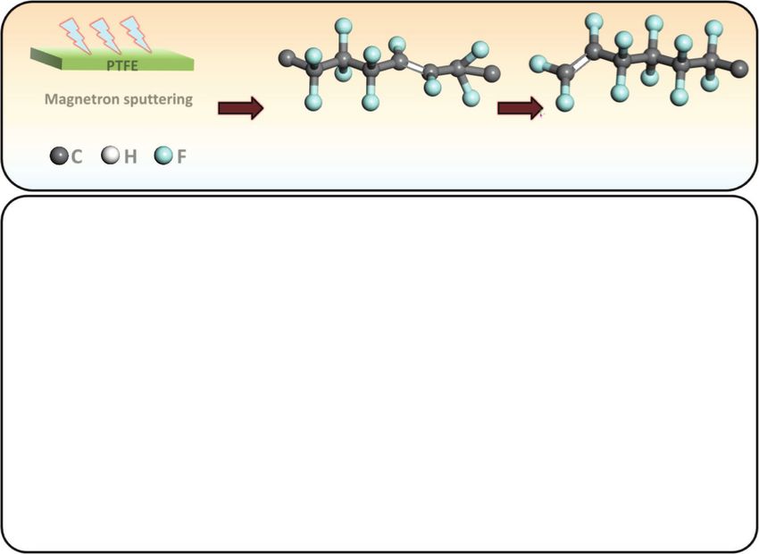
also be considered. It is important to note that a large number of untreated PTFE film is ±50 nm (Figure S10b,e, Supporting
a b c
PTFE
Magnetron spuering
F F F F F F F F F F F
— —
— —
— —
—
— —
— —
—
— —
— —
—
— —
C H F —C — C — C — C = C — C — C = C — C — C — C — C—
—
F F F F F F F F F
d0 e f 48
0 PTFE-FEP
-4 40 Treated PTFE-FEP
-4
-8 32
-12 -8
Q (nC)
Q (nC)
Q (nC)
24
-16
-12 16
-20
-16 8
-24 PTFE-PE PTFE-PVDF
-28 Treated PTFE-PE Treated PTFE-PVDF 0
-20
0 4 8 12 16 20 24 28 32 0 4 8 12 16 20 24 28 32 0 4 8 12 16 20 24 28 32
Time (s) Time (s) Time (s)
g5 2
h 2
i 2
Contact Area:≈0.5 cm 5 Contact Area ≈1.0 cm 5 Contact Area:≈2.0 cm
4 4 4
3 3 3
Q (nC)
Q (nC)
Q (nC)
2 2 2
1 1 1
PTFE-H2O PTFE-H2O PTFE-H2O
0 0 Treated PTFE-H2O 0 Treated PTFE-H20
Treated PTFE-H2O
0.0 0.5 1.0 1.5 2.0 0.0 0.5 1.0 1.5 2.0 2.5 0.0 0.5 1.0 1.5 2.0 2.5 3.0
Time (s) Time (s) Time (s)
Figure 5. a) Schematic of magnetron sputtered PTFE: the new PTFE is deposited on the original PTFE film by magnetron sputtering (treated PTFE
film). The thickness of deposition is about 200 nm. b) A kind of treated PTFE molecular mode with unsaturated groups marked in red boxes. c) Another
kind of treated PTFE molecular mode with unsaturated-end groups marked in red boxes. The charge transfer amount (Q) for the original PTFE and the
treated PTFE with: d) PE film, as the positive electrode; e) PVDF film, as the positive electrode; f) FEP film, as the negative electrode. The Q for the
original/treated PTFE with H2O in CE, and H2O as the positive electrode: g) the contact area is about 0.5 cm2; h) the contact area is about 1.0 cm2;
i) the contact area is about 2.0 cm2.
Adv. Mater. 2020, 2001307 2001307 (7 of 10) © 2020 WILEY-VCH Verlag GmbH & Co. KGaA, Weinheimwww.advancedsciencenews.com www.advmat.de Information). In addition, the C/F ratio measured by EDX stability and large quantities.[3,44–46] Hence, this sputtering data increase slightly from 1: 1.886 to 1: 1.969 (Figure S10c,f, method can be a facile and effective method to enhance the Supporting Information). As for the treated PTFE film, the performance of solid–liquid type TENG. We have also tried to contact angle with water is almost unchanged (Figure S10g,j, apply the similar magnetron sputtering treatment for another Supporting Information). The ATR-FTIR spectrum and XPS polymer (PE). The ATR-FTIR results of the PE film before and spectrum of the treated PTFE and original PTFE can be seen after sputtering treatment can be seen in Figure S15 in the in Figure S10h–l, respectively. In ATR-FTIR spectrum shown Supporting Information. The ATR-FTIR spectra of treated PE in Figure 5b,c, two new peaks can be observed at around film shows new peaks at positions of 959.81 and 771.41 cm−1 1670–1907 cm−1 for the treated PTFE film, which is related to (Figure S15a,b, Supporting Information),[43] which are related the unsaturated group on the main chain (1723.51 cm−1) and to the unsaturated groups on the molecular chain. The elec- at the end part (1850.11 cm−1).[42] The ATR-FTIR results in trification performance of sputtering treated PE is tested with Figure S10h,k in the Supporting Information also confirm that PP and PVDF in solid–solid mode (Figure S15c,d, Supporting the molecular structure of PTFE film before magnetron sput- Information). The output signal from PP-PE combination tering mainly has saturated groups, while no increase in the is enhance, while that from PE-PVDF combination is sup- peak signal of the saturated group at 1140.33 or 1201.85 cm−1 pressed. The results from solid–liquid mode of treated PE also can be observed after magnetron sputtering. The C atom in show slight enhancement (Figure S15e,f, Supporting Infor- the unsaturated group of PTFE molecular chain changes from mation). Hence, the EW ability of treated PE film is slightly sp[3] hybrid to sp[2] hybrid orbital. The greater proportion of enhanced by sputtering treatment. However, the change of s orbits in hybrid orbital (sp,[2] 1/3 and sp,[3] 1/4) leads to the the performance is not so significant in comparison with stronger ability to attract electrons, which means sp[2] hybrid that of PTFE, which is probably due to the weak EW ability of can provide a stronger EW ability. Accordingly, the existence hydrogen atom in PE. This result confirms that unsaturated of CC double bonds can enhance the EW ability of the whole groups of the polymer can be increased by the magnetron unsaturated functional group. The XPS results of the two films sputtering, while the performance of CE is highly dominated (Figure S10i,l, Supporting Information) show that the treated by the detailed EW ability of functional groups. PTFE molecule has much more CF2 bonds than CF3 bonds, In this work, we have studied the contribution of functional which means the CF3 on the side chain has been cleared. groups on polymer chain to the CE effect of both polymer– The treated PTFE surface has the a lot of CF bonds, suggesting polymer and polymer–liquid. The F group show the strongest the appearance of unsaturated groups on the molecular chain. EW ability in comparison with other materials and the The unsaturated groups can enhance the film’s electrification increase of the density of F groups on the main chain leads performance, which can be explained by the electron cloud to the increase of charge density, which decides that FEP film model. The existence of the CC double bond decreases with the CF3 group can offer the highest surface charge den- the electron cloud range of the whole unsaturated groups sity. The similar rules can also be applied for CE of polymer– and increases the possibility of electron cloud overlapping. liquid mode. The polymers with strong EW ability (PTFE and For the CE with polymer–polymer mode (the contact area is FEP) can generate significant electron transfer effect during 40 × 40 mm), the treated PTFE film with unsaturated groups the CE with liquids. Nevertheless, for the polymer with is significantly more negative than the original PTFE film. The quite weak EW ability (PP, PE and PVC), the induced charge charge transfer amounts of the combination of PE-(treated amounts are almost unchanged with the increase of contact PTFE) and PVDF-(treated PTFE) increase significantly in com- area, suggesting that the electron transfer effect is quite weak parison with that of original PTFE and the charge transfer and ion absorption effect may dominate the polymer–liquid amount of (treated PTFE)-FEP decreases (Figure 5d–f) (both CE of these polymers. PE/PVDF films act as the positive side and FEP film act as the More importantly, we have discovered that the unsaturated negative side). For the CE with polymer–liquid mode, when the groups (CFCF2 or CFCF) of PTFE have much stronger maximum contact area between treated PTFE film and water EW ability than the common CF2 group on the main chain, is about 0.5 cm2, the charge of CE is 1.9 nC, which is 72% since the CC bond in these unsaturated groups can enhance larger than the 1.1 nC of original PTFE film (Figure 5g). When the electronegativity of the whole functional group. The density the contact area is increased to be 1, 2, or 4 cm2 the amount of of these unsaturated groups can be deliberately increased by charge transfer between treated PTFE film and water is still sputtering a thin film of PTFE on the original surface of PTFE significantly larger than that of PTFE film (Figure 5h,i). Under film, indicating a facile and effective way to enhance the perfor- different contact areas with liquids, the transferred charges mance of a TENG device. In addition, the study of unsaturated of PTFE and treated PTFE film are shown in Figures S11 and groups may also offer some different explanations to other sur- S12 in the Supporting Information. The short-circuit current face modification methods of TENGs such as UV–ozone treat- and the matching resistance in the TENG device with PE/ ment, inductively coupled plasma etching, and so on. Based on treated-PTFE and PE/PTFE can be seen in Figure S13 in the the electron cloud of the atom and the molecular structure of the Supporting Information. The stability of the surface charges polymer, we proposed a theoretical mechanism to explain the on the treated-PTFE and PTFE film has also been studied electron transfer principle between polymer–polymer and (contact with PE), as can be seen in Figure S14 in the Sup- polymer–liquid. Hence, a better understanding of the CE on porting Information. Currently, PTFE is the most commonly both polymer–polymer and polymer–liquid interfaces can be used materials for polymer–liquid energy harvesting, which achieved with the consideration of both electron cloud overlap- is probably due to its low cost (cheaper than FEP), excellent ping and EW ability of functional groups. Adv. Mater. 2020, 2001307 2001307 (8 of 10) © 2020 WILEY-VCH Verlag GmbH & Co. KGaA, Weinheim
www.advancedsciencenews.com                                                                                                                www.advmat.de

Experimental Section                                                             [1] Z. L. Wang, A. C. Wang, Mater. Today 2019, 30, 34.
                                                                                [2] H. T. Baytekin, A. Z. Patashinski, M. Branicki, B. Baytekin, S. Soh,
   Materials: 7 polymer films, which included PP, PVA, PVC, PE, PVDF,                B. A. Grzybowski, Science 2011, 333, 308.
PTFE, FEP were available in the market without further modification.            [3] W. Xu, H. Zheng, Y. Liu, X. Zhou, C. Zhang, Y. Song, X. Deng,
Before the measurements, the polymer films were placed in a vacuum                   M. Leung, Z. Yang, R. X. Xu, Z. L. Wang, X. C. Zeng, Z. Wang,
drying oven, heated to 80 °C at 5 °C per minute, then held for an hour               Nature 2020, 578, 392.
for removing all the residual charges. Finally, it was naturally cooled         [4] R. Williams, J. Coll, Interface Sci. 1982, 88, 530.
to room temperature to obtain the prepared films. The water used in
                                                                                [5] Y. Sun, X. Huang, S. Soh, Angew. Chem. 2016, 55, 9956.
the experiment was deionized water to remove static electricity. For the
                                                                                [6] L. S. McCarty, G. M. Whitesides, Angew. Chem., Int. Ed. 2008, 47,
polymer–liquid measurements, the experimental details of polymer–
                                                                                     2188.
liquid measurements, including the parameters for squeezing motion
and so on, can be found in the references.[22] The purpose of using the         [7] J. Nie, Z. Wang, Z. Ren, S. Li, X. Chen, Z. L. Wang, Nat. Commun.
squeezing system was to maximize the contact area between droplet                    2019, 10, 2264.
and PTFE and to maximize the amount of transferred charge between               [8] Z. H. Lin, G. Zhu, Y. S. Zhou, Y. Yang, P. Bai, J. Chen, Z. L. Wang,
water and PTFE. Therefore, the contact time of the liquid with PTFE was              Angew. Chem., Int. Ed. 2013, 52, 5065.
within 2 s.                                                                     [9] T. J. Lewis, J. Phys. D: Appl. Phys. 1990, 23, 1469.
   Methods: The electrical signals of all materials were determined by        [10] L. Huang, S. Lin, Z. Xu, H. Zhou, J. Duan, B. Hu, J. Zhou, Adv.
a Keithley 6514 System Electrometer. The separation distance and the                 Mater. 2020, 32, 1902034.
motion frequency of TENG were unchanged during all the experiments             [11] H. Chang, G. Wang, A. Yang, X. Tao, X. Liu, Y. Shen, Z. A. Zheng,
due to a digital linear motor. Microscopic morphology of the material was            Adv. Funct. Mater. 2010, 20, 2893.
given using a scanning SU8020 cold-field scanning electron microscope         [12] K. Parida, G. Thangavel, G. Cai, X. Zhou, S. Park, J. Xiong, P. S. Lee,
(SEM), while the elemental analysis was given by energy-dispersive                   Nat. Commun. 2019, 10, 2158.
X-ray spectroscopy (EDX) of the SU8020 microscope. The structure               [13] Z. L. Wang, W. Wu, Angew. Chem., Int. Ed. 2012, 51, 11700.
of the material was given by a Fourier transform infrared (see FTIR,           [14] G. G. Touchard, T. W. Patzek, C. J. Radke, IEEE Trans. Ind. Appl.
VERTEX80v) spectrophotometer in attenuated total reflectance mode                    1996, 32, 1051.
(ATR) with the pristine and selected polymers was scanned from 4000 to        [15] L. E. Helseth, X. D. Guo, Langmuir 2015, 31, 3269.
500 cm−1. The X-ray photoelectron spectroscopy (XPS) investigation            [16] D. Choi, D. S. Kim, Langmuir 2014, 30, 6644.
was measured by a VG ESCALAB MKII spectrometer with an Mg Kα
                                                                               [17] D. Yoo, S.-C. Park, S. Lee, J.-Y. Sim, I. Song, D. Choi, H. Lim,
excitation (1253.6 eV). The roughness and the contact angle of the
                                                                                     D. S. Kim, Nano Energy 2019, 57, 424.
material were given by a step meter (KLA-TencorP7) and a contact angle
                                                                              [18] D. Choi, D. Yoo, K. J. Cha, M. La, D. S. Kim, Nano Energy 2017, 36,
measuring machine (CA100C), respectively. PTFE film with unsaturated
double bonds was prepared by a Denton magnetron sputtering coating                   250.
instrument (Discovery635).                                                    [19] C. Xu, A. C. Wang, H. Zou, Y. Dai X. He, P. Wang, Y. Wang, P. Feng,
                                                                                     D. Li, Z. L. Wang, Adv. Mater. 2018, 30, 1706790.
                                                                              [20] S. Lin, L. Xu, L. Zhu, X. Chen, Z. L. Wang, Adv. Mater. 2019, 31,
                                                                                     1901418.
Supporting Information                                                        [21] S. Lin, L. Xu, C. Xu, Z. L. Wang, Adv. Funct. Mater. 2020, 30,
                                                                                     1909724.
Supporting Information is available from the Wiley Online Library or          [22] J. Nie, Z. Ren, L. Xu, S. Lin, F. Zhan, X. Chen, Z. L. Wang, Adv.
from the author.                                                                     Mater. 2020, 32, 1905696.
                                                                              [23] S. Lin, L. Xu, A. C. Wang, Z. L. Wang, Nat. Commun. 2020, 11, 399.
                                                                              [24] P. K. Yang, L. Lin, F. Yi, X. Li. K. C. Pradel, Y. Zi, C. Wu, J. H. He,
                                                                                     Y. Zhang, Z. L. Wang, Adv. Mater. 2015, 27, 3817.
Acknowledgements                                                              [25] V. K. Thakur, G. Ding, J. Ma, P. S. Lee, X. Lu, Adv. Mater. 2012, 24,
S.L. and J.N. contributed equally to this work. This work was supported              4071.
by the National Key R&D Project from Minister of Science and                  [26] Y. Qian, J. Nie, X. Ma, Z. Ren, J. Tian, J. Chen, H. Shen, X. Chen,
Technology (2016YFA0202704), the National Natural Science Foundation                 Y. Li, Nano Energy 2019, 60, 493.
of China (Grant No. 51775049), Beijing Natural Science Foundation             [27] Y. Ding, Y. Shi, J. Nie, Z. Ren, S. Li, F. Wang, J. Tian, X. Chen,
(4192069), the Beijing Municipal Science & Technology Commission                     Z. L. Wang, Chem. Eng. J. 2020, 388, 124369.
(Z171100000317001), and Young Top-Notch Talents Program of Beijing            [28] X. Ma, S. Li, M. Iwamoto, S. Lin, L. Zheng, X. Chen, Nano Energy
Excellent Talents Funding (2017000021223ZK03).                                       2019, 66, 104090.
                                                                              [29] S. H. Shin, Y. H. Kwon, Y. H. Kim, J. Y. Jung, M. H. Lee, J. Nah, ACS
                                                                                     Nano 2015, 9, 4621.
                                                                              [30] J. W. Lee, H. J. Cho, J. S. Chun, K. N. Kim, S. Kim, C. W. Ahn,
Conflict of Interest                                                                 I. W. Kim, J.-Y. Kim, S.-W. Kim, C. Yang, J. M. Baik, Sci. Adv. 2017, 3,
                                                                                     1602902.
The authors declare no conflict of interest.
                                                                               [31] J. P. Lee, J. W. Lee, J. M. Baik, Micromachines 2018, 9, 532.
                                                                              [32] S. Li, Y. Fan, H. Chen, J. Nie, Y. Liang, X. Tao, J. Zhang, X. Chen,
                                                                                     E. Fu, Z. L. Wang, Energy Environ. Sci. 2020, 13, 896.
                                                                              [33] P. K. Yang, Z. H. Lin, K. C. Pradel, L. Lin, X. Li, X. Wen, H. J. He,
Keywords                                                                             Z. L. Wang, ACS Nano 2015, 9, 901.
molecular chains, polymer electrification, triboelectric nanogenerators,      [34] A. C. Wang, B. Zhang, C. Xu, H. Zou, Z. Lin, Z. L. Wang, Adv. Funct.
unsaturated function groups                                                          Mater. 2020, 1909384.
                                                                              [35] J. K. Moon, J. Jeong, D. Lee, H. K. Pak, Nat. Commun. 2013, 4, 1487.
                                               Received: February 25, 2020    [36] L. E. Helseth, Langmuir 2019, 35, 8268.
                                                     Revised: April 4, 2020   [37] R. Zimmermann, S. Dukhin, C. Werner, J. Phys. Chem. B 2001, 105,
                                                        Published online:            8544.

Adv. Mater. 2020, 2001307                                          2001307 (9 of 10)                 © 2020 WILEY-VCH Verlag GmbH & Co. KGaA, Weinheim
www.advancedsciencenews.com www.advmat.de
[38] J. K. Beattie, A. M. Djerdjev, Angew. Chem., Int. Ed. 2004, 43, [43] R. J. de Kock, P. A. H. M. Hol, Polym. Lett. 1964, 2, 339.
3568. [44] F. Yi, L. Lin, S. Niu, P. K. Yang, Z. Wang, J. Chen, Y. Zhou, Y. Zi,
[39] J. K. Beattie, A. M. Djerdjev, G. V. Franks, G. G. Warr, J. Phys. Chem. J. Wang, Q. Liao, Y. Zhang, Z. L. Wang, Adv. Funct. Mater. 2014, 24,
B 2005, 109, 15675. 7488.
[40] D. C. Taflin, T. L. Ward, E. J. Davis, Langmuir 1989, 5, 376. [45] M. Wang, J. Zhang, Y. Tang, J. Li, B. Zhang, E. Liang, Y. Mao,
[41] M. I. Bro, C. A. Sperati, J. Polym. Sci. 1959, 38, 289. X. Wang, ACS Nano 2018, 12, 6156.
[42] M. Pianca, E. Barchiesi, G. Esposto, S. Radice, J. Fluor. Chem. 1999, [46] J. H. Lee, S. M. Kim, T. Y. Kim, U. Khan, S. W. Kim, Nano Energy
95, 71. 2019, 58, 579.
Adv. Mater. 2020, 2001307 2001307 (10 of 10) © 2020 WILEY-VCH Verlag GmbH & Co. KGaA, WeinheimYou can also read