Pulsar 320 Strobe Controller - Operator's Manual & Installation Guide
←
→
Page content transcription
If your browser does not render page correctly, please read the page content below
Pulsar 320
Strobe Controller
  Operator’s Manual
  & Installation Guide

  Pulsar 320 Manual
1595.050051 REV-02 Manual, Operation, Pulsar 320

    The shipping container should contain the following items:

     Packing List

     Qty		             Description				                             Ai Part #

     1         Pulsar 320 Controller
     1         Installation CD
     2         3 Pin, Trigger input connectors		                   1805314
     1         2 Pin, Power input connector			                     1777989
     1         USB Cable					                                      172-1024

         (1)              (1)               (x2)           (1)             (1)

                    A d v a n c e d i l l u m i n a t i o n , I n c.
                               24 Peavine Dr
                          R o c h e s t e r VT 0 5 7 6 7
                                8 0 2 .7 6 7 .3 8 3 0
2                   a d v a n c e d i l l u m i n a t i o n .c o m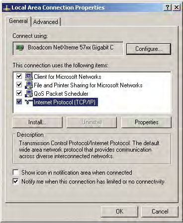
Pulsar 320 Controller
                                            Operator’s Manual

                                            Table of Contents

1.0 Introduction . . . . . . . . . . . . . . . . . . . . . . . . . . . . . . . . . . . . .       6
    1.1 Safety
    1.2 Warranty
    1.3 Return Policy
2.0 Features . . . . . . . . . . . . . . . . . . . . . . . . . . . . . . . . . . . . . . . . .   7
    2.1 Light Head Outputs
    2.2 User Interface
		 2.2.1 Remote Operation
		 2.2.2 Local Control
    2.3 Diagnostics
3.0 Quick Start . . . . . . . . . . . . . . . . . . . . . . . . . . . . . . . . . . . . .        8
    3.1 Pulsar 320 Controller Cable Connections
		 3.1.1 Power
		 3.1.2 Light Head
    3.2 Pulsar 320 Status Indicator Lights
		 3.2.1 Green
		 3.2.2 Amber
		 3.2.3 Red
    3.3 USB Control
4.0 Operation
    4.1 Definition of Terms . . . . . . . . . . . . . . . . . . . . . . . . . . . . .            12
		 4.1.1 Duty Cycle
		 4.1.2 Latency
		 4.1.3 Led and Light Head Characteristics
			 4.1.3.1                  LED forward voltage
			 4.1.3.2                  LED thermal resistance
			 4.1.3.3                  LED voltage slope
			 4.1.3.4                  Light head characteristics
		 4.1.4 Period
		 4.1.5 Pulse Width
		 4.1.6 Repetition Rate
		 4.1.7 Signatech II
		 4.1.8 Strobe modes
		 4.1.9 Trigger
		 4.1.10 Trigger Delay

                                  Pulsar 320 Manual                                                   3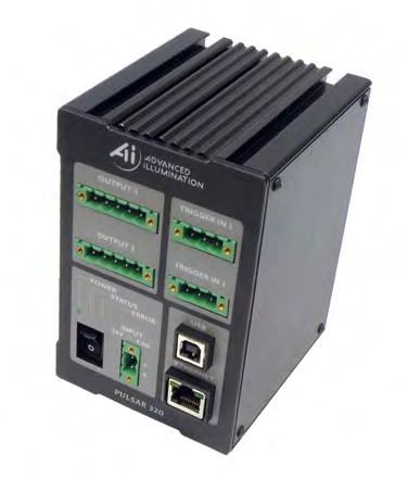
4.2 Pulsar 320 Controller Cable Connections
    		 4.2.1 Power
    		 4.2.2 Trigger
    		 4.2.3 Ethernet
    		 4.2.4 USB
    		 4.2.5 Light Head
    4.3 Pulsar 320 Status Indicator Lights
    		 4.3.1 Green
    		 4.3.2 Amber
    		 4.3.3 Red
        4.4 Host Computer Control (Remote)
    		 4.4.1 Software Installation
    		 4.4.2 Running Under Host Computer Control
                 4.4.2.1        Configure Pulsar 320
    			 4.4.2.2                 Launch Pulsar 320 Controller User Interface
    			 4.4.2.3                 Pulsar 320 Utility Dialog Box Status Indicators
    				 4.4.2.3.1                            Light Head
    				 4.4.2.3.2                            USB Connection
    				 4.4.2.3.3                            Status Panels
    			 4.4.2.4                 Pulsar 320 User Interface Output Controls
    				 4.4.2.4.1                            Select Channel
    				 4.4.2.4.2                            Program Button
    				 4.4.2.4.3                            Mode
    				 4.4.2.4.4                            Control Settings
    				 4.4.2.4.5                            Protection
    				 4.4.2.4.6                            Triggers
    				 4.4.2.4.7                            Test
        4.5 External Trigger Interface
            4.5.1 Alternate Trigger Configurations
    5.0 Custom Programming . . . . . . . . . . . . . . . . . . . . . . . . . . 25
    6.0 Troubleshooting . . . . . . . . . . . . . . . . . . . . . . . . . . . . . . . . . 25
        6.1 Pulsar 320 Status Indicator Lights
        6.2 Error Codes
    7.0 Specifications . . . . . . . . . . . . . . . . . . . . . . . . . . . . . . . . . . . 27
    8.0 Advanced Users Section . . . . . . . . . . . . . . . . . . . . . . . . 31
    9.0 Appendix . . . . . . . . . . . . . . . . . . . . . . . . . . . . . . . . . . . . . . . . 32
        A: Trigger Connection Diagram
        B: Pulsar 320 Loader Utility
        C: Installation Drawing
        D: TCP/IP Setup Instructions

4                     a d v a n c e d i l l u m i n a t i o n .c o m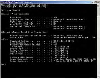
Pulsar 320 Figures & Tables
List of Figures

Figure 1:    Pulsar 320 front panel . . . . . . . . . . . . . . . . . . . . . . . . . . . . . . . . . . . . . . . . . . .                 9
Figure 2:    24V power supply connection . . . . . . . . . . . . . . . . . . . . . . . . . . . . . . . . . . .                            9
Figure 3:    Pulsar 320 Light head output connection . . . . . . . . . . . . . . . . . . . . . . . .                                     10
Figure 4:    Status indicator lights . . . . . . . . . . . . . . . . . . . . . . . . . . . . . . . . . . . . . . . . . . .               10
Figure 5:    USB dialog open . . . . . . . . . . . . . . . . . . . . . . . . . . . . . . . . . . . . . . . . . . . . . . . .             11
Figure 6:    USB Connected . . . . . . . . . . . . . . . . . . . . . . . . . . . . . . . . . . . . . . . . . . . . . . . .               11
Figure 7:    Ready to program test mode . . . . . . . . . . . . . . . . . . . . . . . . . . . . . . . . . . . .                          12
Figure 8:    USB Connection . . . . . . . . . . . . . . . . . . . . . . . . . . . . . . . . . . . . . . . . . . . . . . . .              16
Figure 9:    Light Head Connection Diagram . . . . . . . . . . . . . . . . . . . . . . . . . . . . . . . .                               17
Figure 10A: Software Installation Window . . . . . . . . . . . . . . . . . . . . . . . . . . . . . . . . . . .                           18
Figure 10B: Software Installation, Program Group . . . . . . . . . . . . . . . . . . . . . . . . . . .                                   18
Figure 11A: GUI Dialog Window . . . . . . . . . . . . . . . . . . . . . . . . . . . . . . . . . . . . . . . . . . . .                    19
Figure 11B: TCP/IP Dialog Window . . . . . . . . . . . . . . . . . . . . . . . . . . . . . . . . . . . . . . . . .                       20
Figure 11C: Settings Window . . . . . . . . . . . . . . . . . . . . . . . . . . . . . . . . . . . . . . . . . . . . . . . .              20
Figure 11D: Query Window . . . . . . . . . . . . . . . . . . . . . . . . . . . . . . . . . . . . . . . . . . . . . . . . .               20
Figure 12: Trigger Connector . . . . . . . . . . . . . . . . . . . . . . . . . . . . . . . . . . . . . . . . . . . . . . .               24
Figure 13: Trigger Pinout . . . . . . . . . . . . . . . . . . . . . . . . . . . . . . . . . . . . . . . . . . . . . . . . . . .          24
Figure 14: S1, SW2 & SW3 locations . . . . . . . . . . . . . . . . . . . . . . . . . . . . . . . . . . . . . . .                         31
Figure 15: Trigger Connection Diagram . . . . . . . . . . . . . . . . . . . . . . . . . . . . . . . . . . . .                            33
Figure 16: Cognex Connection Diagram . . . . . . . . . . . . . . . . . . . . . . . . . . . . . . . . . . . .                             34
Figure 17: IPD Connection Diagram - Typical Trigger Wiring . . . . . . . . . . . . . . . . .                                             34
Figure 18: IPD Connection Diagram - Vision Appliance, Relay/PLC Module . .                                                               35
Figure 19: Pulsar 320 Loading Utility . . . . . . . . . . . . . . . . . . . . . . . . . . . . . . . . . . . . . . . .                    36
Figure 20: Installation Drawings . . . . . . . . . . . . . . . . . . . . . . . . . . . . . . . . . . . . . . . . . . . .                 39
Figure 21:   Windows IP Configuration . . . . . . . . . . . . . . . . . . . . . . . . . . . . . . . . . . . . . . .                      40
Figure 22: Local Area Properties . . . . . . . . . . . . . . . . . . . . . . . . . . . . . . . . . . . . . . . . . . . .                 41
Figure 23: Internet Protocol Properties . . . . . . . . . . . . . . . . . . . . . . . . . . . . . . . . . . . . .                        41
Figure 24:   Windows IP Configuration . . . . . . . . . . . . . . . . . . . . . . . . . . . . . . . . . . . . . . .                      42
Figure 25:   USB Port Configuration . . . . . . . . . . . . . . . . . . . . . . . . . . . . . . . . . . . . . . . . .                    45
Figure 26: Pulsar TCP/IP Connection and IP Dialog Window . . . . . . . . . . . . . . . .                                                 46

List of Tables

Table 1: Light head output connector pin description . . . . . . . . . . . . . . . . . . . . . . . .                                     17
Table 2: Trigger connector pin description . . . . . . . . . . . . . . . . . . . . . . . . . . . . . . . . . . .                         24
Table 3:  Specifications . . . . . . . . . . . . . . . . . . . . . . . . . . . . . . . . . . . . . . . . . . . . . . . . . . . . . . .   26-29
Table 4: Internal switch functions . . . . . . . . . . . . . . . . . . . . . . . . . . . . . . . . . . . . . . . . . . . .               30

                                             Pulsar 320 Manual                                                                                5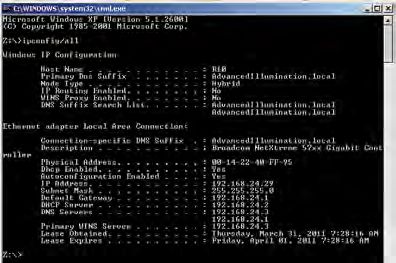
1.0 Introduction

The Pulsar 320 Controller, used in conjunction with an external 24VDC
power supply, is a compact, 2 output, high power pulse (strobe only) current
source incorporating a wide range of flexibility in selecting the operating
parameters. The unit may be controlled and operated locally (with optional
local control interface) or remotely via a USB interface and host computer.
In addition, the unit employs built in Ethernet connectivity.

The balance of this manual contains the necessary operating instructions,
specifications and other details required to allow the user to utilize the full
capabilities of the Pulsar 320.

1.1 Safety

The Pulsar 320 is designed to protect Advanced illumination light heads
having the Signatech I or Signatech II light head identification parameters.
When using light heads configured for Signatech I, an adapter cable must be
used to connect these lights to the Pulsar 320.

In certain modes of operation, the output voltages and currents provided by
the Pulsar 320 could result in a potentially injurious or fatal electrical shock.
For this reason, light heads should be connected BEFORE the
power switch is turned on. At no time should the operator touch the
output connector pins or light head leads when the power is on.

During normal operation, the Pulsar 320 may reach light head output
voltages as high as 100 volts. For specific applications, or to comply with
local codes, the Pulsar 320 may be configured to limit the light head output
voltage to a maximum of 48 volts. Please contact Advanced illumination
when this requirement exists.

Advanced illumination makes no warranty, expressed or implied, if
illumination or other devices produced by manufacturers other than
Advanced illumination are connected to the Pulsar 320.

1.2 Warranty

Every Advanced illumination, Inc. (Ai) product is thoroughly inspected and
tested before leaving the factory. Products are warranted to be free of
defects in workmanship and materials for a period of TWO YEARS from the

6                a d v a n c e d i l l u m i n a t i o n .c o m
original date of purchase. Should a defect develop during this period, return
the complete product, freight prepaid, to one of Ai’s distributors or to the
Ai factory. Ai will inspect the unit, and if a defect is found will, at our option,
repair or replace the product without charge. Ai disclaims liability for any
implied warranties, including implied warranties or “merchantability” and
“fitness for a specific purpose.”

Ai cannot be held responsible for the unauthorized or inappropriate use of
our products.

NO LIABILITY FOR CONSEQUENTIAL DAMAGES.

In no event shall Advanced illumination, Inc. be liable for consequential,
special, incidental or indirect damages of any kind arising from the sale or
use of products.

1.3 Return Policy

Standard Products may be returned within 30 days of receipt of the order.
Products must be in resalable condition, in function and appearance, with
shipping charges prepaid. A restocking fee of 15% will be applied to all
items accepted for return to stock. If you need to make a return, please
call our Customer Service Department at 802.767.3830 x237 for a Return
Merchandise Authorization (RMA) number.  Clearly mark the outside of
the package with the RMA number.

NO RETURNS CAN BE ACCEPTED FOR STANDARD
VARIATION, CUSTOM VARIATION, AND CUSTOM
PRODUCTS.

There are currently over 100,000 unique configurations of the Ai product
line.  Therefore, we cannot restock a light built to your specifications.  We
would be glad to help you order your light if you are unsure of the correct
part number or your exact requirements.

                         Pulsar 320 Manual                                        7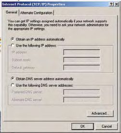
2.0 Features

The following is a brief overview of the features provided by the Pulsar 320.
These features will be covered in greater detail within the Operation and
Specification sections of the manual.

2.1 Light Head Outputs

Two outputs capable of high power are provided. Each will provide up to
50A of pulse current drive. The current of each channel is independently
selectable. Output pulse widths can be set between 1 and 100 milliseconds
in 1 microsecond increments at pulse repetition rates up to 400 Hz.

2.2 User Interface

2.2.1 Remote Operation: Remote operation via a host computer
allows the operator to make full use of the flexibility offered by the Pulsar
320. Communication is accomplished by both a USB interface and Ethernet.
Operating parameters are set by user friendly Windows based Pulsar 320
controller software. Supported operating systems are Windows 2000,
Windows XP, and Windows Vista.

2.2.2 Local Control (future implementation): An optional local control
is available which allows complete control of all Pulsar 320 settings and
features. A 2X16 LCD display along with four front panel momentary
switches allows users to easily navigate the Pulsar 320’s many features and
set points.

2.3 Diagnostics

A comprehensive set of diagnostic routines and indicators are provided.
Error codes are displayed by the Pulsar 320 via LED indicators on the front
panel.  Code definitions are found in section 6.0 “Troubleshooting” where
diagnostics are covered in greater detail.

3.0 Quick Start

The purpose of this section is to allow the operator to perform a quick
functional test. This will permit an easy checkout of the Pulsar 320 and
attached light head for proper operation.

8               a d v a n c e d i l l u m i n a t i o n .c o m
3.1 Pulsar 320 Controller Cable Connections:

                                    Two physical cable connections will be
                                    required to operate the Pulsar 320 and
                                    light head in self test mode. Figure 1
                                    shows the front panel of the Pulsar 320.

                                    3.1.1 Power: The Pulsar 320 requires
                                    an external 24 volt supply for operation.
                                    A power cable is provided. The black
                                    wire is negative and the red wire is
                                    positive. Plug the 2 pin connector
                                    into the socket labeled “VDC INPUT”.
                                    Observe the polarity markings on the
                                    panel below the VDC INPUT socket.
Figure 2: 24v Supply Connection     Refer to section 4.2.1 for more details
                                    regarding the 24 volt supply.

3.1.2 Light Head: Figure 3 shows how the output connectors on the
front panel of the Pulsar 320 mates with the light head connectors. Plug the

                         Pulsar 320 Manual                                      9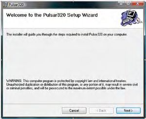
connector(s) from the light head(s)
                                          into the 5 pin socket in the front of
                                          the Pulsar 320 as shown in Figure 3.

                                          3.2 Pulsar 320 Status Indicator
                                          Lights:

                                          The Pulsar 320 has three LED
                                          indicator lights as shown in Figure 4
Figure 3: Pulsar 320 Light Head
Output Connection                     3.2.1 Green: This light indicates
that the Pulsar 320 has power either from the USB connection to the host
computer or the main 24VDC power connection.

3.2.2 Amber: The amber light indicates
the operational status of the Pulsar 320.
A blink rate of once per second indicates
normal operation. A blink rate of 5 times
per second indicates an error condition.

3.2.3 Red: The red light blinks an error
code in the case of an error condition.
The condition is indicated by three sets of
sequential flashes.  For example:  4 flashes
followed by 2 flashes followed by 3 flashes   Figure 4: Status Indicator Lights
indicate an error code of 423 which signifies
that the main power switch is off. Two common error codes are:

•    351: No light head detected.
•    423: The main power switch is off.

Refer to section 6.0 “Troubleshooting” for more detailed error code
information.

3.3 USB Control

  1. Connect Pulsar 320 USB cable to host PC, 24vDC, and
		 applicable light head
  2. Switch the main rocker power switch ON. A green power
     LED wil illuminate, followed by a flashing amber LED.

10               a d v a n c e d i l l u m i n a t i o n .c o m
3. Launch Pulsar 320 Utility
4. Choose USB
5. Select a USB port. Use port 0 by default. Press Connect
Figure 5: USB Dialog Open
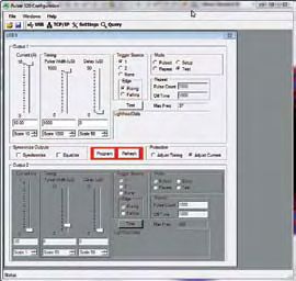
6. Upon Connecting to a USB port, the strobe settings
window will open (Fig 6) - Grayed-out outputs mean
no light is connected.
Figure 6: USB Connected
7. Test the light head: Press SETUP radio button.
a. The light head should immediately enter a continuous current
mode that will allow for visible detection that the light is
working. This mode is useful for orientating the light in the
system.
b. This mode should NOT be used for inspection purposes as it
will provide indeterminate results.
c. This mode may make the light appear to flicker - this is normal.
Pulsar 320 Manual 11Figure 7: Ready to Program Test Mode 8. Test the light in TEST MODE a. Press TEST radio button b. Set Pulse Width slider to 1000 c. Set current to 10 d. Press PROGRAM The light should flash at 10Hz with no external trigger applied. At this point the attached light head(s) will be ON. Any further adjustments can be made at any time using the same procedure as above. Adjusting PW will change the duration of the output pulse, and adjusting CURRENT will change the output level of the output pulse. Keep in mind that TEST mode always produces a 10Hz repetition rate pulse. The Pulsar 320 can communicate via ETHERNET. For instructions on this, please refer to the TCP/IP setup guide in Appendix D. 4.0 Operation The following section details the procedures for operation of the Pulsar 320 Controller and defines its various operating modes. 4.1 Definition of Terms The following terms are used within this manual and, more generally, in relation to machine vision illumination. 12 a d v a n c e d i l l u m i n a t i o n .c o m
4.1.1 Duty Cycle: The ratio of the time the light head is “on” (pulse
width, Pw) to the time it is “off” (period, Tp). Calculated as (Pw / Tp) x 100.
The result is expressed in percent. The Signatech II feature of the Pulsar
320 allows the Pulsar 320 to limit the maximum duty cycle based on the
characteristics of the driven light head.

4.1.2 Latency: The time between the receipt of a trigger signal and
initiation of the output drive pulse. The latency is the sum of the rise-times
and propagation delays within the trigger processing circuitry. This time is
purposely kept to a minimum.

4.1.3 LED and Light head Characteristics: Many factors contribute
to the operational parameters of an LED light head.  To optimize Pulsar
320/light head operation, these characteristics are stored as part of the
information provided to the Pulsar 320 by the Signatech II circuit within
the light head. Some of the variables that affect how the light head can be
driven are outlined below.

4.1.3.1 LED Forward Voltage: The forward voltage drop across an LED
(VFWD) depends upon the nature of the semiconductor junction and the
current through the LED.  The specified VFWD for an LED is usually given
at its recommended operating current. Please note that when driven by
high current pulses,VFWD can increase by 10 to 20 times. For this reason
voltage levels at the Pulsar 320 output can be as high as 100 volts.

4.1.3.2 LED Thermal Resistance: A measure of temperature difference
between the LED junction and the LED connection to an external heat sink.
Overheating of the junction is the primary cause of failure in LEDs. The
value of the LED thermal resistance, combined with the heat sink thermal
resistance and the overall thermal time constant determine the maximum
pulse width, pulse current, and duty cycle of the light head.

4.1.3.3 LED Voltage Slope: The relationship between VFWD and the
forward current IFWD, used by Signatech II to calculate the voltage required
to provide the desired current.

4.1.3.4 Light head Characteristics: Also contained within the data
provided by Signatech II to the Pulsar 320 are the number and type of LEDs
in each string and the number of parallel strings connected to each channel.

                        Pulsar 320 Manual                                     13
4.1.4 Period: The length of time between two successive pulses or the reciprocal of the pulse frequency. 4.1.5 Pulse Width: The length of time the light head is activated by the Pulsar 320. This is typically measured between the 50% amplitude points of the pulse. 4.1.6 Repetition Rate: The rate at which successive pulses are initiated. Also known as frequency, which is measured in Hertz (cycles per second). Repetition rate is usually multiple times per second. 4.1.7 Signatech II: A proprietary feature of Ai light heads and the Pulsar 320. Signatech identifies the type of light head connected to the Pulsar 320 and maintains safe operating limits for each type. The Pulsar 320 can be set so that Signatech preferentially limits pulse current, pulse width, or period to remain within the safe power dissipation range of the light head. 4.1.8 Strobe Modes: The strobe mode is used to “freeze” a moving item at a particular moment in time. Typically, with LED illumination sources, the strobe mode involves driving the light head with a high current, short duration pulse. This provides a very intense light output pulse. As long as the duty cycle is kept short, no damage to the LEDs occur as a result of the high current. 4.1.9 Trigger: The signal which initiates an output from the Pulsar 320 to the light head. The trigger signal is normally generated by an external source such as a camera or other sensor. Several modes of trigger operation are provided for in the Pulsar 320. The trigger may start on either a rising or falling edge. For test purposes, the Pulsar 320 also has an internal trigger source. 4.1.10 Trigger Delay: Certain applications require that a known, fixed time elapse between the receipt of a trigger signal and the initiation of an output pulse. This is the trigger delay. For example, if the trigger signal is received from a position sensor, prior to the arrival of the item to be inspected, a delay to account for that transit time would be introduced. If the trigger signal originates from the camera at the start of the shutter opening, a short delay might be introduced to assure the shutter is fully open or that the illumination pulse occurs elsewhere within the frame time. 14 a d v a n c e d i l l u m i n a t i o n .c o m
4.2 Pulsar 320 Controller Cable Connections

Four physical connections, one of which needs to be a USB or Ethernet will
be required to operate the Pulsar 320 and light head.  Refer back to figure 1
for an illustration of the Pulsar 320’s front panel.

4.2.1 Power: The input power connector is located near the bottom
center of the Pulsar 320’s front panel.  The Pulsar 320 requires an external
24 volt supply for operation.  The power supply needs to have sufficient
amperage rating to drive the light head in the desired mode of operation.
Advanced illumination recommends a minimum of 4A for full output
operation. A power cable is provided. The black wire is negative and the red
wire is positive. Plug the 2 pin connector into the socket labeled “INPUT”.
Observe the polarity markings on the right hand side of the connector
socket.

4.2.2 Trigger: The trigger input connectors are located at the upper right
of the Pulsar 320’s front panel. The differential trigger levels are CMOS/TTL
compatible but will accept input pulses as great as 30 V. Two input trigger
connectors are provided, one for each output. One trigger may be mapped
to both outputs. For more detailed triggering information refer to section
4.6 “External Trigger Interface”.

4.2.3 Ethernet: An RJ45 connector is located to the lower right of the
front panel and is provided for Ethernet connectivity. Standard protocols
supported are TCP/IP, UDP, TFTP via 10/100Base-T. For more detailed
information on Ethernet connectivity.

4.2.4 USB: The USB connector is located to the right and center of the
front panel. A host computer will communicate with the Pulsar 320 via
this USB connection. Connect the provided USB cable between the USB
connection on the host computer and the connector labeled USB on the
Pulsar 320. The Pulsar 320 is Microsoft HID USB compliant. Therefore, a
host computer with Windows 2000, Windows XP or Windows Vista will
auto-detect the Pulsar 320.

Figure 6 is a connection diagram for the output connector. Connect light
head(s) in accordance with Figure 6.

4.2.5 Light Head: Power to light heads is supplied by two independent
connectors on the front panel each having 5 pins. Table 1 identifies the

                       Pulsar 320 Manual                                    15
function of each pin for the 5 Pin power connector. Plug the connector
from each light head into the 5 pin socket as shown in Figure 3.
4.3 Pulsar 320 Status Indicator Lights
The Pulsar 320 has three LED indicator lights. Refer back to figure 4 for an
illustration of these indicator lights.
4.3.1 Green: This light indicates that the Pulsar 320 has power either
from the USB connection to the host computer or the main 24VDC power
connection.
4.3.2 Amber: The amber light indicates the operational status of the
Pulsar 320. A blink rate of once per second indicates normal operation. A
blink rate of 5 times per second indicates an error condition.
4.3.3 Red: The red light blinks an error code in the case of an error
condition. The condition is indicated by three sets of sequential flashes. For
example: 4 flashes followed by 2 flashes followed by 3 flashes indicates an
error code of 423 which signifies that the main power switch is off. Two
common error codes are:
• 351: No light head detected.
• 423: The main power switch is off.
Refer to section 6.0 “Troubleshooting” for more detailed error code
information.
4.4 Host Computer Control (REMOTE)
To take full advantage of the flexibility of
the Pulsar 320, software is provided which
permits the operating parameters to be set
by a host computer. The host computer
will be connected to the Pulsar 320 via a
USB port utilizing a USB Type B connector.
(See Figure 7) The USB port is Microsoft
HID compliant.
Figure 8: USB Connection
16 a d v a n c e d i l l u m i n a t i o n .c o mFigure 9: Light Head Connection Diagram
Table 1: Pin Function Chart
Pulsar 320 Manual 174.4.1 Software Installation: Pulsar 320 Controller user interface
software is required to set the operational parameters of the Pulsar 320.
This utility program is included on a CD and is installed as follows:
Note: Administrator Access to the system is usually required to install the
software.
Note: Supported operating systems are Windows 2000, Windows XP, and
Figure 10A: Software Installation Window
Windows Vista.
1. Insert Installation CD. If “Autoplay” is disabled, double click on “My
Computer” and open the CD drive.
2. Select Figure 10B: Software Installation, Program Group setup.exe.
18 a d v a n c e d i l l u m i n a t i o n .c o m3. Close all open applications if prompted and press OK.
4. Select a Program Group or use the default (Advanced Illumination) and
click Next. (See figure 10B.)
Note: If for some reason the automatic installation program cannot be used,
the software can be manually installed as follows: Place the four support files
from the CD in the same folder on the PC.
1) MPDH8USB_TCP.dll
2) PulsarAPI.dll
3) Pulsar320Loader.exe
4.4.2 Running under Host Computer Control
4.4.2.1 Configure Pulsar 320: The Pulsar 320 comes pre-configured
for normal use. See section 8 “Advanced User Section” for a complete
description of optional configurations.
4.4.2.2 Launch Pulsar 320 Controller user interface: To run the
program; go to Start -> Programs -> Advanced illumination -> Pulsar
Controller. Upon execution of the Pulsar Controller Utility program, the
dialog box shown in figure 11A will appear.
GUI Dialog Descriptions
Figure 11A: GUI Dialog Window
A. Open Dialog: Opens saved configuration
B. Save Dialog: Saves active configuration to host PC
C. USB: Opens USB connection dialog
Pulsar 320 Manual 19IPDialog Settings
Slew Rate
Address
Channel 1 High
High
Channel 2 High
Subnet
High Differential Trigger
Trigger 1
Gateway
Trigger 2
High
Advanced Settings
OK Cancel Limit Output to 48V
Figure 11B: TCP/IP Dialog Window
Set Close
Figure 11C: Settings Window
D. TCP/IP: Opens TCP/IP connection dialog
E. Settings: Opens Pulsar 320 configuration settings dialog
1. Slew Rate: used to reduce output ripple/ringing on the output
light pulse. Using the proper slew rate setting may improve
lighting performance.
a. High: (default) Used when pulsing below 100uSec
b. Mid-High: Used when pulsing 100 - 500uSec
c. Mid-Low: Used when pulsing 500 - 1000uSec
d. Low: Used when pulsing >1000uSec
2. Differential Trigger: Default checked. Activates the differential trigger
inputs. Recommendation is to leave this on unless otherwise
instructed.
Query
3. Advanced Settings: 48V output limit.
Device
Default unchecked. Apply this setting HW Version 7200-000186-110
to clamp the output strobe voltage to FW Version 8200-000219-113
48V. This may reduce performance Serial Number 0000000235
significantly for certain light sources.
Network
IP Address 192.168.24.99
F. Query: Displays device information Subnet Mask 255.255.255.0
Gateway 192.168.24.1
MAC Address DA:8E:00:00:00:33
Edit Network button allows for TCP/IP and
network configuration to occur for the device. Edit Network OK
Figure 11D: Query Window
20 a d v a n c e d i l l u m i n a t i o n .c o m4.4.2.3 Pulsar 320 Utility Dialog Box Status Indicators:
4.4.2.3.1 Light head: Window will appear active (not grayed-out) to indicate
there is a light head connected to the Pulsar320. The type of light head will also
be displayed when available.
4.4.2.3.2 USB Connection: If the menu is not grayed-out, it indicates that a
USB connection has been established between the host computer and the Pulsar
320. A USB connection is required to set up the Pulsar 320.
4.4.2.3.3 Status Panels: The two panels below the indicators show
connection status details. The top panel shows the results of the last command.
The bottom panel shows information about the Pulsar 320.
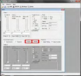
4.4.2.4 Pulsar 320 User Interface Output Controls:
4.4.2.4.1 Select Channel: The buttons labeled 1& 2 select which channel the
settings are to apply to. Synchronize and Equalize options can be selected by
checking the appropriate box.
• Synchronize: When this box is checked, any change in the settings for
the selected channel are added to the other unselected channel.
• Equalize: When this box is checked the settings of the selected channel
are applied directly to the remaining unselected channel.
4.4.2.4.2 Program Button: None of the settings described below will take
effect until the Pulsar 320 is programmed. Pressing the program button will
transfer the settings from the host computer to the Pulsar 320 allowing the
settings to take effect. The program button will be highlighted to indicate that
there are new settings that have not yet been transferred to the Pulsar 320.
4.4.2.4.3 Mode: One of four modes can be selected here.
• Pulsed: The Pulsar 320 produces pulses in response to a trigger signal.
The current and timing are determined by the control settings.
• Repeat (Pulse Train): The Pulsar 320 generates a succession of output
pulses for every single trigger event. Output then ceases until next
trigger event occurs. The number of pulses (pulse count) and the off
time (time between pulses) is entered in the appropriate text boxes
within the user control interface.
• Test: The Pulsar 320 outputs pulses at 10 hertz. The current and timing
are determined by the control settings.
Pulsar 320 Manual 21• Setup: The light head should immediately enter a continuous current
mode that will allow for visible detection that the light is working. This
mode is useful for orientating the light in the system.
4.4.2.4.4 Control Settings: There are three parameters that can be set to
control the output of the Pulsar 320.
• Current: The current setting determines the brightness of the light
output. Units are in Amps.
• Pulse Width: This is the length of the output pulse in microseconds.
• Delay: This is the time in microseconds, between detection of a trigger
signal and the start of the output pulse. Each parameter can be set by
adjusting its slider control or by entering the value directly in the text
box. Each slider control has a scale adjustment.
All settings are internally checked by the Pulsar 320 for compatibility with
the attached light head. Settings that will overdrive the light head will not be
allowed. If an unsafe setting is attempted, either the current or the pulse width
will automatically be reduced to a safe level and a message will be displayed
in the status box. The protection setting determines whether pulse width or
current is adjusted.
4.4.2.4.5 Protection: This selection determines what setting, timing or
current, is adjusted to produce a safe setting for the light head.
• Adjust Timing: Pulse width is reduced and current setting will be
maintained, so that the light head is not over driven.
• Adjust Current: Current is reduced and pulse width setting will be
maintained, so that the light head is not over driven.
Note: In some cases current may be adjusted when Adjust Timing is selected.
This happens when the current setting exceeds the absolute maximum current
setting for the light head. In this case current would be reduced to the absolute
maximum current and then timing adjusted as necessary.
4.4.2.4.6 Triggers: This selection determines which trigger input drives the
selected channel in Pulse, Timing Bypass, and Repeat modes. Use the edge
selection to choose the rising or falling edge.
4.4.2.4.7 Test: This selection provides a ‘One Shot’ trigger pulse to test
trigger settings and light head output.
22 a d v a n c e d i l l u m i n a t i o n .c o m4.5 External Trigger Interface
The Pulsar 320 employs two independent trigger inputs utilizing RS485 receivers.
These differential trigger inputs are effective in suppressing excessive noise and
EMI that could be present in the installation area or when long trigger lines
are required. Advanced illumination recommends using shielded, twisted pair
cable for the trigger inputs. Table 2 identifies the “standard” function of each pin
within the two external trigger interface connectors on the front panel of the
Pulsar 320 as shipped from the factory.
The wiring of the trigger input is dependent upon the trigger source. Though
the Pulsar 320 utilizes differential trigger inputs, single ended sources may also
be utilized.
Refer to Appendix “A” Figure 15 for common trigger connection schematics.
When utilizing a single ended trigger source it is important to realize that the
Pulsar 320 requires a “sourcing” output (PNP or Pull Up) as the trigger input is
“sinking”.
Figure 15 in appendix “A” is a connection diagram for the Trigger Input
connector. Suggested wiring conventions are shown depicting the most
common types of trigger sources. After setting the power switch to the “OFF”
position, connect an external trigger in accordance with this diagram.
For special trigger requirements not shown please contact Advanced
Illumination.
Trigger selection is performed using a host computer and the Pulsar 320
software.
In the single-ended trigger configuration, the input will accept TTL/CMOS
compatible signals and is internally clamped so that trigger inputs of up to 30 V
may be applied. If the differential trigger connection is chosen, the Pulsar 320
will recognize input logic levels that are compliant with RS232/485 protocol.
For all triggered modes, the trigger signal should have a minimum width of 2
microseconds and a rise and fall time of less than 200 nanoseconds.
Pulsar 320 Manual 234.5.1 Alternate Trigger Configurations:
Note: If the Pulsar 320 will be triggered by
a PLC refer to Appendix “A” for schematics
depicting different PLC configurations.
5.0 Custom Programming
For those needing to develop a custom
interface to control the Pulsar 320, please
consult Technical Support at Advanced
illumination.
Figure 12: Trigger Connector
Trigger Connector
Pin Function
Pin Number
1 Sig +
2 Sig -
Figure 13: Trigger Pinout
3 Common (GND)
Table 2: Pulsar 320 Trigger Connector
Pin Description
6.0 Troubleshooting
6.1 Pulsar 320 Status Indicator Lights
There are three LED indicators on the front panel of the Pulsar 320. During
normal operation, the green LED will be illuminated indicating that power is
“on.” Just to the right of the green LED, an amber LED will pulse at about
1 pulse per second. This “heartbeat” indication occurs when the operating
conditions are normal. If a fault is sensed, the amber LED will start to flash
rapidly, about 5 times per second, and the red LED just to the right will produce
a sequence of flashes to form an error code. Count the flashes and refer to the
error codes listed below.
Please note that there are several hundred error codes. Most of these are for
factory use in diagnosing problems which occur during initial test and calibration
24 a d v a n c e d i l l u m i n a t i o n .c o mprocedures. Only the codes most commonly encountered in use are listed
here, together with a few which would indicate an internal fault. If a code is
encountered which is not listed here, the operator should contact Technical
Support at Advanced illumination for further assistance. If the corrective action
suggested for the listed error code does not resolve the problem, the operator
should contact Advanced illumination.
6.2 Error Codes
The codes are listed below in bold face with a description of the fault indicated
and a corrective action.
351 No lighthead detected.
Corrective action – Be sure lighthead is plugged in to output connector. Check
wiring of lighthead to connector.
352 Signatech I ID1 resistance not within known range.
Corrective action – Verify that lighthead is equipped with Signatech I. Check
wiring of lighthead to connector. Check values of ID1 resistor in connector.
Verify proper value with Ai.
353 Signatech I ID2 resistance is not within known range.
Corrective action – Same as 352.
354 Signatech II lighthead definition data is invalid.
Corrective action – Check lighthead wiring to connector. Verify that the
Signatech II identifier integrated circuit (EEPROM) is present in the connector. It
should be attached to pins 11, 12, and 13. Call Ai if identifier integrated circuit is
present, the wiring is correct, and problem persists.
411 The specified drive channel is invalid.
Corrective action – Select valid drive channel. Check to see if lighthead wiring
in connector is such that lighthead is connected to selected channel.
Error codes 212 through 219 indicate that internal voltage levels are not correct.
If these, or any codes other than those listed above occur, contact Technical
Support at Advanced illumination for assistance. Under no circumstances should
the user attempt repairs on the unit.
Pulsar 320 Manual 257.0 Specifications
Requirements Notes
Packaging
Weight 453.6 g (1.0 lb) Dimensions and
weight are measured
Dimensions 96.52mm x 86.36mm x 129.54mm excluding LCD display
(3.8” L x 3.4” W x 5.10” H) and din rail plate
Optional bolt-on din rail
Din Rail Mounting Feature
mounting plate
Hardware Config.
Optional User Interface
Front panel PCB PCB, interface
Main PCB on side panel PCB, main
Output Power
General Characteristics 2 Outputs
Pulse Output Max Output Current: 100A per 1.0 A Resolution on
output 100 A Scale
Max Output Current: 100A per
0.1 A on 50 A Scale
output
0.01 A on 1 A Scale
Max Output Voltage: 100VDC per Optional 48V available
output by request
Min. Output voltage: Vinput - 1V
Pulse Width Range: 1µS - 100 mS
Power limited, Based on
Max Repetition Rate: 400 Hz
100W avg power
Trigger to Pulse Latency:(Specifications cont.)
PC Application Uses VB application for user control
Abstracts Pulsar firmware protocol
PC DLL Available by request
from VB app.
USB compatible
TCP/IP via 10/100Base-T
Performed by Advanced
Firmware Updates via USB Loader software illumination, Inc.
High Level Source - ‘C’ Available by request
Standard User Interface Power switch (Rocker on/off)
Setup Mode: Switched by software Provides Pulses @ 50
or user interface Hz Rate (internally
generated) on both
outputs for light head
setup. Light Output
Controlled by
Signatech II.
3 Front panel mounted 3mm LEDs Power - Green
(Power, Controller Status, Error) Controller Status -
Amber; Error - Red
Front mounted LEDs
integral to connector
Optional User Interface Includes standard options plus:
Optional Local Control
4 Front panel mounted
Inputs Provides Complete
momentary switches
Control of Unit
Outputs Front panel mounted 2 x 16 LCD
External Interfaces
USB
USB Power can be
used to power kernel
and any required
(Electrical) USB 2.0 Full Speed compatible peripherals to perform
programming / config.
/ and perhaps some
calibration
(Mechanical) USB Type B w/Metal Shield
Uses native Microsoft
USB HID driver - Ai will
(Protocol) Microsoft HID Compliant
not have to supply a
USB device driver
(continued next page)
Pulsar 320 Manual 27(Specifications cont.)
Ethernet
Not fully supported by
(Electrical) Ethernet current software interface
8 position - 8 conductor RJ45 w/ Link and Rx/Tx LEDs for
(Mechanical)
metal shield Ethernet
TCP/IP, UDP, TFTP via 10/100Base-T
(Protocol)
Other protocols TBD
Trigger
2 Independent Trigger Inputs 1 Trigger may be
(Electrical) mapped to both
(hardware)
outputs
Differential (RS485 Receiver-AC 0 - 30V
Termination)
Light output follows
gated input pulse width
Timing Bypass Function up to maximum output
pulse width allowed by
controller. Active high
or active low
Uses proprietary
Signatech II parameters
Allows user to produce
a train of light pulses
from a single trigger
Pulse repetition mode with hold incident. Will allow up
time to a maximum 16-bit
input value (64000
pulses). Users can adjust
hold time for timing
purposes.
(Mechanical) See model
Leading or Trailing Edge
(Protocol) Trigger Width: >2 µS
Selection
Trigger Pulse Rise/Fall Time:(Specifications cont.)
2 Independent Outputs with
Light Head Outputs Independent Signatech II for each
Output
Employs Proprietary Signatech II Generally located within
(Electrical) attached light head
Protection Scheme
Requires AD-C2C5
Signatech I Compatible adapter cable
Independent Connector Available 5-Position Phoenix
(Mechanical) Contact Combicon
for Each Output
header
(Protocol) Maxim/Dallas 1024-Bit 1-Wire Signatech II
EEPROM
Diagnostics
Error Codes Read via LED Display
(optional local control)
Error Codes Read via USB &
Ethernet (standard remote)
Error Codes Read via Panel
Mounted LEDs
CE Conformance
Conforms to CE Requirements for
EMI supression
Table 3: Specifications
8.0 Advanced Users Section
This section addresses features, settings, configurations and communication
protocol used or required under certain operating conditions and installations.
This information is provided as a reference and may be used when developing
custom integration solutions.
It is advised that users contact Advanced illumination when special requirements
exist.
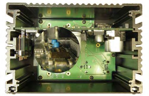
Dip switch S1 and momentary switches SW2 & SW3 are located on the main pc
board. Removal of the back plate is required to gain access (see Figure 14).
Pulsar 320 Manual 29Dip Switches: S1
Normal
Number Description Operation
State
1 Used to force firmware to stay in boot loader OFF
2 H8 Emulator enable OFF
Firmware write enable. Allows the H8 flash to be
3 OFF
written
Internal programming mode. Used to enable the
4 embedded flash programming algorithm. Need to be OFF
OFF for initial loading of firmware over USB.
5 JTAG enable. Controls debugger mode on Cold fire.
OFF
Allows H8 Kernel to operate with USB power alone
Manufacturing EEPROM write protect. Needs to be
6 ON to allow manufacturing data to be written to the OFF
EEPROM
Momentary Switches: SW2, SW3
Normal
Number Description Operation
State
Manual reset for H8 Kernel. Resets the main N/A
SW2 (open)
microprosser
Manual reset for Cold fire Kernel. Resets the N/A
SW3 (open)
Ethernet communication microprocessor
Table 4: Internal Switch Functions
30 a d v a n c e d i l l u m i n a t i o n .c o mFigure 14: S1, SW2 & SW3 Locations
Note: SW2 & SW3 are not installed in some early production units.
Pulsar 320 Manual 319.0 Appendixes Appendix A: Trigger connection diagram Appendix B: Pulsar 320 Loader utility Appendix C: Installation Drawing Appendix D: TCP/IP Setup Instructions 32 a d v a n c e d i l l u m i n a t i o n .c o m
Appendix A

 Appendix A: Figure 15 Trigger Connection Diagram

                     Pulsar 320 Manual              33
34
a d v a n c e d i l l u m i n a t i o n .c o m
Appendix A - Figure 16: Cognex Connection Diagram Appendix A - Figure 17: IPD Connection DiagramPulsar 320 Manual
35
Appendix A - Figure 18: IPD Connection DiagramAppendix B
Appendix B - Figure 19: Pulsar 320 Loader Utility
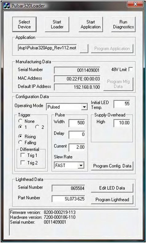
36 a d v a n c e d i l l u m i n a t i o n .c o mSELECT DEVICE:
- Connects to target Pulsar-320 (USB)
START LOADER:
- Allows firmware to be flashed to memory: internal use only
- Provides access to ‘Manufacturing Data’: DIP switch ‘S1’ must have position
6 ENABLED in order to program
manufacturing data
START APPLICATION:
- Resets the H8 and refreshes the USB connection
RUN DIAGNOSTICS:
- Performs a low-level diagnostic test: Internal use only
APPLICATON:
- Loader for firmware: Internal use only
MANUFACTURING DATA:
- Serial Number: Factory Set
- MAC Address*: Factory Set
*MAC Addresses are provided by the IEEE. Any adjustments to this address may cause
conflicts with other equipment not related to this product. Advanced illumination as-
sumes NO responsibility for conflicts caused by this parameter being changed from its
factory setting*
- Default IP: Factory Set 192.168.24.240
- 48V limit: Limits output voltage from the
pulsar to 48V
CONFIGURATON DATA:
- Initial LED Temp*: Factory Set
*This parameter contains information that could be harmful to the attached light head if
altered. Advanced Illumination assumes NO responsibility for damaged products if this
parameter is changed from factory settings without prior approval*
- Supply Overhead: Factory Set
- Operating Mode/Trigger/Pulse: Low-level user interface
- Slew Rate: Adjusts the On-time response of
the pulse. Use to compensate for
high EMI situations
- Differential (Trig1 & Trig2): Check to enable differential triggers
- Program Config. Data: stores all changes to this section into
memory
Pulsar 320 Manual 37LIGHTHEAD DATA*: *This section contains information that could be harmful to the attached light head if altered. Advanced illumination assumes NO responsibility for damaged products if any information in this section is changed from factory settings without prior ap- proval* - Serial number: Light head serial number factory set - Part Number: Light head part number - Edit LED Data: Opens the Signatech 2 parameters dialog - Program Lighthead: Stores the Signatech 2 parameters into the light head EEPROM 38 a d v a n c e d i l l u m i n a t i o n .c o m
POWER/TRIGGER/COMMUNICATION CABLE INTERFACE              4.7                    98.8                      8.0
                                                                                                                                 (0.19)                 (3.89)                    (0.32)

                                                                                                                                                                                       MOUNTING SURFACE
                                                                                                                                                                                                          Appendix C:

                                                                                                                                      50.8               14.3

                    Appendix C - Figure 20: Installation Drawings
                                                                    DIN RAIL MOUNTING BRACKET                                        (2.00)             (0.56)
                                                                                                                                          4.                        5.

                                                                                                                                                 5.   9/16 INCHES MINIMUM SPACE REQUIRED FOR
                                                                                                                                                      DIN RAIL INSTALLATION.

Pulsar 320 Manual
                                                                                    129.6                           34.6
                                                                                    (5.10)                         (1.36)                             2 INCHES MINIMUM SPACE REQUIRED FOR POWER/
                                                                                                                                                 4.
                                                                                                                                                      TRIGGER/COMMUNICATION CABVLE INSTALLATION.

                                                                                                                                                      UNIT MUST BE INSTALLED IN SUCH A WAY AS
                                                                                                                                                 3.   TP PROVIDE ADEQUATE AIR FLOW TO ENSURE
                                                                                                                         47.7                         AGAINST OVERHEATING.
                                                                                                                        (1.88)
                                                                                                                                                 2.   UNIT MAY BE MOUNTED IN ANY POSITION.
                                                                                                                                                 1.   UNIT WEIGHT: 1.610 LB/ .730 KG
                                                                                                    56.9
                                                                                                   (2.24)
                                                                                                    85.6

       39
                                                                                                   (3.37)                                 APPENDIX C: FIGURE 14 INSTALLATION DRAWINGS
Appendix D:
Pulsar 320 TCP/IP Setup Instructions
Appendix D Contents:
1.0 Configure network settings for the PC
- Connect through a network or router
- Direct connect with a single PC connection
2.0 Connection to the Pulsar 320
- Pulsar 320 TCP/IP setup
TCP/IP Connection through network to Pulsar 320:
PC Setup
Find your current IP address and determine whether it is static or dynamic:
1. Open Windows Start menu
2. Select Run
3. Type: cmd and click OK
4. At the blinking cursor, type: ipconfig/all and press Enter
5. Look for these entries near the end of the list:
- Dhcp enabled. “No” means your IP address is static. “Yes” means it
is dynamic.
- IP Address. This is your current IP address
- Subnet Mask. This is the local subnet range
- Default Gateway. Gateway address of any routers or hubs.
Appendix D - Figure 21: Windows IP Configuration
40 a d v a n c e d i l l u m i n a t i o n .c o mIf the current IP address is:
Static, then this IP will need to be changed to Dynamic by enabling DCHP.
Dynamic, then take note of: IP Address, Subnet Mask, Default
Gateway, then continue to Pulsar Setup.
Enable DHCP (Windows XP)
1. Open Windows Start Menu
2. Open Control Panel
3. Classic view: Open Network Connections
Category view: Select Network and Internet Connections, and
then Network Connections
4. Double-click on your active LAN or Internet connection
5. Click Properties
This opens the Local Area Connections Properties window.
Appendix D - Figure 23: Internet Protocol
Properties
Appendix D - Figure 22: Local Area Properties
6. Enable Obtain IP address automatically. Enable Obtain
DNS automatically unless advised otherwise by your network
administrator.
Pulsar 320 Manual 41Direct TCP/IP connection from single PC to Pulsar320
PC Setup
You will need to assign a static IP to the host PC
Find your current IP address and whether it is static or dynamic:
1. Open Windows Start menu
2. Select Run
3. Type: cmd and click OK
4. At the blinking cursor, type: ipconfig/all and press Enter
5. Look for these entries near the end of the list:
- Dhcp Enabled. “No” means your IP address is static. “Yes”
means it is dynamic.
- IP Address: This is your current IP address.
- Subnet Mask. This is the local subnet range.
- Default Gateway. Gateway address of any routers or hubs.
Appendix D - Figure 24: Windows IP Configuration
42 a d v a n c e d i l l u m i n a t i o n .c o mIf the current IP address is:
- Static, then make note of the IP address, subnet mask, and default
gateway. You will need to assign the Pulsar 320 network settings so they work
in the same range.
- Dynamic, then assign a static IP address instead (covered in the following
pages).
If your IP is already Static, then you can skip to Pulsar Setup. You only need to
do these steps if you want to adjust any of the TCP settings (IP, Gateway, Subnet).
Choose an IP Address
Choose an IP address, and collect other information needed in order to assign a
static IP address to your computer.
This only needs to be done if you have a router with multiple PCs and/or other
devices connected with different IP addresses.
In your router administration program, find an IP address that can be
assigned as a static IP. The address:
- Must not be one that might be assigned to someone as a dynamic
address.
- Must not be one that has been assigned to another device
- Must be lower than the range of dynamic addresses.
This may be handled by an administrative group or network engineers. Have
this group assign an IP that you can use for both the host PC and target Pulsar
320 unit. This will prevent any IP conflicts from occurring.
Assign the IP Address to the PC (Windows XP)
To set a static IP address:
1. Open Windows Start menu
2. Open Control Panel
Pulsar 320 Manual 433. Classic view: Open Network Connections
Category view: Select Network and Internet Connections, and then
Network Connections
4. Double-click on your active LAN or Internet Connection
5. Click Properties
This opens the Local Area Connections Properties window
6. In the General tab, highlight the Internet Protocol (TCP/IP) item,
and click Properties.
This opens the Internet Protocol (TCP/IP) Properties window.
7. In the General tab, click Use the following IP address, and then
enter:
- IP address. The static IP address you want to assign to this
computer.
- Subnet Mask. Subnet Mask used used by your router.
- Default Gateway. IP address of your router’s default gateway.
8. In Use the following DNS server addresses, enter all the IP
addresses for the DNS servers your router uses if applicable.
If DNS server addresses do not pertain to you, use Obtain DNS server
address automatically.
9. Click OK
Then:
10. Click OK to close each window
11. Restart your computer
12. Recheck your IP address again, to make sure the changes were
applied.
Run: cmd Type: ipconfig/all
Continue to Pulsar Setup
44 a d v a n c e d i l l u m i n a t i o n .c o mPulsar Setup
Once we know what the system and network settings are, we can configure the
Pulsar 320 controller to communicate across the network via TCP/IP.
Appendix D - Figure 25: USB Port Configuration
Connect to the Pulsar 320
The Pulsar must first be configured via USB.
1. Connect the target Pulsar 320 unit via USB cable to host PC
2. Connect 24VDC power source and toggle the controller ON
3. Launch “PulsarV00_02.exe”
4. In the parent window, select the USB icon to establish a USB
connection
This will open the USB port select dialog.
5. Select the USB port to connect to -- usually port 0 for a single Pulsar
6. Once connection is established, select Query
7. In the information box you can view current IP, Subnet, Gateway,
and other pertinent information regarding current settings on
the controller.
8. To edit network settings press Edit Network
9 Before assigning a new IP address you must choose and IP
address that won’t conflict with any other devices on the
network (PCs, printers, routers, other machines, etc.).
For most small networks with10. Subnet Mask is a division of networks into separate pieces.
Essentially you will want both host PC and Pulsar 320 to be on
the same subnet so they can find each other.
Enter the value found from your PC settings.
Example:
PC Subnet: 255.255.255.0
Pulsar 320 Subnet: 255.255.255.0
Appendix D - Figure 26: Pulsar TCP/IP Connection
and IP Dialog Window
The subnet also determines how many unique places are used in IP address.
Contact your network administrator if you need more assistance.
11. Enter the same value obtained from the PC for default gateway
into the Pulsar 320
PC Default Gateway 192.168.24.1
Pulsar 320 Subnet 192.168.24.1
12. Press OK
13. Close the Query Dialog and close the USB connection
14. Power down the Pulsar 320 and disconnect the USB cable
15. Connect the Ethernet cable and power the Pulsar ON again
16. Select the TCP/IP icon to open the ECP/IP connection dialog
46 a d v a n c e d i l l u m i n a t i o n .c o m17. Press ADD to add a new device to the list.
18. Name the device for easy recognition and enter all the proper IP
settings that were loaded onto the controller. Once finished,
press OK
19. Select the newly added device and press Connect to establish
the TCP/IP connection to that device.
Pulsar 320 Manual 47a d v a n c e d i l l u m i n a t i o n .c o m
You can also read