Design and Fabrication of Random Metal Foam Structures for Laser Powder Bed Fusion - MDPI
←
→
Page content transcription
If your browser does not render page correctly, please read the page content below
materials
Article
Design and Fabrication of Random Metal Foam
Structures for Laser Powder Bed Fusion
Nicola Contuzzi 1 , Sabina Luisa Campanelli 1 , Fabrizia Caiazzo 2, *             and Vittorio Alfieri 2
 1   Dip. di Meccanica, Matematica e Management—Politecnico di Bari, Viale Japigia 182, 70126 Bari (BA), Italy;
     nicola.contuzzi@poliba.it (N.C.); sabinaluisa.campanelli@poliba.it (S.L.C.)
 2   Dip. di Ingegneria Industriale—Università degli Studi di Salerno, Via Giovanni Paolo II 132,
     84084 Fisciano (SA), Italy; valfieri@unisa.it
 *   Correspondence: f.caiazzo@unisa.it

 Received: 12 March 2019; Accepted: 17 April 2019; Published: 20 April 2019

 Abstract: With the development of additive manufacturing, the building of new categories of
 lightweight structures such as random foams have been offered. Nevertheless, given the complexity
 of the required parts, macroscopic defects may result or the process may even fail. Therefore,
 proper actions must be taken at the design stage. In this paper, a method of design for additive
 manufacturing (DfAM) to build metal random foam structures is proposed. Namely, a procedure is
 suggested to generate a structure that has interconnected porosity. This procedure is based on the
 aimed fractional density and several technical requirements, and then the geometry is optimized
 and meshed. To validate the algorithm, a test article consisting of a metal cylinder with spherical
 random pores ranging from 1 to 6 mm in diameter with a resulting fractional density of 40 ± 2% has
 been conceived and manufactured by means of laser powder bed fusion (LPBF). On the basis of the
 outcome of the manufacturing process, crucial information has been gathered to update the algorithm.

 Keywords: additive manufacturing; design for manufacturing; random foam structures

1. Introduction
     Lightweight metal structures are widely used in aeronautics, automotive, biomedical [1], energy,
and bionics [2] fields. Namely, high strength-to-weight ratio, thermal and acoustic insulation, good
properties of energy absorption, and even electromagnetic shielding [3] benefit when metal cellular
materials are considered [4].
     For the purpose of designing and building, many different approaches have been discussed in
the literature. Interestingly, the concept has been significantly addressed in the field of additive
manufacturing (AM), as state-of-the-art and flexible processes have been developed that offer
new opportunities in terms of shapes, sizes, geometric mesostructures, material compositions,
and microstructures, and therefore improve both performance and life-cycle. Design for additive
manufacturing (DfAM) has been introduced for the purpose of exploiting all the opportunities in
AM [5,6]. By considering this, the production of freeform complex structures using potentially a wide
range of materials, including high-performance metals, has been allowed [7,8].
     Periodic structures are the most common cellular materials, given their capability to provide
variations in the structural properties and benefit controllable deformation. With respect to this
subject, several methods for designing lattice structures with controlled anisotropy are reported [9].
As a matter of fact, lattice-truss structures are affected by anisotropy resulting in weaker directions
depending on the arrangement of the trusses [10]. Nevertheless, since the direction of loading is not
known in advance of the specific applications (e.g., aerospace or medical), a lightweight structure is
required to exhibit a similar homogeneous mechanical behavior, hence the foams, i.e., samples with

Materials 2019, 12, 1301; doi:10.3390/ma12081301                                www.mdpi.com/journal/materials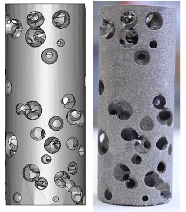
Materials 2019, 12, 1301                                                                            2 of 13

random pore distribution [11], represent a valid alternative to lattice-truss structures. On the other
hand, the conventional production of foams is currently limited to low-melting-point metals, such as
aluminum or copper. Consequently, other materials with higher strength must be investigated, and
therefore AM processes represent a valid alternative and are worth investigating for this purpose.
      In general, foam samples are designed using the reconstruction methods of either statistical or
stochastic, for example, a three-dimensional porous media is created from two-dimensional (2D) images
or a three-dimensional (3D) cloud of data points [12]. In this context, scanning electron microscopy [13],
computed tomography, and X-rays scanning have been considered [14] to generate the models. Then,
different fabrication techniques can be compared. In the literature, the methods of bubbling gas or
injecting a foaming agent in the molten alloy are referred to as conventional approaches [3], and
in the latter, expanding hydrogen is released, and therefore used to create pores [15]. Reviews of
other consolidated technologies such as the space-holder method [16] or the continuous zone melting
technique [17] are available in the literature. When moving to more recent methods, AM is certainly
suitable due to its advantages. For example, with specific reference to the building of metal random
foam structures, the advantage of control over size, density, and local distribution of the designed
porosity is documented [3]. In particular, layer-by-layer AM building (i.e., two-stage processing)
is expected to provide higher accuracy as compared with directed deposition AM (i.e., one-stage
processing) [18]. The feasibility of manufacturing similar-to-foam steel components with spherical
porosity adopting laser powder bed fusion (LPBF) has been explored [4], but limited research has been
devoted to the manufacturing of metal random foam structures, which have some issues that must
be addressed. First, interconnected porosity is mandatory in order to allow the extraction of loose
powder from cavities. Moreover, a proper size of pores is required to comply with the manufacturing
capability of the building machine to prevent inner supporting structures [19], which otherwise should
be removed in post-processing.
      To address this lack of knowledge, porous structures with random spherical pores and controlled
fractional density are designed and manufactured in this article. A DfAM approach is proposed
and the main issues are discussed. Namely, a three-dimensional porous structure is conceived with
given porosity, then the geometry is converted to optimized points and eventually meshed. Possible
errors, in terms of shapes and poor contours, are corrected. Prior to manufacturing, the structure
is checked layer-by-layer to assess its effective manufacturability. During manufacturing via LPBF,
several post-processing checks are conducted, and then crucial findings are drawn to update the
algorithm for random foam generation.

2. Materials and Methods

2.1. Design of a Random Foam
     Due to their random distribution of pores, foams have a complex internal structure and indeed
thin walls and a large empty volume of up to 90% could be required. Consequently, building via AM
techniques is challenging and there is a high probability of faulty parts. Therefore, a proper strategy at
the design stage should be adopted. For this purpose, three rules were proposed when LPBF is used:

•     Interconnection of inner pores is mandatory.
•     A minimum solid fraction preventing the collapse of the structure must be offered at any layer.
•     The wall thickness must be larger with respect to the effective melting diameter.

     The first rule is a technical requirement for the extraction of the residual metal powder. The second
and third rules are conceived to allow effective, rather than ineffective, manufacturing of the parts.
For example, a sensible balancing between solid fraction and connected pores (Figure 1) is required
to prevent collapse of the structure under its own weight where inner supporting structures must be
avoided. Moreover, a minimum size of bulky material must be allowed between adjacent pores to offer
local strength to effectively support the next building layers.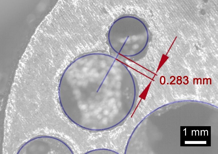
Materials 2019, 12, 1301                                                                              3 of 13
Materials 2019, 12, x FOR PEER REVIEW                                                                  3 of 13

            Figure1.1. Cross-section
            Figure     Cross-section of
                                     ofaasample
                                          samplewith
                                                withreduced
                                                     reducedsolid
                                                             solidfraction
                                                                   fractiondue
                                                                            dueto
                                                                                toconnected
                                                                                   connectedpores.
                                                                                             pores.

     With respect to the third rule, the effective melting diameter of the laser beam must be evaluated
      With respect to the third rule, the effective melting diameter of the laser beam must be evaluated
in advance via preliminary quality job [6] in order to assess the actual resolution of the process, walls
 in advance via preliminary quality job [6] in order to assess the actual resolution of the process, walls
thinner than the actual size of a single scanning line are not possible. Further investigation resulting in
 thinner than the actual size of a single scanning line are not possible. Further investigation resulting
additional precautions and guidelines for design are reported in the relevant section of this article.
 in additional precautions and guidelines for design are reported in the relevant section of this article.
2.1.1. Generating the Solid Model
 2.1.1. Generating the Solid Model
      At first, to design a random foam, a flowchart was proposed (Figure 2). The algorithm was
       At first, to design a random foam, a flowchart was proposed (Figure 2). The algorithm was fed
fed with crucial input data, i.e., a range for the pore size, and the aimed fractional density of the
 with crucial input data, i.e., a range for the pore size, and the aimed fractional density of the foam
foam and the wall thickness depending on the accuracy and the resolution of the printing machine.
 and the wall thickness depending on the accuracy and the resolution of the printing machine. The
The driving idea was to build the CAD model by means of piling up N modelling layers, which were
 driving idea was to build the CAD model by means of piling up N modelling layers, which were
required to comply with the referred building rules and the aimed fractional density. The number
 required to comply with the referred building rules and the aimed fractional density. The number of
of modelling layers was based on the height of the structure being designed, as well as the available
 modelling layers was based on the height of the structure being designed, as well as the available
computing power. Calculations were performed using a developed macro software (Excel, 2016,
 computing power. Calculations were performed using a developed macro software (Excel, 2016,
Microsoft, Redmond, WA, USA), where the range of the pore diameter was given and a cloud of
 Microsoft, Redmond, WA, USA), where the range of the pore diameter was given and a cloud of
random pore centers was generated (Figure 3) in a cylindrical coordinate system within each the layers,
 random pore centers was generated (Figure 3) in a cylindrical coordinate system within each the
from layer 1 to N. Spherical pores of random size were provided (see Figure 4), in compliance with
 layers, from layer 1 to N. Spherical pores of random size were provided (see Figure 4), in compliance
both the constraints of fractional density and the wall thickness. If the condition of interconnection
 with both the constraints of fractional density and the wall thickness. If the condition of
was matched, the next modelling layer was generated, otherwise, the current layer was deleted and
 interconnection was matched, the next modelling layer was generated, otherwise, the current layer
regenerated. The process was repeated up to the actual size of the sample. Then, a final check on the
 was deleted and regenerated. The process was repeated up to the actual size of the sample. Then, a
interconnection was conducted. Eventually, the solid CAD model was generated.
 final check on the interconnection was conducted. Eventually, the solid CAD model was generated.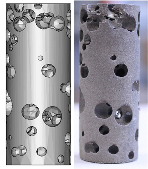
Materials 2019,
Materials       12, x1301
          2019, 12,   FOR PEER REVIEW                                                           44 of
                                                                                                   of 13
                                                                                                      13
Materials 2019, 12, x FOR PEER REVIEW                                                            4 of 13

                                                             THICKNESS
                FULL PART               calculate N        of the modelling
                                                              THICKNESS
                                                                 layer
                FULL PART               calculate N         of the modelling
                                                                  layer

                                        initialize
                                    the layer   id x=0
                                         initialize
                                     the layer id x=0

                                           x+1
                                           x+1

                                                                 model         y
                                           x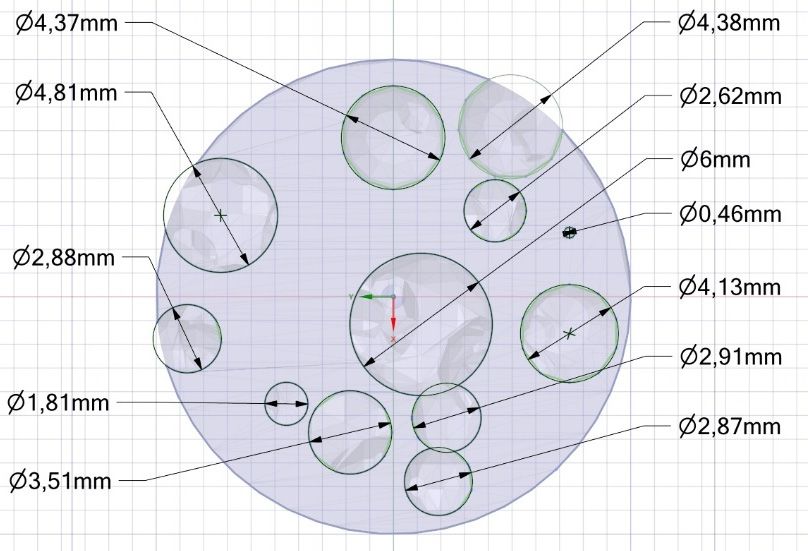
Materials 2019, 12, x FOR PEER REVIEW 5 of 13
Materials
Materials2019,
2019,12,
12,x1301
FOR PEER REVIEW 55of
of13
13
Materials 2019, 12, x FOR PEER REVIEW 5 of 13
Figure 4. Generation of spherical pores for the current modelling layer, with resulting porous
structure.
Figure 4. Generation of spherical pores for the current modelling layer, with resulting porous
structure.
Figure 4.4.Generation
Generationofof spherical
spherical pores
pores forcurrent
for the the current modelling
modelling layer,
layer, with with resulting
resulting porous
porous structure.
2.1.2.structure.
Generating the STL File
2.1.2. Generatingthe
2.1.2. Generating theSTLSTLFileFile
A number of steps must be addressed to effectively build the part via AM, irrespective of the
2.1.2.A
AGenerating
number of
manufacturing
number ofthe STL
steps
technology.
steps File
must
must be addressed
Indeed,
be addressed
a proper tomesh
to effectively build the
was required
effectively build theandpart
part was viaprovided
via AM, irrespective
AM, irrespective of the
to the printing
of the
manufacturing
machine
manufacturing
A number technology.
via antechnology.
STL
of steps(standard
must Indeed,
Indeed, aaproper
betriangle proper
addressed mesh
language)
tomesh was[20].
file
was
effectively required
required
build and
Therefore,
and
the partwas
atvia
was provided
first
AM, to the
the
theirrespective
provided solid
to modelprinting
ofwas
printingthe
machine
converted
machine via
viain an
ana STL
point
STL (standard
cloud
(standard to be triangle
meshed
triangle language)
at next
language) file
step,
file [20].
points
[20]. Therefore,
located
Therefore,
manufacturing technology. Indeed, a proper mesh was required and was provided to the printing on at
atthefirst the
outside
first the solid
skin
solid model
of the
model was
solid
was
converted
CAD
converted
machine model inaand
in
via aanpoint
point
STL cloud
strategically
cloud to be
to
(standard be meshedalong
gathered
meshed
triangle at next
at next
language) step,
step, points
high-curvature
filepoints located
surfaces.
[20]. located
Therefore, on the
on thefirst
at outside
Nevertheless,
outside skin
skin
the solid whenof
of the
the
model solid
shifting
solid
was
CAD
this
CAD model
method
model
converted and
to
inand strategically
a strategically
random
a point cloudfoam gathered
structure
gathered
to be along
meshedalong at high-curvature
(Figure 5), many
high-curvature
next step, points surfaces.
points were
surfaces.
located Nevertheless,
generated
onNevertheless,
the outside and when
skinmost
when of theshifting
of them
shifting
solid
this
were
this
CAD method
redundant
method
modelto to
and aa random
random
and
strategically foamgathered
ineffective
foam structure
structure (Figure
to the overall
(Figure
along 5), many
precision.
5), many
high-curvature points
Therefore,
points were
were generated
the generated
surfaces. general and most
method
Nevertheless, and most
was of
when of them
deemed
them
shifting
were
to
were redundant
thisbemethod
time consuming
redundant and
to aand ineffective
andfoam
ineffective
random to
to the
the probabilityoverall
the overall
structure precision.
ofprecision.
(Figuregenerating
5), many Therefore,
defects
points in
Therefore, the
the
were general
thegeneral
mesh and
generated method
method was
specific
and deemed
was errors
most deemed
of them of
to
to be
inverted
be time
time consuming
normal
consuming vectors and
and or the
bad
the probability
edges
probabilitywas of
of generating
expected
generating to bedefects
high.
defects
were redundant and ineffective to the overall precision. Therefore, the general method was deemed in
With
in the
the a mesh
goal
mesh and
of
and specific
optimized
specific errors
cloud
errors of
of
inverted
points,
inverted
to be time normal
the vectors
approach
consumingvectors of or
or
and bad
theedges
Pauly
bad [21] was
edges was
was
probability expected
referred
expected totobe
of generating toandhigh. WithWith
bedefects
high. a goal
implemented.
in the of optimized
Using
a goal
mesh ofand cloud cloud
thisspecific
method
optimized of points,
which
errors of
of
the approach
considers
points,
inverted the of Pauly
incremental
approach
normal vectors [21]
ofandor was
Pauly referred
hierarchical
bad[21]edgeswaswasto and implemented.
clustering,
referred
expectedtoiterative
and Using
With this
simplification,
to beimplemented.
high. method
Using
a goal and
ofthis which
particle
method
optimized considers
simulation
which
cloud of
incremental
algorithms
considers
points, the andcreate
to
incrementalhierarchical
approach andPauly
of clustering,
approximations
hierarchical
[21] was iterative
of
clustering,
referred simplification,
point-based models,
iterative
to and and
the particle
number
simplification,
implemented. simulation
of points
and
Using particle algorithms
significantly
this method simulation
whichto
create
decreased
algorithmsapproximations
(Figure
to create
considers incremental 6), theof point-based
geometry
approximations
and hierarchical models,
wasofnot the
point-based
clustering, number
affected iterative
and of points
the occurrence
models, significantly
the number
simplification, of noise decreased
of points
and particlewas (Figure
reduced.
significantly
simulation 6),
the geometry
decreased
algorithms towas
(Figure notthe
6),
create affected
geometry and was
approximations the occurrence
affectedofand
notpoint-based
of noise thepoints
models, wasnumber
occurrence
the reduced.
of noise of points
pointswas reduced.
significantly
decreased (Figure 6), the geometry was not affected and the occurrence of noise points was reduced.
Figure 5. Point cloud for a cubic random foam structure.
Figure5.
Figure Pointcloud
5.Point cloudfor
foraacubic
cubicrandom
randomfoam
foamstructure.
structure.
Figure 5. Point cloud for a cubic random foam structure.
Figure 6.
Figure Processing aa cloud
6. Processing cloud of
of points
points using
using the
the approach
approach of
of Pauly.
Pauly.
Figure 6. Processing a cloud of points using the approach of Pauly.
Figure 6. Processing a cloud of points using the approach of Pauly.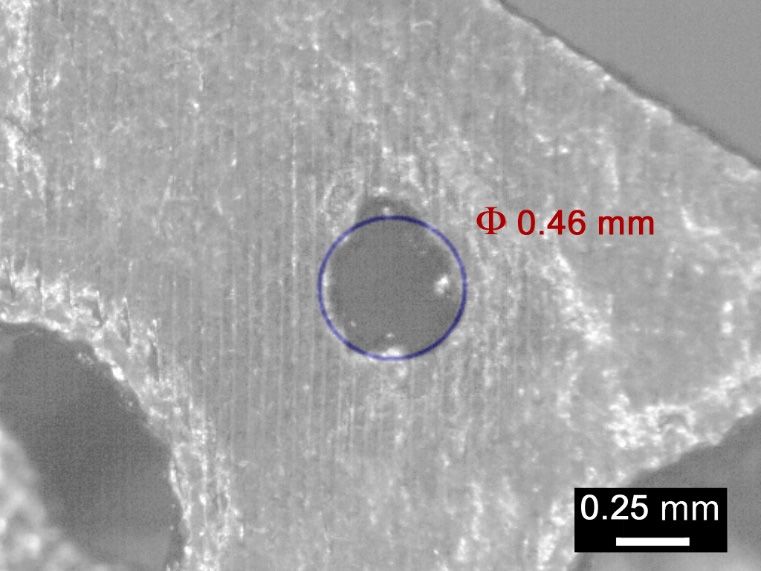
Materials 2019, 12, 1301
x FOR PEER REVIEW 6 of 13
The second main step was meshing the cloud of points. The constrained Delaunay triangulations
(CDT)The second
[14] main as
was used step a was meshing
reference andthe cloudconveniently
it was of points. The constrained
adjusted to meetDelaunay triangulations
the requirements of
(CDT) [14] was used as a reference and it was conveniently adjusted to meet
building using a foam structure, where distortion of triangles may result around the pores. As the requirements of
building
expected,using a foam structure,
a mismatch was foundwhere distortion
between of triangles
the theoretical may result
original around
spherical the pores.
surface in the As expected,
solid model
a
and its approximation upon triangularization, i.e., a chordal error resulted on each pore and and
mismatch was found between the theoretical original spherical surface in the solid model had its
to
approximation upon triangularization,
be reduced to improve the quality of thei.e., mesh.
a chordal
To error resulted on
this purpose, new each pore and
vertices had to
needed to be
bereduced
created
to improve
when the quality
the chordal error of the mesh.
exceeded To thisthreshold.
a certain purpose, However,
new vertices
theneeded
elementtosize be created
used to when
achievethea
chordal error exceeded a certain threshold. However, the element size used
given limit chordal error may have been very small, and therefore refining the mesh would have to achieve a given limit
chordal
resulted error may have
in increased been very small,
unmanageable and therefore
geometrical data. refining
One may theassume
mesh would have resulted
the chordal error wasin
increased unmanageable geometrical data. One may assume the chordal error
accepted when the order of magnitude of the accuracy of the printing process was matched. was accepted when the
orderAdditionally,
of magnitudegeneral
of the accuracy of the
errors such printing outpointing
as inverted process was normal
matched. vectors and poor connections
Additionally, general errors such as inverted outpointing normal
of edges had to be addressed, which involved regenerating the triangle and stitching vectors and poorthe connections
vertexes,
of edges had to be addressed, which involved regenerating the triangle and
respectively. In general, for foam structures there was no need for specific guidance in additionstitching the vertexes,
to
respectively. In general, for foam structures there was no need for specific
the common rules for smoothing [22]. The STL file was then sliced before processing. guidance in addition to the
common rules for smoothing [22]. The STL file was then sliced before processing.
2.1.3. Slicing the Model
2.1.3. Slicing the Model
Once the building direction had been set for the building layers, the solid 3D part was converted
Once the building direction had been set for the building layers, the solid 3D part was converted to
to 2D slices. The total number of slices depended on the overall height of the structure and the
2D slices. The total number of slices depended on the overall height of the structure and the thickness
thickness of the building layer, which was different from the thickness of the modelling layer. In
of the building layer, which was different from the thickness of the modelling layer. In LPBF, the latter
LPBF, the latter was a compromise between the penetration depth of the laser beam and the mean
was a compromise between the penetration depth of the laser beam and the mean particle size of the
particle size of the metal powder to lay [23].
metal powder to lay [23].
Thin lines in each slice could result in manufacturing defects when the laser beam was scanned
Thin lines in each slice could result in manufacturing defects when the laser beam was scanned
along it, and therefore additional actions were taken for the purpose of manufacturability. For each
along it, and therefore additional actions were taken for the purpose of manufacturability. For each
layer, the wall thickness, i.e., the gap between adjacent pores, was considered and compared to the
layer, the wall thickness, i.e., the gap between adjacent pores, was considered and compared to the
actual resolution of the building process, which depended on the effective melting diameter. When
actual resolution of the building process, which depended on the effective melting diameter. When
the threshold had not been matched, the radius of the adjacent pores was reduced (Figure 7) to allow
the threshold had not been matched, the radius of the adjacent pores was reduced (Figure 7) to allow
effective building of a solid gap. Upon correction, any change to the fractional density was negligible.
effective building of a solid gap. Upon correction, any change to the fractional density was negligible.
Figure 7. Gap between adjacent pores, before and after correction of the wall thickness.
Figure 7. Gap between adjacent pores, before and after correction of the wall thickness.
2.2. Manufacturing of the Foams
2.2. Manufacturing
An EOSINT M270of the laser
Foamssintering system (EOS, Krailling, Germany) with Yb-fibre laser source
was used to manufacture
An EOSINT the sintering
M270 laser test article. A prealloyed,
system argon-atomized
(EOS, Krailling, Germany) virgin
with commercial EOS
Yb-fibre laser GP1
source
stainless
was usedsteel powder, 36the
to manufacture mean
µmtest grain
article. A size, corresponding
prealloyed, to standard
argon-atomized UNS
virgin S17400 chromium
commercial EOS GP1
copper precipitation hardening steel in terms of nominal chemical composition
stainless steel powder, 36 μm mean grain size, corresponding to standard UNS S17400 was usedchromium
[6]. High
strength, good corrosion resistance, ◦ C, and
copper precipitation hardening steelgood mechanical
in terms of nominalproperties
chemicalat composition
temperatureswasup used
to 316[6]. High
good toughness were offered. Indeed, this material is generally used in chemical and
strength, good corrosion resistance, good mechanical properties at temperatures up to 316 °C, andpetrochemical
industry, as well were
good toughness as in aerospace and marine,
offered. Indeed, food processing
this material and
is generally power
used plants [24].
in chemical and petrochemical
industry, as well as in aerospace and marine, food processing and power plants [24]. trials aimed to
Processing parameters (Table 1) and scanning strategies were based on preliminary
optimize the process
Processing for the purpose
parameters (Table 1)ofand
a full dense structure.
scanning strategiesAn
wereaccuracy of 0.02
based on mm and trials
preliminary a minimum
aimed
to optimize the process for the purpose of a full dense structure. An accuracy of 0.02 mm and a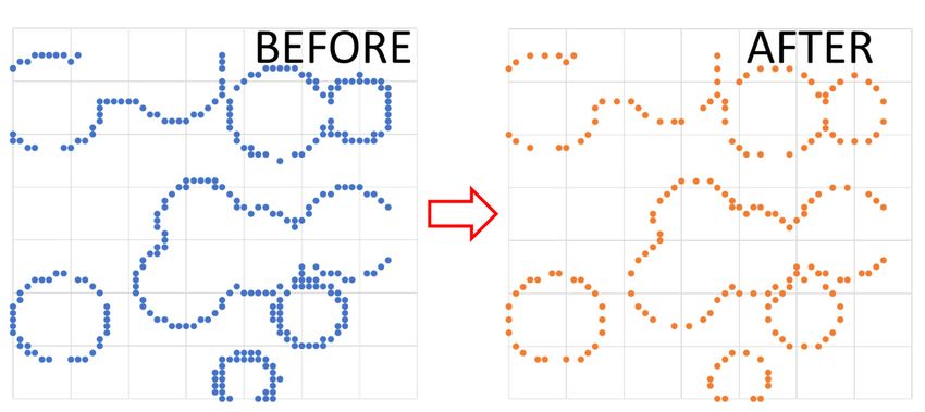
Materials 2019, 12, 1301 7 of 13
Materials 2019, 12, x FOR PEER REVIEW 7 of 13
minimum size ofdiameter
size of building buildingofdiameter
0.190 mmof 0.190
were mm wereand
checked checked
theseand
werethese
usedwere used tothe
to address address
issuesthe
of
issues
chordaloferror
chordal
and error and wall thickness,
wall thickness, respectively,
respectively, although
although the the mechanical
mechanical stability
stability during during
building is
building is highly dependent on geometry and must be discussed on
highly dependent on geometry and must be discussed on a case-by-case basis.a case-by-case basis.
To
To prevent
prevent oxidation
oxidation during
duringthe
theprocess,
process,a controlled nitrogen
a controlled atmosphere
nitrogen atmospherewaswas
arranged, the
arranged,
oxygen content
the oxygen being
content taken
being below
taken 0.8%.
below 0.8%.
Table 1.
Table 1. Processing parameters in
Processing parameters in laser
laser powder
powder bed
bed fusion
fusion (LPBF)
(LPBF) of
of EOS
EOS GP1
GP1 stainless
stainless steel
steel powder.
powder.
Factor
Factor Value
Value
Laser
Laser power
power 195
195WW
Scanning speed
Scanning speed 0.75 m/s
0.75 m/s
Hatch
Hatch spacing
spacing 100 μm
100 µm
Scan length
Scan length 2020
mmmm
Layer thickness
Layer thickness 2020
μmµm
3. Results
3. Results and
and discussion
discussion
3.1. Modelling
3.1. Modelling of
of aa Cylindrical
Cylindrical Random
Random Pore
Pore Foam
Foam
To test
To test the
the algorithm
algorithm and and find
find any
any possible
possible strategy
strategy toto fix
fix the
the procedure,
procedure, aa metal
metal cylindrical
cylindrical
random pore foam has been considered. A nominal diameter of 20
random pore foam has been considered. A nominal diameter of 20 mm and height of 50 mm, mm and height of 50 mm, for
for aa
total volume 3
total volume of of 15700
15700 mmmm3,, have have been
been set.
set. Then,
Then, spherical
spherical random
random pores
pores have
have been
been generated
generated inin the
the
solid volume, the pore diameter has been conveniently set to range between
solid volume, the pore diameter has been conveniently set to range between 1 and 6 mm to prevent 1 and 6 mm to prevent
supporting in
supporting LPBF, the
in LPBF, the minimum
minimum allowed allowed diameter
diameter being
being 88 mm. The centers
mm. The centers of
of the
the pores
pores have
have been
been
generated in a cylindrical coordinate system aiming to a fractional density
generated in a cylindrical coordinate system aiming to a fractional density of 40 ± 2%. of 40 ± 2%.
For the
For the purpose
purpose of of generating
generating the the solid
solid model,
model, 20
20 modelling layers has
modelling layers has been
been chosen, each one
chosen, each one
being 2.5 mm thick. Three complete iteration cycles of the algorithm have been
being 2.5 mm thick. Three complete iteration cycles of the algorithm have been required to generate required to generate
the structure
the structure to to be
be built.
built. ItIt isisworth
worthnoting
notingthat
thatseveral
severalpores
poresintersecting
intersectingthe outer
the outer skin areare
skin required in
required
order
in to to
order allow
allow powder
powder ejection
ejectionduring
duringbuilding,
building,moreover,
moreover,as asrequired,
required,interconnection
interconnection among
among the
the
pores is mandatory (Figure
pores is mandatory (Figure 8). 8).
(a) (b)
(a) solid
Figure 8. Random pore foam: (a) solid fraction,
fraction, (b) distribution of pores.
A total
A total of
of 192
192 pores
pores has
has been
been generated
generated (Figure
(Figure 9)
9) and
and the
the highest
highest frequencies
frequencies of
of occurrence
occurrence have
have
been found
been found for
for the
the groups
groups with
with pore
pore size
size between
between 1.51.5 and
and 2.5
2.5 mm. On the
mm. On the other
other hand,
hand, the
the lowest
lowest
frequency resulted for the groups with pores ranging between 3.5 and 6.0 mm. Indeed, larger
frequency resulted for the groups with pores ranging between 3.5 and 6.0 mm. Indeed, larger pores pores are
unfavorable as they would result in reduced local strength, and therefore they would not comply
are unfavorable as they would result in reduced local strength, and therefore they would not comply with
the basic
with rules rules
the basic of theofalgorithm.
the algorithm.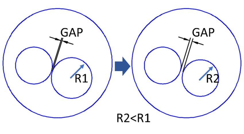
Materials2019,
Materials 2019,12,
12,1301
xx FOR
FOR PEER
PEER REVIEW
REVIEW 88 of
of 13
13
Materials 2019, 12, x FOR PEER REVIEW 8 of 13
60
60
60 50
50
pores
of pores
50 40
40
Number of pores
40 30
Number of
30
Number
30 20
20
20 10
10
10 0
0
0 1.0 -- 1.5
1.0 1.5 1.5 -- 2.0
1.5 2.0 2.0 -- 2.5
2.0 2.5 2.5 -- 3.0
2.5 3.0 3.0 -- 3.5
3.0 3.5 3.5 -- 4.0
3.5 4.0 4.0 -- 4.5
4.0 4.5
1.0 - 1.5 1.5 - 2.0 2.0 - 2.5 Pore
2.5
Pore size [mm]
- 3.0
size [mm]
3.0 - 3.5 3.5 - 4.0 4.0 - 4.5
Pore size [mm]
Figure 9.
Figure 9. Pore
Pore size
size distribution
distribution in
in the
the model
model of
of the
the random
random foam.
foam.
Figure 9. Pore size distribution in the model of the random foam.
Figure 9. Pore size distribution in the model of the random foam.
AA bulky
bulky 6579.06
6579.06 mmmm33 volume
volume resulted,
resulted, thus
thus yielding
yielding aa fractional
fractional density
density of
of 41.88%.
41.88%.
A bulky 6579.06 mm3 3volume resulted, thus yielding a fractional density of 41.88%. Interconnection
Interconnection
A bulky 6579.06
Interconnection of the
of themm
poresvolume
pores can be
can be checked
checked bythus
resulted,by means
means of virtual
virtual
yielding
of longitudinal
a longitudinal sectionsof
fractional density
sections (Figure 10) at
41.88%.
(Figure 10) at
of the pores can be checked by means of virtual longitudinal sections (Figure 10) at 25%, 50%, and 75%
25%, 50%, and
Interconnection 75%
25%, 50%, andof75% volume
the volume cut.
pores can be checked by means of virtual longitudinal sections (Figure 10) at
cut.
volume cut.
25%, 50%, and 75% volume cut.
Figure 10.
Figure 10. Virtual
Virtual longitudinal sections
Virtual longitudinal
longitudinal sections at
sections at 25% (A-A
at 25%
25% (A-A view),
(A-A view), 50%
view), 50% (B-B
50% (B-B view)
(B-B view) and
view) and 75%
and 75% (C-C
75% (C-C view)
view)
volume
Figure cut.
10. cut.
volume Virtual longitudinal sections at 25% (A-A view), 50% (B-B view) and 75% (C-C view)
volume cut.
Further checks
Further must be
checks must be conducted
beconducted
conductedonon transverse
ontransverse cross-sections,
transversecross-sections,
cross-sections,asasas
anan
an example,
example,
example, virtual cuts
virtual
virtual at 10
cuts
cuts at 10
at
10mm
mm mm and
Further
and 2525
and 25mmmm
checks height
height
must be
mm height are
areconsidered
considered
areconducted
considered (Figure
(Figure
on(Figure 11)
transverse11)when:
when: the
thesolid
solid
cross-sections,
11) when: the solidasfraction
fraction is
an example,
fraction is effective
effective
virtual
is effective to support
support
to cuts at 10
support the
the
mm next
next layers,
andlayers,
25 mm
layers, the
the wallsize
wall
height
the wall sizeconsidered
are
size exceedsaaaminimum
exceeds
exceeds minimum
(Figure 11)
minimum threshold
threshold
when: the
threshold of190
ofof 190µm,
solid
190 μm, and
and
fraction
μm, andthethe
is maximum
maximum
effective
the maximum chordal
tochordal
support error
error
chordal the
erroris
next is layers,
0.15
is 0.15
mm.
0.15 mm.
the wall size exceeds a minimum threshold of 190 μm, and the maximum chordal error
mm.
is 0.15 mm.
(a)
(a) (b)
(b)
Figure 11.
Figure Virtual (a)
11. Virtual transverse cross-sections
transverse cross-sections at
at (a) (b)mm
(a) 10
10 mm and
and(b)
(b)25
25mm
mmheight.
height.
Figure 11. Virtual transverse cross-sections at (a) 10 mm and (b) 25 mm height.
Figure 11. Virtual transverse cross-sections at (a) 10 mm and (b) 25 mm height.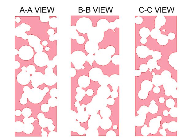
Materials 2019, 12, 1301 9 of 13
Materials
Materials2019,
2019,12,
12,xxFOR
FORPEER
PEERREVIEW
REVIEW 99ofof13
13
3.2.
3.2. Buildingofof
3.2.Building
Building ofaaaCylindrical
CylindricalRandom
Cylindrical RandomPore
Random Pore Foam
PoreFoam
Foam
The
The optimized
Theoptimized
optimizedSTL STL source
STLsource file
sourcefile has
filehas been
hasbeen used
beenused
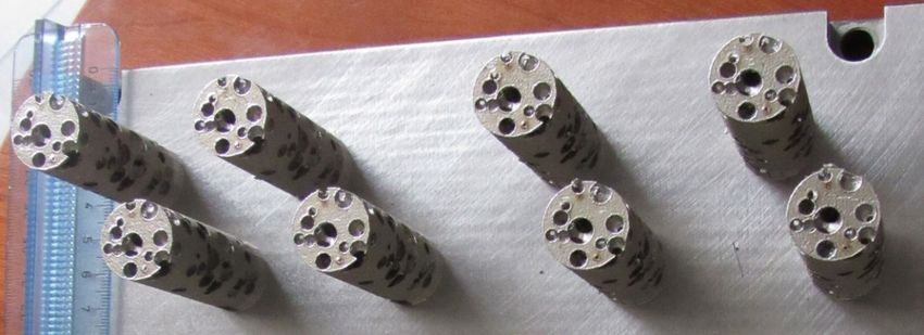
usedto to manufactureeight
tomanufacture
manufacture eight samples
eightsamples (Figure
samples(Figure
(Figure12)12) by
12)by means
bymeans
means
of
of LPBF,
ofLPBF, for
LPBF,for which
forwhich a natural
whichaanatural direction
naturaldirection
directionof of growth
ofgrowth
growthhashas been
hasbeen considered
beenconsidered
consideredwithwith the
withthe axis
theaxis of
axisof the
ofthe cylinders
thecylinders
cylinders
being
being orthogonal
orthogonaltotothe
beingorthogonal thebuilding
the buildingplate,
building plate,thus
plate, thuspreventing
thus preventing
preventing supporting
supporting
supportingstructures. The
structures.
structures.Thenominal
The nominalmodel
nominal has
model
model
been
has compared
been compared with the
with built
the foam
built (Figure
foam (Figure13), in
13), terms
in termsof pore
of size
pore and
size wall
and wallthickness,
has been compared with the built foam (Figure 13), in terms of pore size and wall thickness, aimingthickness,aiming
aimingto
check
to
tocheckthe
checkthe reliability
thereliabilityof the
reliabilityof building
ofthe
thebuilding process
buildingprocess and
processand possibly
andpossibly update
possiblyupdate the
updatethe design algorithm.
thedesign
designalgorithm.
algorithm.
Figure
Figure12.
12.Cylindrical
Cylindricalrandom
randomfoams
foamsmanufactured
manufacturedby
bymeans
meansof
ofLPBF.
LPBF.
LPBF.
(a)
(a) (b)
(b)
Figure13.
Figure 13. Comparing
Comparingthe
13.Comparing thenominal
nominalsolid
nominal solidmodel
solidmodeltoto
model the built
tothe
the foam,
built
built (a) (a)
foam,
foam, and (b) are
(a)and
and (b)views
(b) are of opposite
areviews
views of sides.
ofopposite
opposite
sides.
sides.
Transverse cross-cuts of the samples have been made at a given height (Figure 14). Since the
direction of building
Transverse
Transverse is parallel
cross-cuts
cross-cuts of thetosamples
ofthe the longitudinal
samples have
havebeen
beenaxis
madeof aatat
made sample,
aagiven
giventhese
heightcuts
height are made
(Figure
(Figure 14).in
14). a plane
Since
Since the
the
which
direction
directionis of
parallel
ofbuildingto the
building building
isisparallel
parallelto layer.
to the The resulting
thelongitudinal
longitudinal circular
axis
axisof cross-sections
ofaasample,
sample, these have
thesecuts
cuts arebeen
aremade
made compared
in
inaaplane to
plane
their
which counterpart
whichisisparallel
parallelto in
tothethe nominal
thebuilding
buildinglayer.model
layer.Theat the
Theresultingsame height
resultingcircular (Figure 15).
circularcross-sections To be
cross-sectionshave specific,
havebeen the
beencompared average
comparedto to
diameter
their of each circle
theircounterpart
counterpart in
inthe
the (i.e., each section
nominal
nominal modelof
model atatathe
pore)
the hasheight
same
same been measured
height (Figure
(Figure15). by To
15). optical
Tobe microscopy
bespecific,
specific, the (Table
theaverage
average 2)
and
diameterthe percentage
diameter of
ofeach absolute
eachcircle
circle (i.e., mismatch
(i.e.,each
each section has
section ofbeen
of evaluated.
aapore)
pore) has
hasbeen
beenItmeasured
is worth noting
measured by that microscopy
byoptical
optical although
microscopy a range
(Table
(Tableis
2)set for
2)and
andthethe pore size
thepercentage in the
percentageabsolute design
absolutemismatch algorithm,
mismatchhas diameters
hasbeen below
beenevaluated. the lower
evaluated.ItItisisworth limit
worthnoting may
notingthat be found
thatalthough when
althoughaarange the
range
iscut isfor
isset
set close
for thetopore
the the size
pore pole
sizein of the
inthe spherical
thedesign pore. diameters
designalgorithm,
algorithm, diametersbelow
belowthe thelower
lowerlimit
limitmay
maybe befound
foundwhenwhen
the
thecut
cutisisclose
closeto
tothe
thepole
poleof
ofthe
thespherical
sphericalpore.
pore.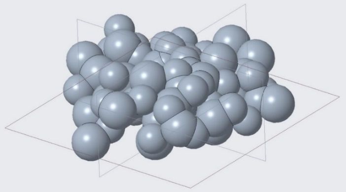
Materials 2019, 12, 1301 10 of 13
Materials
Materials2019,
2019,12,
12,xxFOR
FORPEER
PEERREVIEW
REVIEW 10
10ofof13
13
Figure 14.Example
Figure14. Exampleofofaacross-cut
cross-cutsection
sectionofofthe
thesample
samplefoam.
foam.
Figure
Figure15.
Figure 15.Example
15. Exampleof
Example ofthe
of thenominal
the nominalcross-section
nominal cross-sectioncorresponding
cross-section totothe
correspondingto
corresponding the actual
theactual cross-cut
actualcross-cut section.
cross-cutsection.
section.
Table 2.
Table Nominal vs
vs average actual
actual circle diameter
diameter (ordered by size) and corresponding mismatches.
Table2.2.Nominal
Nominal vsaverage
average actualcircle
circle diameter(ordered
(orderedby
bysize)
size)and
andcorresponding
correspondingmismatches.
mismatches.
Nominal (mm)(mm)
Nominal
Nominal (mm) Actual
Actual(mm)
Actual (mm)
(mm) MismatchMismatch
Mismatch (%)(%)
(%)
0.46 0.46
0.46 0.51
0.51
0.51 8.9
8.9 8.9
1.81 1.81
1.81 1.97
1.97
1.97 8.8 8.8
8.8
2.62 2.71 3.2
2.62
2.62 2.71
2.71 3.2
3.2 1.4
2.87 2.91
2.88 2.87
2.87 2.91
2.91
2.98 1.4
1.4 3.6
2.91 2.88
2.88 2.98
2.98
3.07 3.6
3.6 5.3
3.51 2.91
2.91 3.79
3.07
3.07 5.3 8.1
5.3
4.13 3.51
3.51 4.12
3.79
3.79 8.1 0.0
8.1
4.37 4.45 1.8
4.13
4.13 4.12
4.12 0.0
0.0 1.4
4.38 4.32
4.81 4.37
4.37 4.45
4.45
4.92 1.8
1.8 2.2
6.00 4.38
4.38 4.32
4.32
6.17 1.4
1.4 2.8
4.81
4.81 4.92
4.92 2.2
2.2
6.00 6.17
6.00of 4.0% resulted,
6.17 2.8
An average absolute mismatch and two reasons2.8
can be inferred for conditions of
mismatch above 5%. At first, the resolution of the printing machine is a factor in the roundness error
An average absolute mismatch ofof4.0% resulted, and two reasons can bebeinferred for
forconditions
when An average
small absolute
circles, (i.e., at mismatch
the poles of a4.0% resulted,
sphere, for a and
circletwo reasons
of 0.46 mmcannominalinferred
diameter) conditions
must be
ofofmismatch
mismatch above
above 5%.
5%. At
At first,
first, the
theresolution
resolution of
ofthe
the printing
printing machine
machine is
isaafactor
factorin
inthe
the roundness
roundness
drawn (Figure 16). Moreover, high percentage mismatch could result as a consequence of wall collapse,
error
errorwhen
whensmall
smallcircles,
circles,(i.e.,
(i.e.,atatthe
thepoles
polesofofaasphere,
sphere,for
foraacircle
circleofof0.46
0.46mm
mmnominal
nominaldiameter)
diameter)must
must
be
bedrawn
drawn(Figure
(Figure16).
16).Moreover,
Moreover,high highpercentage
percentagemismatch
mismatchcould couldresult
resultasasaaconsequence
consequenceofofwallwallMaterials 2019, 12, 1301 11 of 13
Materials
Materials 2019,
2019, 12,
12, xx FOR
FOR PEER
PEER REVIEW
REVIEW 11
11 of
of 13
13
collapse, in fact,ofa major
in fact, a region regiondefect
of major
was defect
found was found
between thebetween theofinterfaces
interfaces pores withofnominal
pores with nominal
diameters of
diameters
1.81 of 1.81
and 3.51 and 3.5117),
mm (Figure mm (Figure
where 17),
wall where wall
thickness thickness
of 0.283 mm wasof set
0.283
in mm was setOn
the model. in the
the basis
model.
of
On
this,the basis
it may beofassumed
this, it may be constraint
that the assumed that
giventhetoconstraint given
wall thickness into
thewall thickness
design in the
algorithm of adesign
metal
algorithm
foam, mustofbe a metal
shiftedfoam,
from must
0.190 be
mmshifted from
to 0.300 mm 0.190 mm to 0.300 mm at least.
at least.
Figure
Figure 16.
16. Detail
Detail of
Detail of roundness
of roundness error
roundness error for
for the
the circle
circle of
of 0.46
0.46 mm
mm nominal
nominal diameter.
diameter.
diameter.
Figure
Figure 17.
17. Detail
Detail of
of collapse
collapse at
at the
the interface
interface between
between pores,
pores, nominal
nominal geometry
geometry is
is superimposed.
superimposed.
For
For the
the final
final purpose
purpose ofof checking
checking thethe fraction
fraction density,
density, weighing
weighing has
has been
been performed
performed andand the
the
density has been measured via the the Archimede
Archimede method.
method. An average weight of 52.786 g resulted; and
given a reference full
full density
density of
of 7.9 g/cm333, an average volume
7.9 g/cm volume of
of 6681
6681 mm
3
mm33 resulted, thus yielding to
aa 1.5%
1.5% error
error with
with respect
respect to
to the
the nominal
nominal model. The mismatch
model. The mismatch isis thought
thought to
to be
be affected
affected by
by aa small
small
quantity of trapped powder inside the specimen and
of trapped powder inside the specimen and a minor a minor geometric
geometric internal
internal error.
error.
4. Conclusions
4. Conclusions
In this
In this paper,
paper, an
an approach
approach to to design
design and
and build
build random
random foam
foam structures
structures with
with interconnected
interconnected
porosity has been presented. The strategy has been optimized for additive manufacturing
porosity has been presented. The strategy has been optimized for additive manufacturing via via laser
laser
powder bed fusion. For this purpose, several rules have been proposed. Namely, at the
powder bed fusion. For this purpose, several rules have been proposed. Namely, at the design stage, design stage,
aa general
general algorithm
algorithm has
has been
been developed
developed and
and tested
tested to
to model
model aa random
random foamfoam structure
structure using
using technical
technical
and manufacturing
and manufacturing constraints
constraints such
such as
as the
the range
range of
of the
the pore
pore size,
size, the
the wall
wall thickness, and the
thickness, and the aimed
aimed
fractional density. The latter depends on the specific application of the
fractional density. The latter depends on the specific application of the foam. foam.
In this phase, a combination of constrained Delaunay triangulations and the approach of Pauly
has been implemented to reduce the number of modelling points, and therefore the total size of the
STL file has benefited.Materials 2019, 12, 1301 12 of 13
In this phase, a combination of constrained Delaunay triangulations and the approach of Pauly
has been implemented to reduce the number of modelling points, and therefore the total size of the
STL file has benefited.
To test the approach, a steel cylindrical random foam has been designed and built. Good agreement
with the nominal model source file has been achieved, with minor errors of approximately 4.0%,
on average, for circle diameter. Crucial findings have been drawn to update the algorithm for model
generation, nevertheless, the intended volume, hence the intended density, has been matched in
this research with an overall 1.5% mismatch. This approach of designing random pore distributions
within a given bulk volume can be used to model any complex structure where inner interconnected
porosity is required in the form of random foam for the purpose of lightening the structure. A check of
manufacturability is the preliminary step before developing a structured experimental plan to further
investigate the impact of pore distribution on the mechanical properties.
Author Contributions: Conceptualization, N.C., S.L.C., F.C. and V.A.; methodology, N.C. and S.L.C.; software,
N.C. and S.L.C.; validation, F.C. and V.A.; formal analysis, N.C., S.L.C., F.C., and V.A.; investigation, N.C.,
S.L.C., F.C., and V.A.; resources, F.C. and V.A.; data curation, N.C., S.L.C., F.C., and V.A.; writing—original draft
preparation, N.C. and V.A.; writing—review and editing, S.L.C. and F.C.; visualization, N.C., S.L.C., F.C., and V.A.;
supervision, S.L.C. and F.C.
Funding: This research received no external funding.
Acknowledgments: Authors are thankful to AITeM-PromozioneL@ser for supporting the research.
Conflicts of Interest: The authors declare no conflict of interest.
References
1. Khoda, A.K.; Ozbolat, I.T.; Koc, B. Designing heterogeneous porous tissue scaffolds for additive manufacturing
processes. Comput. Aided Des. 2013, 45, 1507–1523. [CrossRef]
2. Emmelmann, C.; Sander, P.; Kranz, J.; Wycisk, E. Laser additive manufacturing and bionics: Redefining
lightweight design. Phys. Procedia 2011, 12, 364–368. [CrossRef]
3. Seo, J.; Lee, K.; Shim, D. Effects of process parameters on properties of porous foams formed by laser-assisted
melting of steel powder (AISI P21)/foaming agent (ZrH2) mixture. Opt. Laser Technol. 2018, 98, 326–338.
[CrossRef]
4. Caiazzo, F.; Campanelli, S.; Cardaropoli, F.; Contuzzi, N.; Sergi, V.; Ludovico, A. Manufacturing and
characterization of similar to foam steel components processed through selective laser melting. Int. J. Adv.
Manuf. Technol. 2017, 92, 2121–2130. [CrossRef]
5. Rosen, D. Computer-aided design for Additive Manufacturing of cellular structures. Comput. Aided Des.
Appl. 2007, 4, 585–594. [CrossRef]
6. Usera, D.; Alfieri, V.; Caiazzo, F.; Argenio, P.; Corrado, G.; Ares, E. Redesign and manufacturing of a
metal towing hook via laser additive manufacturing with powder bed. Procedia Manuf. 2017, 13, 825–832.
[CrossRef]
7. Syam, W.; Jianwei, W.; Zhao, B.; Maskery, I.; Elmadih, W.; Leach, R. Design and analysis of strut-based lattice
structures for vibration isolation. Precis. Eng. 2018, 52, 494–506. [CrossRef]
8. Caiazzo, F.; Cardaropoli, F.; Alfieri, V.; Sergi, V.; Cuccaro, L. Experimental analysis of Selective Laser Melting
process for Ti-6Al-4V turbine blade manufacturing. In Proceedings of the XIX International Symposium on
High-Power Laser Systems and Applications 2012, Istanbul, Turkey, 10–14 September 2012.
9. Xu, S.; Shen, J.; Zhou, S.; Huang, X.; Xie, Y. Design of lattice structures with controlled anisotropy. Mater. Des.
2016, 93, 443–447. [CrossRef]
10. Tan, P.; Tong, L.; Steven, G.P. Behaviour of 3D orthogonal woven CFRP composites, part II: FEA and analytical
modeling approaches. Compos. Part A Appl. Sci. Manuf. 2000, 31, 273–281. [CrossRef]
11. Betts, C. Benefits of metal foams and developments in modelling techniques to assess their materials
behaviour: A review. Mater. Sci. Technol. 2012, 28, 129–143. [CrossRef]
12. Chougrani, L.; Pernot, J.; Véron, P.; Abed, S. Lattice structure lightweight triangulation for Additive
Manufacturing. Comput. Aided Des. 2017, 90, 95–104. [CrossRef]Materials 2019, 12, 1301 13 of 13
13. Young, P.; West, T.B.; Coward, S.; Notarberardino, B.; Walker, B.; Abdul-Aziz, A. An efficient approach to
converting three-dimensional image data into highly accurate computational models. Philos. Trans. R. Soc. A
2008, 366, 3155–3173. [CrossRef] [PubMed]
14. Chew, L. Constrained Delaunay Triangulations. Algorithmica 1989, 4, 97–108. [CrossRef]
15. Yu, C.; Eifert, H.; Banhart, J.; Baumeister, J. Metal foaming by a powder metallurgy method: Production,
properties and applications. Mater. Res. Innov. 1998, 2, 181–188. [CrossRef]
16. Shim, J.; Byun, J. Production processes of porous metals and their applications. Korean J. Mater. Res. 2015, 25,
155–164. [CrossRef]
17. Ikeda, T.; Aoki, T.; Nakajima, H. Fabrication of lotus-type porous stainless steel by continuous zone melting
technique and mechanical property. Metall. Mater. Trans. A Phys. Metall. Mater. Sci. 2005, 36, 77–86.
[CrossRef]
18. Caiazzo, F.; Alfieri, V. Laser-aided Directed Energy Deposition of steel powder over flat surfaces and edges.
Materials 2018, 11, 435. [CrossRef] [PubMed]
19. Calignano, F. Design optimization of supports for overhanging structures in aluminum and titanium alloys
by selective laser melting. Mater. Des. 2014, 64, 203–213. [CrossRef]
20. Szilvśi-Nagy, M.; Mátyási, G. Analysis of STL files. Math. Comput. Model. 2003, 38, 945–960. [CrossRef]
21. Pauly, M.; Gross, M.; Kobbelt, L. Efficient simplification of point-sampled surfaces. In Proceedings of the
IEEE Visualization 2002, Boston, MA, USA, 28–29 October 2002.
22. Koc, B.; Ma, Y.; Lee, Y. Smoothing STL files by Max-Fit biarc curves for Rapid Prototyping. Rapid Prototyp. J.
2000, 6, 186–203. [CrossRef]
23. Caiazzo, F.; Alfieri, V.; Corrado, G.; Argenio, P. Laser powder-bed fusion of Inconel 718 to manufacture
turbine blades. Int. J. Adv. Manuf. Technol. 2017, 93, 4023–4031. [CrossRef]
24. Riazi, H.; Ashrafizadeh, F.; Hosseini, S.; Ghomashchi, R.; Liu, R. Characterization of simultaneous aged and
plasma nitrided 17-4 PH stainless steel. Mater. Charact. 2017, 133, 33–43. [CrossRef]
© 2019 by the authors. Licensee MDPI, Basel, Switzerland. This article is an open access
article distributed under the terms and conditions of the Creative Commons Attribution
(CC BY) license (http://creativecommons.org/licenses/by/4.0/).You can also read


