DESIGN GUIDELINES FOR ABC COLUMN-TO-DRILLED-SHAFT FOUNDATION CONNECTIONS IN HIGH SEISMIC ZONES
←
→
Page content transcription
If your browser does not render page correctly, please read the page content below
DESIGN GUIDELINES FOR ABC COLUMN-TO-DRILLED-SHAFT
  FOUNDATION CONNECTIONS IN HIGH SEISMIC ZONES

                      Quarterly Progress Report
                  For the period ending May 31, 2021

                             Submitted by:
                           PI: Marc Eberhard
                          Co-PI: John Stanton
                   Research Assistant: Michelle Chang

     Affiliation: Department of Civil and Environmental Engineering
                        University of Washington

                              Submitted to:
                                ABC-UTC
                     Florida International University
                                Miami, FL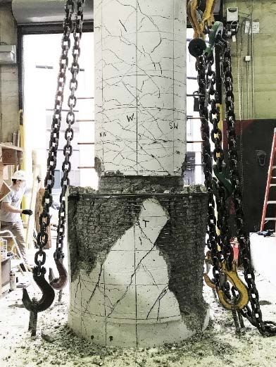
Background and Introduction
Precast columns have the potential to be very cost- and time-efficient for ABC, but they must be
connected effectively to the foundation, particularly in regions of moderate or high seismicity.
Most of the relevant research on column-to-foundation connections has been conducted for
spread footings, but drilled shafts (most commonly with a diameter larger than that of the
column) are preferred in many applications. Little research has been performed on the seismic
performance of connections between precast columns and enlarged drilled shafts.
Discussion with the Washington State Department of Transportation (WSDOT) and California
Department of Transportation (Caltrans) indicate that drilled shaft foundations are being used
with increasing frequency for bridges. Drilled shafts are often needed to support a bridge when
the soil conditions, or limited space, make it difficult or impossible to use spread footings. Speed
and simplicity of construction, which are essential to ABC, require adequate construction
tolerances, and these are most easily achieved if the shaft diameter is larger than that of the
column.

   Problem Statement
The current AASHTO ABC design recommendations for shafts are based on the results of cast-
in-place column behavior and a single cyclic test of a column-to-shaft subassembly. This
research uses experimental data from a past study (Fig. 1) and data from a PEER-funded study to
calibrate strut-and-tie and/or finite-element models of connections between precast columns and
cast-in-place drilled shafts. The calibrated models will be used in a parametric study, whose
results will make it possible to develop design recommendations for such connections.

                  Figure 1. Tran Tests of Connection Between Precast Column
                                  and Enlarged Drilled Shaft

   Objectives and Research Approach
UW researchers will develop guidelines for the design of ABC connections between precast
columns and enlarged, cast-in-place drilled shafts in seismic regions. These guidelines will be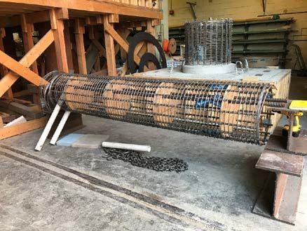
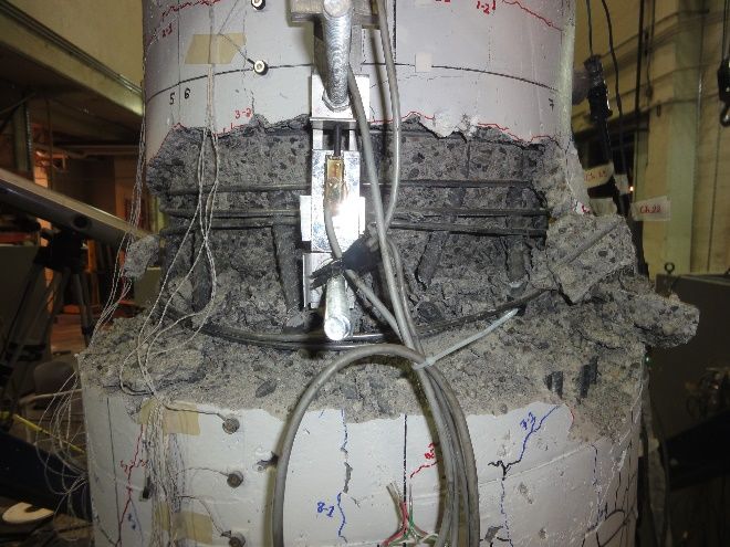
based on the results of three tests conducted previously (Tran 2015), and one additional new test
conducted with PEER funding. The team will perform a parametric study using strut-and-tie
models and/or finite-element models, which will have been calibrated with the test results, to
consider a wider range of column and shaft properties.

   Description of Research Project Tasks
The following is a description of tasks carried out to date.
   PEER –Funded Research.

The PEER-funded research has been completed.

An additional test of a column-to-drilled shaft
connection was performed with the support of the
Pacific Earthquake Engineering Research center
(PEER). These tests were delayed by laboratory delays
due to Covid-19, but the laboratory is now open for
research. During the Summer of 2020, graduate student
researcher Michelle Chang constructed some of the
formwork and reinforcement cages for her specimen.              Figure 2. Photo of Shaft and Base
Figures 2, 3 and 4 shows photos of the specimen under                     Reinforcement
construction.

 Figure 3. Photo of Shaft Reinforcement           Figure 4. Photo of Column Reinforcement Cage
 and Cast Base

During Autumn of 2020, the specimen construction was completed, and the column of the test
specimen was subjected to a constant axial load and cyclic, lateral displacements. Figure 5 shows
Ms. Chang in front of her specimen at the end of the test. Figure 6 shows the damage to the
column-to-drilled-shaft connection. The failure mode consisted of bursting of the top of the
drilled shaft near the bottom of the columns.
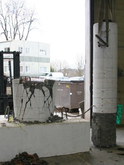
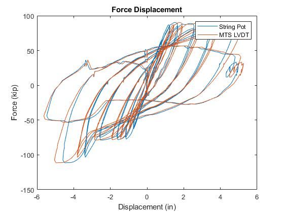
Figure 5. Photo of Connection Specimen              Figure 6. Photo of Damage to Drilled-
 and End of Testing                                  Shaft Connection

Task 1 – Analysis of Data from Tran Tests and New Test.

Task 1 has been completed.

All of the data collected by Tran (2015) was preserved, but it was necessary to re-analyze the
data, so that the data processing methodology for the previous tests will be consistent with that
used for the new, PEER-funded tests. This analysis also made it possible to design the new test
specimens to so that they would be most useful in developing new design recommendations.

Researcher Michelle Chang reproduced the calculations performed by Hung Tran for specimens
DS-1, DS-2, DS-3, and in a few cases, she corrected errors in the earlier data analyses. These
analyses were used to select an additional specimen to test (DS-4). In addition, the research team
identified an additional test that was performed recently at the University of California, San
Diego. The additional data will be integrated into Michelle Chang’s analysis framework.

During the first quarter of 2021, Ms. Chang analyzed the measured data from test DS-4, so that
the research team can understand its behavior and compare the performance of the most-recently
tests specimen with those tested earlier by others.

Figure 7 shows the measured overall force-displacement response for specimen DS-4. The
specimen developed the full column flexural strength at a lateral displacement of about 1 inch,
and it maintained its peak resistance until a top displacement of approximately 4-5 inches.
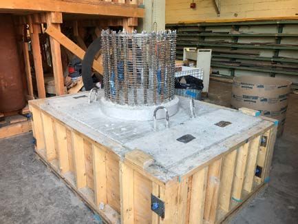
Figure 7. Overall Force-Displacement Response for Specimen DS-4.

The proportioning of the transverse reinforcement in the drilled shaft is a critical design
consideration, because this reinforcement resists the splitting failure shown in Fig. 6. Figure 8
shows the vertical distribution (0 in. corresponds to column-shaft interface) of measured strains
in the shaft transverse reinforcement for three levels of drift ratio (1%, 2% and 3%). Separate
curves are shown for the North-Face Tension (NT), North-Face Compression (NC), South-Face
Tension (ST), South-Face Compression (SC) and East-Face (E).

              Figure 8. Vertical Distributions of Transverse Reinforcement Strains.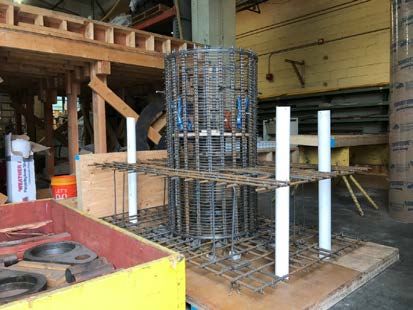
Figure 8 supports the following conclusions:

   •   The distribution of strains over the height of the drilled shaft is approximately parabolic.
   •   The transverse reinforcement at the top of the shaft yielded (~0.0022) at a drift ratio near
       2%. The strains at a drift ratio of 4% were roughly double those at a drift ratio of 2%.
   •   At larger drift ratios (above 1% or so), the transverse reinforcement strains tended to be
       largest on the compression side, of intermediate magnitude on the “unloaded” East side,
       and smallest on the tension side.

During Spring 2021, the experimental data from the recent DS-4 test was compared with the data
available from previous DS-1, DS-2 and DS-3 tests (Huang 2015). Figure 8 shows photographs
of the damage of the four specimens at the end of testing. The damage to specimens DS-1 and
DS-3 consisted of flexural damage at the base of the column, which is the desired behavior. In
contrast, DS-2 and DS-4 failed in the shaft, an undesirable failure mode.

                             DS-1                                       DS-2

                             DS-3                                       DS-4
                 Figure 9. Photographs of Specimen Damage at End of Testing.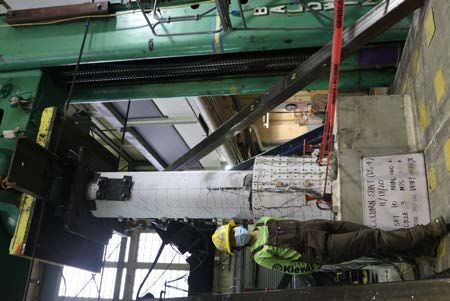
Figure 10 shows how the variation of the maximum transverse strain in the shaft reinforcement
varies with the imposed drift ratio for the four DS specimens. The transverse strains increase
much more rapidly in DS-2 and DS-4 than in DS-1 and DS-3. These differences in measured
strains are consistent with observed damage in the four specimens.
                                                              -3
                                                         10
                                                 5

                                                                         DS-1
                                               4.5                       DS-2
                                                                         DS-3
                                                 4                       DS-4

                                               3.5
              Peak Transverse Strain (in/in)

                                                 3

                                               2.5

                                                 2

                                               1.5

                                                 1

                                               0.5

                                                 0
                                                     0             0.5          1   1.5   2      2.5      3   3.5   4   4.5   5
                                                                                              Drift (%)

       Figure 10. Variation of Strains in Shaft Transverse Reinforcement with Drift Ratio

   Task 2 – Development/Calibration of Analytical Models

90% of Task 2 has been completed.

A strut-and-tie models was developed and calibrated to be consistent with the observations and
data available from Tran (2015), the PEER-funded tests, and the results of four specimens tested
at the University of California, San Diego, C. Figure 11 shows the final form of two strut-and-tie
models that produces consistent results. The model on the left governs when shear forces are
relatively high compared to the bending forces. The model of the right governs when bending
forces govern the behavior.
Figure 11. Strut-and-Tie for Column-to-Shaft Connection

   Task 3 – Parametric Study

No progress has yet been made on this task. This task will be completed during the Summer of
2021.

The developed models will be used in a parametric study to evaluate the effects of key design
variables, including the depth of embedment of the precast column, the relative diameters of the
column and shaft, as well as the details of the longitudinal and transverse reinforcement.

   Task 4 – Development of Design Recommendations

No progress has yet been made on this task. This task will be completed during the Summer of
2021.

The results of the parametric study will be used to develop design recommendations that would
be suitable for practice. These recommendations will be reviewed by bridge engineers from
California and Washington states to verify that the form is appropriate.

   Expected Results and Specific Deliverables
The main deliverable will be a report that summarizes:
   •   Results of the parametric study,
   •   Calibrated models of the connection, and
•    Design recommendations.

   Schedule
Progress of tasks in this project is shown in the tables below.

 Item                                                 % Completed

 Percentage of Completion of this project to Date     80%

                                         Table 1. Schedule
         Research Task                   2020             2021
                                   M J J A S O N D J F M A M J J A S
 Task 1 – Analysis of New
 and Tran Test Data.
 Task 2 – Development of
 Analytical Models
 Task 3 – Parametric Study

 Task 4 – Development of
 Design Recommendations
                                Work Performed

                                Work to be Performed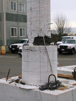
You can also read