Design Guidelines for Deployable Wind Turbines for Military Operational Energy Applications
←
→
Page content transcription
If your browser does not render page correctly, please read the page content below
Design Guidelines for Deployable
Wind Turbines for Military
Operational Energy Applications
Brian Naughton, Sandia National Laboratories
Tony Jimenez, Robert Preus, and Brent Summerville, National Renewable Energy
Laboratory
Brad Whipple, Dylan Reen, and Jake Gentle, Idaho National Laboratory
Eric Lang, University of Dayton Research Laboratory

November 2021
SAND2021-14581 R

 Sandia National Laboratories is a multimission laboratory
 managed and operated by National Technology and Engineering
 Solutions of Sandia, LLC, a wholly owned subsidiary of Honeywell
 International Inc., for the U.S. Department of Energy’s National
 Nuclear Security Administration under contract DE-NA0003525.

ACKNOWLEDGMENTS
The authors would like to thank the many reviewers of this document who provided their valuable time
and extensive knowledge gained from years of wind industry and military experience to improve the
information provided here. We aimed to capture and distill all that knowledge into a useful reference,
but we also recognize that there are areas to improve and expand, and hope for a continued dialogue
going forward.

 2
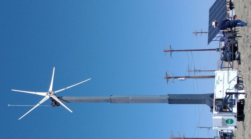
TABLE OF CONTENTS
1. Purpose and Overview ............................................................................................................................... 7
2. Deployable Wind Applications ................................................................................................................. 8
3. Overview of Military Mobile Electric Power Systems ........................................................................... 9
 3.1. Mobile Diesel Generators ................................................................................................................ 9
 3.2. Power Distribution and Control ..................................................................................................... 9
 3.3. Mobile Hybrid Power Systems ....................................................................................................... 9
4. Military and Industry Reference Standards and Specifications .......................................................... 11
 4.1. Environmental Conditions ............................................................................................................ 11
 4.2. Transportation ................................................................................................................................. 13
 4.3. Electrical Power Systems and Components ............................................................................... 13
 4.4. Wind Turbines................................................................................................................................. 14
5. Deployable Wind Turbine Design Guidelines ...................................................................................... 17
 5.1. Mission Planning ............................................................................................................................. 17
 5.2. Transportation Logistics ................................................................................................................ 19
 5.3. Installation and Removal ............................................................................................................... 19
 5.4. Operations and Maintenance ........................................................................................................ 20
 5.5. Power System Integration.............................................................................................................. 21
 5.6. Institutional Considerations .......................................................................................................... 21
Appendix A. Container Analysis ............................................................................................................ 22
Appendix B. Foundation Analysis ......................................................................................................... 27
Appendix C. Wind Resource Assessment and Siting .......................................................................... 34
 C.1. Global Wind Atlas .......................................................................................................................... 34
 C.2. Wind Turbine Siting ....................................................................................................................... 34
 C.3. Estimated Wind Energy Calculation ............................................................................................ 35
Appendix D. IEC Wind Turbine Standards .......................................................................................... 37
 D.1. Recommended Deviations From the IEC Standard ................................................................. 37
 D.2. Recommendations for Working Within the IEC Standard ...................................................... 37
Appendix E. Power System Integration Standards.............................................................................. 40
Appendix F. Military Reference Documents........................................................................................ 45
 F.1. Logistics and Transportation ........................................................................................................ 45
 F.2. Design and Manufacturing ............................................................................................................ 47
 F.3. Installation and Operations ........................................................................................................... 48
 F.4. Electrical Components ................................................................................................................... 49
Appendix G. Military Hybrid Mobile Power System Programs ......................................................... 51
References ......................................................................................................................................................... 54

 3
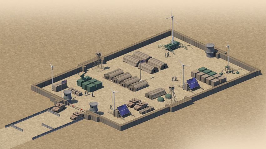
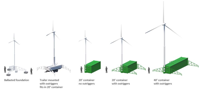
LIST OF FIGURES
Figure 1. Rendering of various deployable wind turbine concepts at a forward operating base ........... 7
Figure 2. Average annual wind speed as a percent of global land and nearshore area, as well as height
 above ground .............................................................................................................................................18
Figure 3. Example wind turbine power curves for two different rotor sizes..........................................18
Figure 4. Northern Power Systems NPS 100C-24 with hub extenders (en.wind-turbine-models.com)
 .....................................................................................................................................................................22
Figure 5. Rated power versus rotor swept area ...........................................................................................23
Figure 6. Single-piece, monopole tower (left, Pika Energy turbine, NREL PIX 31470), segmented,
 guyed tower (center, Bergey Windpower turbine, NREL PIX 16742), and telescoping tower
 (Uprise Energy turbine, Idaho National Lab) .......................................................................................24
Figure 7. HCI Energy hybrid cube ................................................................................................................25
Figure 8. Uprise Energy system in trailer mode (photo from Idaho National Lab) ..............................25
Figure 9. DARPS system from Bergey Windpower ...................................................................................26
Figure 10. NPS 100-24 deployed on Necker Island ...................................................................................26
Figure 11. Overturning moments and resistance to overturning..............................................................27
Figure 12. HCI Hybrid Cube analysis ...........................................................................................................27
Figure 13. Uprise Energy analysis..................................................................................................................28
Figure 14. Bergey Windpower analysis .........................................................................................................28
Figure 15. Projected blade area versus rotor diameter ...............................................................................29
Figure 16. Summary of foundation options explored. ...............................................................................30
Figure 17. Overturning summary graph .......................................................................................................31
Figure 18. Sliding summary graph .................................................................................................................31
Figure 19. AWE ...............................................................................................................................................32
Figure 20. TMS Device Roles (TMS Appendix A.6) ..................................................................................41
Figure 21. Schematic diagram of the source device role (TMS B.1.1) .....................................................42

 4
LIST OF TABLES
Table 1. Summary of climatic conditions and daily cycles of temperature, solar radiation, and relative
 humidity from MIL-STD-810H..............................................................................................................12
Table 2. Annual energy production of two different size rotors operating in two different average
 wind speeds corresponding to two different heights ...........................................................................19
Table 3. Standard shipping container dimensions [9].................................................................................22
Table 4. Maximum rotor size per container.................................................................................................23
Table 5. Maximum tower height options per container .............................................................................24
Table 6. Data Table for foundation analysis ................................................................................................32
Table 7. Normal Environmental Conditions ...............................................................................................38
Table 8. Extreme Environmental Conditions .............................................................................................38
Table 9. Miscellaneous Environmental Conditions ....................................................................................39

 5
NOMENCLATURE
AC alternating current
AHJ authority having jurisdiction
AMMPS Advanced Medium Mobile Power Source
ANSI American National Standards Institute
ATP Army Techniques Publication
AWEA American Wind Energy Association
COTS commercial off-the-shelf
D3T Defense and Disaster Deployable Turbine
DARPS Deployable Advanced Renewable Power System
DC direct current
DoD U.S. Department of Defense
DOE U.S. Department of Energy
DPGDS Deployable Power Generation & Distribution System
D-REPS Deployable–Renewable Energy Power System
E2S2 Expeditionary Energy & Sustainment Systems
FOB forward operating base
GREENS Ground Renewable Expeditionary Energy Network System
IEC International Electrotechnical Commission
IEEE Institute of Electrical and Electronics Engineers
IPDISE Improved Power Distribution Illumination System Electrical
ISO International Organization for Standardization
kW kilowatt
LAMPS Large Advanced Mobile Power Sources
MEMS microgrid energy management system
MEPS Mobile Electric Power Systems
MOS military occupational specialty
NATO North Atlantic Treaty Organization
NEC National Electrical Code
SEPS Small Expeditionary Power Systems
SPACES Solar Portable Alternative Communications Energy System
SWT small wind turbine
SWCC Small Wind Certification Council
TMS Tactical Microgrid Standard
TOP Test Operating Procedure
TQG Tactical Quiet Generator
USMC United States Marine Corps

 6
1. PURPOSE AND OVERVIEW
This document aims to provide guidance on the design and operation of deployable wind systems that
provide maximum value to missions in defense and disaster relief. Common characteristics of these
missions are shorter planning and execution time horizons and a global scope of potential locations.
Compared to conventional wind turbine applications, defense and disaster response applications place a
premium on rapid shipping and installation, short-duration operation (days to months), and quick
teardown upon mission completion. Furthermore, defense and disaster response applications are less
concerned with cost of energy than conventional wind turbine applications. These factors impart design
drivers that depart from the features found in conventional distributed wind turbines, thus necessitating
unique design guidance. The supporting information for this guidance comes from available relevant
references, technical analyses, and input from industry and military stakeholders. This document is not
intended to be a comprehensive, prescriptive design specification. This document is intended to serve as
a written record of an ongoing discussion of stakeholders about the best currently available design
guidance for deployable wind turbines to help facilitate the effective development and acquisition of
technology solutions to support mission success.

The document is generally organized to provide high-level, focused guidance in the main body, with
more extensive supporting details available in the referenced appendices. Section 2 begins with a brief
qualitative description of the design guidelines being considered for the deployable wind turbines.
Section 3 provides an overview of the characteristics of the mobile power systems commonly used in
U.S. military missions. Section 4 covers current military and industry standards and specifications that
are relevant to a deployable wind turbine design. Section 5 presents the deployable turbine design
guidelines for the application cases.

 Figure 1. Rendering of various deployable wind turbine concepts at a forward operating base

 7
2. DEPLOYABLE WIND APPLICATIONS
The report Market Opportunities for Deployable Wind Systems for Defense and Disaster Response [1] and a
subsequent assessment of currently available commercial wind turbines identified three proposed size
ranges for deployable wind systems to address three defense and disaster response applications with
unique design requirements. One system is for individual or small teams, whereas the other two are for
contingency bases of different scales. This structure was adopted for the design guidelines in this
document with the general characteristics of each as follows:

Wind system for individual, small team, or small unmanned station
 • Highly mobile, very quick setup and takedown (minutes)
 • Lightweight, packable by person or small trailer
 • Generally less than 3-kilowatt (kW) power
 • Primary application is charging batteries and small electronics (DC)
 • Installed and operated at the individual operator skill level with common tools

Wind system for contingency base (smaller)
 • Support a portion of the loads of a company-sized element (~300 personnel) with deployments
 for weeks to months
 • Setup and takedown in hours
 • Physical dimensions and weight driven by organic logistics capabilities, common shipping
 containers
 • Generally, single unit maximum rated power is 10–20 kW (estimated)
 • Multiple units deployed and integrated into microgrid with other generation and storage
 • Primary application is general operational loads using AC
 • Installed and operated at the individual operator and unit skill level with common tools

Wind system for contingency base (larger)
 • Support a portion of the loads of a battalion or brigade-sized (~1,000–3,000 personnel) element
 with deployments for months to more than a year
 • Setup and takedown in hours to days
 • Physical dimensions and weight driven by logistics capabilities, possibly including specialized
 equipment
 • Generally, single unit maximum rated power is up to ~100 kW (estimated)
 • Multiple units deployed and integrated into microgrid with other generation and storage
 • Primary application is general operational loads using AC
 • Installed and operated at the specialty/organizational skill level

 8
3. OVERVIEW OF MILITARY MOBILE ELECTRIC POWER SYSTEMS
The development, procurement, and sustainment of mobile electric power systems for the U.S. military
is primarily managed by the U.S. Army Office of the Project Manager Expeditionary Energy &
Sustainment Systems (E2S2). The current structure of that office includes two subprograms for Small
Expeditionary Power Systems (SEPS) and Mobile Electric Power Systems (MEPS). The building blocks
of these mobile power systems are diesel generators ranging from 2 kW up to over 200 kW, generally
providing spot power generation in a non-networked configuration. These program offices also
continue to develop power system distribution and control products and alternative generation sources
to augment the diesel spot generators. Other nonstandard and larger power generators are also used
across the services.

3.1. Mobile Diesel Generators
The vast majority of military contingency operations rely on diesel-powered generators to provide
electricity to mission-related loads. As a result, logistics capabilities and requirements, operator training
and skills, and typical equipment for operational energy systems are primarily driven by these generators.
This is an important consideration for designing a deployable wind system that is compatible not only
technically, but logistically, with existing power generation systems.
Small Expeditionary Power Sources
The E2S2 Product Director Small Expeditionary Power Sources (PD SEPS) provides warfighters with
expeditionary energy solutions that are less than 5 kilowatts. Current products are 2-kW and 3-kW
tactical generators, with newer technologies currently in development to support platoon-scale power
needs. There are also early-stage technical products to provide soldier-level power below 1 kW.
Advanced Medium Mobile Power Source
The Advanced Medium Mobile Power Source (AMMPS) line of generators from 5 kW to 60 kW are
replacing the prior line of military Tactical Quiet Generators (TQGs), although both are currently in
operation. AMMPS generators can be skid mounted, trailer mounted, or configured in a microgrid.

Large Diesel Power Systems
The largest mobile electric power systems start at 100 kW and generally include more advanced
distribution systems to power larger bases. The Large Advanced Mobile Power Sources (LAMPS)
generators are 100 kW and 200 kW in size. The Deployable Power Generation & Distribution System
(DPGDS) is the largest mobile power system at 840 kW as a prime power unit (as compared to smaller
tactical power units) to be used as part of a distribution system with transformers and lines to deliver
power to loads.

3.2. Power Distribution and Control
The Improved Power Distribution Illumination System Electrical (IPDISE) system is an updated
product that allows personnel to effectively distribute power between power generation and powered
equipment while optimizing generator usage. The IPDISE system can network older generators and the
newer LAMPS and AMMPS generators, facilitating operational fielded microgrids.

3.3. Mobile Hybrid Power Systems
The military has also developed mobile hybrid power system products to varying levels of maturity over
the years, most of them not widely fielded for various reasons. Hybrid power systems include more than
one generation or storage technology and may include diesel generators. A brief summary of a selection

 9
of these programs can be found in Appendix A, some of which have included alternative energy
generators, including wind turbines. These programs can offer some insight into the benefits and
shortcomings of prior hybrid designs.

 10
4. MILITARY AND INDUSTRY REFERENCE STANDARDS AND
 SPECIFICATIONS
Existing military and industry standards and specifications, ranging from general to wind system-
specific, provide useful and important foundational guidance applicable to deployable wind turbine
systems. Brief summaries of the most relevant references are included in this section. Additional
references to military and industry specifications and standards are included in the appendices.

4.1. Environmental Conditions
Military operations require reliable and rugged equipment to work in austere environments. The U.S.
Department of Defense (DoD) has set forth standards and methods for testing equipment for a variety
of global conditions. Although it may not be necessary to strictly adhere to these standards, it is
important to recognize these standards do provide insight into the expectations of military equipment
generally. When establishing the desired environmental operating range, it is important to consider the
potential unintended design and performance consequences of requiring too wide of a range.
Requirements for extreme weather or temperature operation can lead to expensive, heavy, complex
solutions with degraded performance due to the added material or subsystems. In addition to the
specific references covered in this section, the U.S. Army Test and Evaluation Command publishes Test
Operations Procedures (TOPs) for a variety of equipment. Although there is not yet a specific TOP for
wind turbines, there is one for photovoltaic systems, which is described along with other specific
standards in Appendix F.

MIL-STD-810 Environmental Engineering Considerations and Laboratory Tests
The MIL-STD-810 standard addresses how products are tested for environmental survivability [2].
When products are marketed as “military grade” or “mil spec,” they are often in reference to the
products passing portions of the testing procedures outlined in MIL-STD-810. Currently, some solar
panel products are marketed and sold as MIL-STD-810-approved. Revisions of this document are
updated periodically and indicated with an incremental letter suffix. At the time of writing this
document, the latest version is MIL-STD-810H dated 31 January 2019.

Section three of MIL-STD-810H describes the five “Climactic Design Types” that characterize the
ambient environmental conditions that DoD equipment may encounter (Table 1). Note that the
temperature range of transportation and storage is wider than the ambient conditions temperature range.
These Climactic Design Types not only characterize the conditions under which equipment should
function while installed, but also characterize the shipping and transport conditions. At a minimum,
deployable turbines should be designed to function (or at least not suffer damage while not operating) in
the Basic and Hot Climate Design Types. Combined, these two Climate Design Types define a
temperature range of −32°C to +49°C of operational conditions. This temperature range is most
comparable to the “Extreme Temperature Range” for wind turbines defined by the International
Electrotechnical Commission (IEC) as at least −20°C to +50°C. This encompasses the vast majority of
land surface areas in the world.

Beyond the items characterized in Table 1, both the IEC Standard and MIL-STD-810H discuss (in a
qualitative sense) other environmental conditions, listed below, that may influence deployable turbine
design:

 11
• Temperature • Chemically active substances
 • Humidity • Mechanically active particles (sand, dust)
 • Air density • Lightning
 • Solar radiation • Earthquake
 • Rain, hail, snow, and ice • Marine environment – corrosion.

Table 1. Summary of climatic conditions and daily cycles of temperature, solar radiation, and relative
humidity from MIL-STD-810H.
 Storage and Transit
 Operational Conditions Conditions
 Induced
 Ambient Air Air
 Temperature Temperature
 °C (°F) Solar °C (F) Natural
 Radiation Ambient Induced Environment
 Climatic W/m² Relative Relative Exposure
 Design Daily Daily (Btu/ft2/ Humidity Daily Daily Humidity Testing
 Type Daily Cycle Low High hr) %RH Low High %RH °C (F)
 32 49 0 to 1,120 33 71 32 to 49 (90 to
 Hot Dry (A1) 8 to 3 7 to 1
 (90) (120) (0 to 355) (91) (160) 120)
 Hot
 Hot Humid 31 41 0 to 1,080 33 71
 88 to 59 80 to 14 Coastal Desert
 (B3) (88) (105) (0 to 343) (91) (160)
 Basic Hot 30 43 0 to 1,120 30 63
 44 to 14 44 to 5
 (A2) (86) (110) (0 to 355) (86) (145) 0 to 43
 Intermediate 28 39 0 to 1,020 28 58 (32 to 110)
 78 to 43 See note 1
 (A3) (82) (102) (0 to 323) (82) (136)
 Variable
 High 26 35 0 to 970 30 63
 100 to 74 75 to 19
 Humidity (78) (95) (0 to 307) (86) (145)
 (B2) Humid
 Constant Tropics
 Basic Nearly Nearly
 High
 Constant Negligible 95 to 100 Constant 95 to 100
 Humidity
 24 (75) 27 (80)
 (B1)
 Tending Tending
 Mild Cold -19 -6 -21 -10
 Negligible toward toward
 (C0) (-2) (21) (-6) (14)
 saturation saturation 0 to -32
 Tending Tending (32 to -25)
 Basic Cold -32 -21 -33 -25
 Negligible toward toward
 (C1) (-25) (-5) (-28) (-13)
 saturation saturation
 Tending Tending
 Cold -46 -37 -46 -37 -32 to -46 (-26
 Cold Negligible toward toward
 (C2) (-50) (-35) (-50) (-35) to 50)
 saturation saturation
 Tending Tending
 Severe Severe Cold -51
 -51 (-60) Negligible toward toward
 Cold (C3) (-60)
 saturation saturation < -46
 Extreme Tending Tending (< -50)
 Extreme -57
 Cold -57 (-70) Negligible toward toward
 Cold (-70)
 (C4) saturation saturation

1Relative humidity for the A3 storage condition vary too widely between different situations to be represented by a single set
of conditions.

 12
4.2. Transportation
The military has a variety of specifications covering logistical and safety considerations for the
transportation of equipment. It is critical to consider all of the components of a deployable wind system
when meeting transportation requirements. Items like batteries and permanent magnets have special
restrictions due to their potential impact to safe operations.

Army Container Operations ATP 4-12 (May 2013)
Army Techniques Publication (ATP) 4-12, Container Operations [3], is the Army’s doctrine for
container management during operations and ensures that unit equipment and supplies are delivered in a
timely and secure manner to the intended destination. To minimize intermodal logistics constraints, the
Army uses standard 20-foot International Organization for Standardization (ISO) steel containers to
move materiel. Although larger 40-foot ISO containers have been used in the past, DoD has removed
them from their inventory to simplify handling equipment. Commercial 40-foot containers may be used
to ship items to a primary logistics port, but the container-handling equipment at more forward
operating locations is limited to the 20-foot containers.

Army Cargo Specialists’ Handbook FM 55-17 (1999)
This Army field manual covers cargo handling specifications for intermodal transportation of material
[4]. Part 4 of the manual discusses air transport on common cargo handlers like the C-17 and C-130
aircraft. These platforms use a standardized pallet system named the 463L. The 463L pallet dimensions
are 108 inches by 88 inches by 2 1/4 inches. It weighs 337 pounds and has a total load capacity of
10,000 pounds, with a desired load capacity of 7,500 pounds.

Air Force Interservice Manual 24-204: Preparing Hazardous Materials for Military Air
Shipments (July 2018)
This Air Force document has requirements for transportation and shipping of hazardous material, via
military air shipment [5]. Specific to a wind turbine system may be the transportation of lithium batteries
and magnetized materials. This document includes guidelines on the number of allowed lithium
batteries, requirements on the segregation of lithium batteries, and other requirements. For magnetic
components, any package that has a magnetic field strength of more than 0.00525 gauss measured at 4.5
m (15 ft) from any surface of the package is forbidden on military aircraft. Additional details on lithium
batteries and magnetic materials from this specification can be found in Appendix F.

4.3. Electrical Power Systems and Components
A deployable wind turbine generator must comply with both military and industry standards to facilitate
safe operation and interoperability with other power system components. Microgrids are an especially
active area of development and implementation in commercial and military systems and the following
standards are among the most prominent references.

Tactical Microgrid Standard
The Tactical Microgrid Standards Consortium is a DoD and industry collaborative working to develop a
standard for military microgrids in contingency operations led by the U.S. Army Corps of Engineers.
The standard will address interoperability requirements for microgrids and their components, including
safety, protection and human factors, electrical interconnection, communications, controls, and
cybersecurity. The standard is planned for public release in 2021. More details on the draft standard are
provided in Appendix E.

 13
IEEE 1547-2018 Standard for Interconnecting Distributed Resources with Electric Power
Systems
The Institute of Electrical and Electronics Engineers (IEEE) 1547-2018 standard provides a uniform
standard for interconnection of distributed resources with electric power systems. It provides
requirements relevant to the performance, operation, testing, safety considerations, and maintenance of
the interconnection [6]. This standard is being adopted widely in commercial applications and the same
functionality may be leveraged in a military context in the absence of a specific military specification
such as the Tactical Microgrid Standard.

IEEE 2030 Standard for the Specification of Microgrid Controllers
A key element of microgrid operation is the microgrid energy management system (MEMS). It includes
the control functions that define the microgrid as a system that can manage itself, operate autonomously
or grid connected, and seamlessly connect to and disconnect from the main distribution grid for the
exchange of power and the supply of ancillary services. The scope of the IEEE 2030 standard is to
address the functions above the component control level associated with the proper operation of the
MEMS that are common to all microgrids, regardless of topology, configuration, or jurisdiction [7].

National Electrical Code (NEC): Installation and equipment standards
The NEC is a standard for the safe installation of electrical wiring and equipment in the United States
adopted by local states and municipalities and frequently referenced in DoD specifications. The local
authority having jurisdiction (AHJ) inspects for compliance with these standards. Wind systems are
installed to meet the NEC, the latest being NFPA 70: NEC 2020. The most relevant sections for wind
energy are:
 • 694 Wind Electric Systems
 • 705 Interconnected Electric Power Production
 • 706 Energy Storage Systems
 • 710 Stand Alone Systems
 • 712 Direct Current Microgrids

To pass inspection, the wind turbine electrical equipment, most notably the inverter, must have been
tested to meet:
 • IEEE 1547-2018 - IEEE Standard for Interconnection and Interoperability of Distributed
 Energy Resources with Associated Electric Power Systems Interfaces
 • UL 1741: Standard for Inverters, Converters, Controllers and Interconnection System
 Equipment for Use with Distributed Energy Resources
 • the communications requirements in IEEE 2030.5-2018 - IEEE Standard for Smart Energy
 Profile Application Protocol

4.4. Wind Turbines
IEC 61400-2, Part 2: Small wind turbines, Edition 3.0 the “IEC Standard,” is the main worldwide
standard for the design of small wind turbines. It is the basis for various national standards such as
American National Standards Institute/American Wind Energy Association (ANSI/AWEA) SWT-1
(2016) AWEA Small Wind Turbine Standard, “AWEA Standard.” Key related standards include: IEC
61400-11, Wind Turbines – Part 11: Acoustic Noise Measurement Techniques, IEC 61400-12-1, Wind
Energy Generation Systems – Part 12-1: Power Performance Measurements of Electricity Producing

 14
Wind Turbines, UL 6142: Standard for Safety for Small Wind Turbine Systems (2012), or for large
turbines UL 6141: Wind Turbines Permitting Entry of Personnel.

The IEC definition of “small wind turbine” is a turbine with a rotor swept area of up to 200 m2. This is
comparable to a 50–60-kW rated wind turbine. This top-end rated power may be less for a deployable
turbine because these turbines are likely to have an oversized rotor. Note that the U.S. Department of
Energy (DOE) defines a small turbine as a turbine of up to 100-kW rated power.

Deployable turbines for “large base” applications may fall into the informal “medium turbine” category.
The Small Wind Certification Council (SWCC) defines a medium turbine as one with a rotor swept area
between 200 m2 and 1,000 m2. DOE defines medium turbines as having a rated power greater than 100
kW up to 1.0 MW. This category is informal because there are no separate design standards for turbines
of this size range. Turbines in this size range are subject to the IEC 61400-1 standard for larger systems.

IEC 61400-2 provides a methodology for the design process, with an emphasis on the structural design,
to give reasonable assurance that the turbine will survive and function during its specified lifetime
(typically 20 years for commercial wind turbines). This begins with determining the environmental
conditions under which the turbine is expected to operate. For some categories of conditions, such as
wind regimes, the standard goes into some detail, characterizing four standard wind classes, I–IV, as well
as making provision for designers to characterize a nonstandard “S-class” wind regime. For other
conditions, such as dustiness, the discussion is much more qualitative, in essence stating that if the
turbine is going to be deployed in some extreme environment, take care to design for that environment.

Once the environmental conditions are determined, the IEC Standard provides a process to calculate
the structural design loads. The standard first has a general discussion of loads and load cases. It then
provides three methodologies for determining the loads, simplified loads methodology, aeroelastic
simulation modeling, and loads measurement. Once the loads are determined, the IEC Standard
provides guidance on calculating stresses (with extensive discussion of safety factors) to reduce the
chances of both fatigue failure and exceeding material strength limits.

The remainder of the IEC Standard includes discussions of protection, electrical system design, support
structure, testing requirements, and documentation requirements. The appendices provide additional
discussion on a variety of topics.

The focus of the ANSI/AWEA SWT-1 (2016) AWEA Small Wind Turbine (SWT) Standard is to
provide accurate turbine information to consumers to enable apples-to-apples comparison. The AWEA
Small Wind Turbine Standard incorporates IEC 61400-2 by reference and makes minor changes to the
IEC Standard in the areas of testing, noise characterization, reporting, and labeling. It is in the process
of being updated as of 2021.

Because IEC 61400-2 is the baseline for the SWT standard, the Defense and Disaster Deployable
Turbine (D3T) team recommends focusing efforts on the IEC Standard. Appendix D provides
recommendations for working within the IEC Standard and discusses potential minor deviations from
the IEC Standard for deployable applications.

A key purpose of the IEC Standard is to provide reasonable assurance that the wind turbine can operate
under the anticipated environmental conditions for the full design life. The design life is specified by the

 15
designer. For commercial turbines, a typical value is 20 years. For deployable turbines, a shorter design
life may be appropriate. The IEC Standard does not mandate any particular design features. Any desired
or mandated features will be part of the procurement specification, not the IEC Standard.

One important lesson learned from review of the IEC Standard is the importance of adequately
characterizing the environment(s) under which deployable turbines will generally be expected to operate.
This characterization is best done through consultation with multiple stakeholders and review of
relevant existing industry and military specifications documents such as MIL-STD 810H. This
environmental characterization should then feed into deployable turbine procurement specifications.

 16
5. DEPLOYABLE WIND TURBINE DESIGN GUIDELINES
This section presents detailed design guidance on the life cycle of deployable wind systems for all
applications mentioned in Section 2. Most of the information provided applies to all wind turbine
designs; however, in a few specific sections, additional guidance is provided that pertains to airborne
wind systems in particular. Airborne wind designs are a much less mature technology as compared to
the more familiar tower-mounted wind turbine designs. Although airborne systems have some
promising positive attributes, it is important to note that there are not yet well-established design,
reliability, and performance standards for airborne systems as there are for more traditional wind turbine
designs.

5.1. Mission Planning
Performance Modeling: The potential benefit of a deployable wind turbine to a particular mission can
be assessed during the mission planning stage. The potential power production of a wind turbine
requires, at a minimum, two pieces of information: the likely wind resource during the span of the
mission and the power curve of the available wind turbine.

Wind Resource Information: Personnel will require access to wind resource data to estimate the
power and energy production of the wind turbine in the mission area of interest. The most accurate
wind resource data will be specific to a location, at the height of the wind turbine, and specific to the
time of day and year of the mission. There are free and paid databases for this information globally,
though high-quality validated data are lacking for much of the world, and the resulting uncertainty in
estimated energy production should be anticipated. See Appendix C for more details.

 • For individual/small team systems, referencing an average annual wind speed map nearest to the
 ground level is likely sufficient as the performance will likely be strongly influenced by the local
 topography during the short deployment. The resource will generally be less predictable and
 more turbulent at this height/scale.
 • Bases with shorter missions (
Global Wind Resource at Different
 Heights Above Ground
 20

 Average Wind Speed (m/s)
 15

 10

 5

 0
 0 20 40 60 80 100
 Percent of global land and nearshore area

 10 m 200 m

Figure 2. Average annual wind speed as a percent of global land and nearshore area, as well as height
 above ground

Wind Turbine Power Curve: A deployable wind turbine should be designed to operate in a wide range
of wind speeds to maximize global deployment potential. Average global wind speeds at heights nearer
to the ground (
Table 2. Annual energy production of two different size rotors operating in two different average wind
 speeds corresponding to two different heights
 Average Wind Speed at 10 m Average Wind Speed at 200 m
 (4.78 m/s) (8.22 m/s)
 Rotor radius = 4.8 m 31,375 kWh 76,043 kWh
 Rotor radius = 6.1 m 43,611 kWh 87,608 kWh

Mission Constraints: It is also important to consider the mission constraints regarding the potential
deployment (siting) of a wind turbine. Requirements around electromagnetic, acoustic, and visual
signatures, as well as physical obstruction with base operations both on the ground and in the air, may
limit the deployment of a wind turbine. Special consideration should be given to airborne wind systems
that have very long (200+ m) tethers that traverse the airspace in often complex patterns. Wind turbines
may be able to mitigate these impacts through careful design and siting if sufficient specifications are
provided during the design stage.

5.2. Transportation Logistics
The entire process of transportation from manufacturing location to contingency base should be
considered in the design of a deployable wind turbine. Adhering to standard military shipping equipment
and regulations will facilitate access to the most applications.
Cargo Formats: The largest container that is commonly transported to forward operating bases is a 20-
foot ISO steel shipping container. Larger containers require specialized handling equipment that is not
common in typical unit equipment inventory. For air transport, cargo handling aircraft typically require
equipment to be loaded onto 463L pallets. Details on military logistics requirements can be found in
Appendix F.1.
Hazardous Materials: There are important restrictions on materials considered to be hazardous. For
wind turbines, the primary concerns are likely to be magnetic materials and battery materials like lithium.
Details can be found in Appendix F.1.
Logistics Burden: It is important to consider the logistics burden of a deployable turbine design
relative to alternatives such as diesel generators plus fuel. The wind turbine should typically be deployed
long enough to produce at least as much energy as a similar container loaded with a diesel generator and
fuel. For individual or small team-portable wind turbines, the trade-off is more likely to be non-
rechargeable battery weight and space compared to the wind turbine weight and space. Small trailers
hauled by an ATV may also be viable for this application size. The U.S. Marine Corps Deputy
Commandant for Combat Development and Integration sets requirements for what a warfighter can lift
and carry for different missions. In general, the deployable turbine needs to more than make up for its
own logistical burden by displacing fuel or batteries.

5.3. Installation and Removal
Siting: Proper siting of the deployable turbine for installation is very important to achieve the best
performance and minimize conflicts with the mission and impacts of local topology and obstructions.
Guidance on local siting considerations for performance can be found in Appendix C.2. Mitigating
potential conflicts with base activities will be mission-specific, but having clear documentation on the
wind turbine physical and signature characteristics would help facilitate effective on-site placements.

 19
Foundation: It is preferred and sometimes required that the deployable turbine foundation cannot
significantly disturb the local ground surface, such as with a poured concrete foundation. Preferred
configurations would be placed on the ground with ballast or deployable outriggers. In some instances,
it may be allowable to have a foundation that could be set in a hole and backfilled (no concrete) or based
on helical piles that can be screwed in and removed when decommissioning, assuming the equipment to
do so was readily available. Simple leveling capabilities should be designed into the system, and perhaps
some additional tolerance for being out of plumb. Detailed foundation considerations for deployable
turbines can be found in Appendix B.

Tower: There is a trade-off between a taller tower (for increased energy production) and a shorter tower
(for ease of installation and shipping and reduced visual signature and airspace conflict). The rotor
should be higher than nearby vegetation and structures to avoid a significant reduction in energy
production (see Appendix C.2). The design choice between guyed and free-standing towers should
consider time and complexity of setup, physical footprint, and obstructions with mission activities.
Structural weight may be a bigger driver than cost or a long design life, especially for the human-
portable systems. Lightweight materials like aluminum and glass or carbon fiber composites may be
viable design choices. Time to erect and lower is critical for human-portable systems, but also a
consideration for storm survival of systems installed at bases, especially those that have rotors optimized
for low wind speeds.

Airborne wind generators have some unique benefits such as not requiring a tower and the ability to
reach more consistent and higher wind speeds hundreds of feet off the ground. However, these systems
have moving tethers, sometimes carrying electrical power, that are also hundreds of feet long that must
be considered as part of the airspace use and potential conflict.

Assembly: In general, the deployable wind system should be assembled with minimal personnel,
training, tools, and time. Soldiers should ideally be capable of setting up the wind turbine system with
the typical equipment of their unit without special training beyond what might be required to set up a
diesel generator, for example. If nonstandard tools are unavoidable, they should be supplied with the
turbine with backups, and if at all possible be commercial off-the-shelf (COTS) for ease of replacement.
Individual components should not be too heavy or awkward for soldiers to handle. For the turbine at a
larger base, installation support may be provided from a military occupational specialty (MOS) such as
an Interior Electrician (12R, 1141) or a Tactical Power Generation Specialist (91D, 1142), along with
more specialized equipment, or a contractor. The soldier training guide for the Tactical Power
Generation Specialist (91D) is a good reference for the skills and tasks typical for this MOS [8].

5.4. Operations and Maintenance
Operations: The deployable turbine should be as easy and intuitive to operate as mobile diesel
generators. Safety systems should be incorporated into the design or operation of the turbines to
mitigate the damage of harsh conditions such as extreme winds or icing. It may be beneficial to include
special operating modes that support mission requirements such as reduced acoustic, visual, or
electromagnetic signatures.
Maintenance: The deployable wind turbine should require minimal maintenance while deployed but
can likely be inspected more frequently than typical commercial systems. A good basis for reference
would be the maintenance requirements for the AMMPS diesel generators. System faults should be easy
to diagnose and repair with supplied parts and tools, preferably COTS tools to facilitate ease of
sourcing. It may be possible to have more specialized maintenance between deployments.

 20
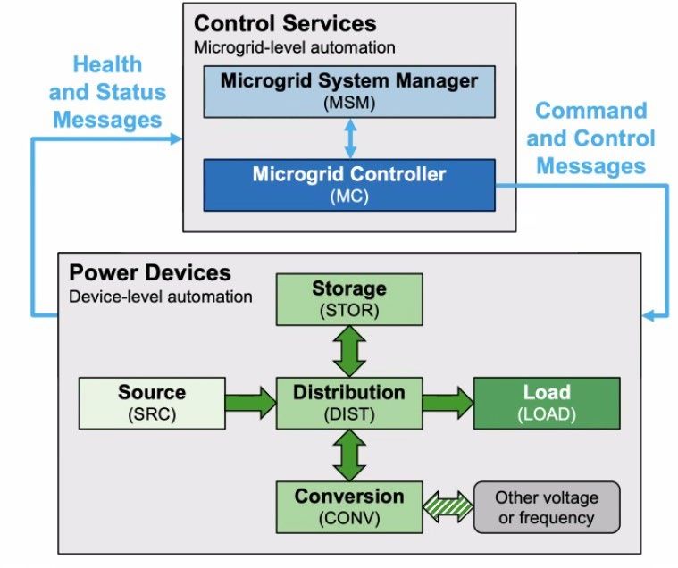
5.5. Power System Integration
Unlike diesel spot generators, a deployable wind turbine will not be directly connected to a load unless
the load is a rechargeable battery as in the case of the human-portable system. The deployable wind
turbine should be designed to integrate into hybrid power systems to include, at a minimum, a battery
storage device, but also likely diesel generators and solar photovoltaics. These could be incorporated as
part of an integrated power system (see Appendix G for examples) or as part of a distributed microgrid
with some sort of control system. Currently, the DoD has a draft Tactical Microgrid Standard (TMS)
(more details in Appendix E), but the TMS needs further development to account for the non-
dispatchable nature of wind energy production. A microgrid standard is also lacking on the industry side,
though both the IEC and UL (UL3001) are working on microgrid standards. Until a DoD standard is in
place, deployable turbines should be designed to meet IEEE 1547-2018 and (when they are released) the
IEC and UL microgrid standards. Another important design consideration for hybrid microgrid power
systems is the energy management strategy. The choice of using dispatchable diesel power vs. non-
dispatchable renewable power and also battery charge and discharge timing can all have significant
impacts on component life, efficiency, and overall fuel savings. This is an active area of research and
development broadly.

5.6. Institutional Considerations
Beyond the technical considerations discussed in the prior sections, a further important consideration in
the successful deployment of wind technology to support military operations is the institutional
characteristics of the Department of Defense or other end use customers, governments, and agencies.
Moving from short-lived, one-off technology solutions to a longer-term Program of Record requires
ongoing engagement with various personnel from soldiers in the field to senior military leadership. The
more successful designs will be simple to understand, operate with minimal or no training, and provide a
tangible benefit to the mission.

 21
APPENDIX A. CONTAINER ANALYSIS
An analysis was performed of the maximum size turbine that can be transported in standard 20-ft and
40-ft ISO shipping containers. Table 3 lists container dimensions.

 Table 3. Standard shipping container dimensions [9]

 Tare
 Exterior Interior Door Opening
 Weight
 Length Width Height Length Width Height Width Height
20-ft 20 ft 8 ft 8 ft 6 in. 19 ft 3 in. 7 ft 8 in. 7 ft 9 7/8 in. 7 ft 8 in. 7 ft 5 in. 5,050 lbs.
Standard
Container (6.1 m) (2.4 m) (2.6 m) (5.9 m) (2.3 m) (2.4 m) (2.3 m) (2.3 m) (2,290 kg)
40-ft 40 ft 8 ft 8 ft 6 in. 39 ft 5 in. 7 ft 8 in. 7 ft 9 7/8 in. 7 ft 8 in. 7 ft. 5 in. 8,000 lbs.
Standard
Container (12.2 m) (2.4 m) (2.6 m) (12.0 m) (2.3 m) (2.4 m) (2.3 m) (2.3 m) (3,629 kg)

Assumptions
Turbine system components to be transported in the container include blades, tower, nacelle,
foundation base (analyzed in Appendix B), inverter, and controls. Although larger turbines may require
multiple containers for transport, it is preferred to have a complete turbine system in a single container.
The assumed turbine archetype for this analysis is a horizontal axis wind turbine.

Blades
A horizontal axis wind turbine will typically have three
blades. Blade length is important as energy capture is
proportional to the square of the rotor radius. For this
analysis, the maximum blade length is assumed equal
to the interior length of the container. There are three
ways to gain extra blade length: blades can be
segmented, blades can be placed corner-to-corner in
the container, or rotor diameter can be increased using
hub extenders. Segmented blades and hypotenuse
placement are assumed to be impractical at this time,
but the use of hub extenders will be further examined.

Hub extenders, shown in Figure 4, are occasionally
used in the industry to increase rotor diameter, and Figure 4. Northern Power Systems NPS 100C-24 with
thus energy capture, without increasing blade length. hub extenders (en.wind-turbine-models.com)
Based on past and current hub extender use, this
analysis assumes a maximum increase in rotor diameter
of 14%, which will increase rotor swept area by 31%.

 22
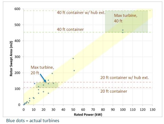
Maximum Rotor Size
Table 4 shows the maximum rotor radius, rotor diameter, and rotor swept area for the 20-ft and 40-ft
container for both the baseline assumption of no hub extenders (blade length is equal to rotor radius)
and with hub extenders (assuming a maximum increase in rotor radius of 14%).

 Table 4. Maximum rotor size per container
 Container Max rotor radius Max rotor diameter Max rotor swept area
 2 2
 20 ft (no hub extenders) 5.87 m (19.3 ft) 11.7 m (38.5 ft) 108 m (1,164.2 ft )
 2 2
 20 ft with hub extenders 6.69 m (22 ft) 13.4 m (43.9 ft) 141 m (1512 (1,512.9 ft )
 2 2
 40 ft baseline 12.0 m (39.4 ft) 24.0 m (78.8 ft) 454 m (4,881 ft )
 2 2
 40 ft (no hub extenders) 13.7 m (44.9 ft) 27.4 m (89.9 ft) 589 m (6,343.4 ft )

Maximum Turbine Power
Figure 5 shows the rotor swept areas and rated power of a variety of small wind turbines currently on
the market. The yellow shaded region represents the range of rated power for a given swept area. The
general industrywide trend is toward low specific power (rated power measured in watts per square
meters of swept area); rotor size is increasing for a given rated power, thus increasing energy capture in
lower wind speed regimes. For the 20-ft container, the rated power of the maximum rotor size could
range from the 11-kW Gaia turbine with its 13-m (42.7-ft) rotor to the 30-kW Bestwind with a 13.1-m
(43-ft) rotor. For the 40-ft container, the rated power of the maximum rotor size could range from
about 80 kW to 125 kW, but with fewer models in this range, a maximum rated power of 100 kW is a
reasonable assumption.

 Figure 5. Rated power versus rotor swept area

 23
Tower Height
As shown in Figure 6, towers are typically either monopole (no guy wires), guyed towers, or perhaps
telescoping for deployable turbines. They can be a single piece or segmented. This analysis assumes the
maximum tower segment length is equal to the interior length of the container.

 Figure 6. Single-piece, monopole tower (left, Pika Energy turbine, NREL PIX 31470), segmented,
 guyed tower (center, Bergey Windpower turbine, NREL PIX 16742), and telescoping tower
 (Uprise Energy turbine, Idaho National Lab)
The maximum tower height for each container size is presented in Table 5. For the 20-ft container, the
maximum tower height ranges from 5.9 m (19.3 ft) for one segment to 29.3 m (96.3 ft) for five
segments. For the 40-ft container, the maximum tower height ranges from 12.0 m (39.4 ft) for one
segment to 36.0 m (118.3 ft) for three segments. Although more tower segments could fit into the
container, a maximum tower height of approximately 30 m (~100 ft) was assumed for a deployable
system. The tower will require a foundation, which is analyzed in Appendix B.

 Table 5. Maximum tower height options per container
 Max Tower Height 20-ft Container Max Tower Height 40-ft Container
 5.87 m (19.3 ft) 1 segment 12.0 m (39.4 ft) 1 segment
 11.7 m (38.5 ft) 2 segments 24.0 m (78.8 ft) 2 segments
 17.6 m (57.8 ft) 3 segments 36.0 m (118.3 ft) 3 segments
 23.5 m (77.0 ft) 4 segments
 29.3 m (96.3 ft) 5 segments

Nacelle
The nacelle includes the hub (connects blades to shaft), generator, braking system, pitching system, yaw
system, gearbox, and any up-tower power electronics. The hub is sometimes a separate component,
especially for larger turbines. The weight and size of the nacelle increases with turbine size and must be
accounted for in the container. For example, the nacelle for the 10-kW Bergey Excel 10 weighs 444.5 kg
(980 lbs.), whereas the nacelle for the 100-kW NPS 100-C weighs 6,291 kg (13,869 lbs.)

 24
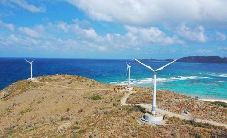
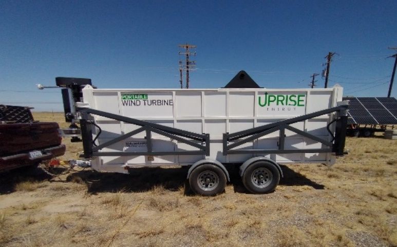
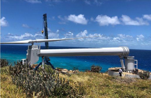
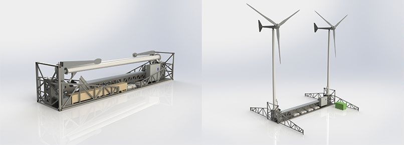
Inverter, Controls, Battery
The power electronics and battery energy storage systems are important components in the wind turbine
system. These components will typically be mounted in or on the container and thus must be accounted
for. For example, the new Intergrid IG25 inverter, used in turbines up to about 25-kW rated power,
weighs 39 kg (85 lbs.). Battery systems can add significant weight to the system; for example, the 15-
kWh RELiON lithium iron phosphate weighs 176 kg (388 lbs.).

Examples of Containerized Systems
Figure 7 shows the wind + solar + storage “hybrid cube” system from HCI Energy that transports in a
20-ft shipping container. The wind turbine is the Skystream 3.7 with 2.4-kW rated power, 3.72-m (12.2-
ft) rotor diameter, and 10.9-m2 (117-ft2) rotor swept area. The total system weight is 18,000–22,000 lbs.
(8,166–9,979 kg), depending on the options selected. The two-segment, 40’-ft tower transports on the
container top and is tilted up onsite using a gin pole.

Figure 6 shows the telescoping tower from Uprise Energy. Figure 8 shows the system transformed into
a portable trailer that fits within a standard 20-ft container for transport. The trailer, which serves as the
turbine foundation, contains the 10-kW turbine with its five 3.4-m (11.1-ft) blades, providing 37.4-m2
(403-ft2) rotor swept area, the 14.5-m (47.6-ft) telescoping tower, inverter, and batteries. The total
system weighs 5,443 kg (12,000 lbs.).

 Figure 7. HCI Energy Figure 8. Uprise Energy system in trailer mode
 hybrid cube (photo from Idaho National Lab)

Figure 9 shows the Deployable Advanced Renewable Power System (DARPS) under development by
Bergey Windpower. This system transports as a 40-ft container (not inside a container) and is made
stackable with other 40-ft containers. Bergey utilizes two of their Excel 15 turbines on 11.6-m (38-ft)
tilting monopole towers along with batteries and microgrid power electronics. The total system weight is
8,849 kg (19,509 lbs.).

Figure 10 shows the 100-kW turbine from Northern Power Systems being deployed on Necker Island.
The complete system, including the turbine, 24-m (79-ft) diameter rotor, 20-m (66-ft) tilting monopole

 25
You can also read