Zero-Power communication - Oppo

Page created by Kyle Nunez
 
CONTINUE READING
Zero-Power communication - Oppo
Zero-Power
communication
Zero-Power communication - Oppo
CONTENT   01.                                           01
          Introduction

          02.                                           05
          Typical use cases of
          Zero-power Communication

          03.                                           21
          Technical principles of
          Zero-power Communication

          04.                                           31
          Overall Design of
          Zero-power communication system

          05.                                           43
          Key techniques and the challenges of
          Zero-power communication

          06.                                           62
          Integration of Zero-Power communication and
          other key techniques of 6G

          07.                                           77
          Epilogue
Zero-Power communication - Oppo
01       Zero-Power communication                                                                                                                    Introduction      02

                                                                 Recent progress of

INTRODUCTION                                               1.1   Internet of Things
In recent years, 3GPP have standardized series of                Digital mobile communication has experienced 2G, 3G,4G and it is still continuing to evolve. Current-
technologies on IoT (Internet of Things), which achieves         ly the 5th generation mobile network can well meet people's needs in voice communication, digital
the design targets of low cost, low power consumption,           mobile communication and mobile broadband Internet communication. In the meantime, the
massive connection and deep coverage. These IoT                  demand for the internet of things has also been gradually risen with the development of society and
technologies can well meet the requirements of diverse           economy. Technologies and standards related to the Internet of things (IoT) have been developed
scenarios. However, there are still many other scenari-          and evolved since 2010. Among them, 3GPP (3rd Generation Partnership Project) standardizes series
os that require the terminal to have ultra-low power             of IoT technologies such as MTC (Machine Type Communications), NB-IoT (Narrow Band IoT) and
consumption or even zero power consumption,                      RedCap (Reduced Capability UE). Techniques used in MTC and NB IOT, such as reduced bandwidth,
ultra-low cost, very small size etc. With techniques             single antenna, reduced peak rate, half duplex and reduced transmission power have significantly
such as RF power harvesting, backscattering and low              lowered the cost of IoT terminals. Furthermore, power consumption of IoT terminals is greatly
power computing, zero power communication can well               decreased by the introduction of eDRX (enhanced Discontinuous Reception) and PSM (Power Saving
meet these new requirements. Due to its excellent                Mode). At the same time, existing IoT solutions can also support a large number of terminals for
characteristics, zero-power communication is expected            simultaneous network accessing to meet the need of massive connection.
to become one important candidate of next generation
technology on Internet of Things.

                                                                 Unsatisfied communication
                                                           1.2   requirements of IoT
                                                                 Existing technologies such as MTC and NB-IoT have achieved low cost, low power consumption and
                                                                 massive connection of Internet of Things terminals, they meet the communication requirements of
                                                                 Internet of Things in many scenarios. However, there are still many situations where communication
                                                                 requirements cannot be satisfied with existing technologies, such as:

01
                                                                 Harsh communication environment

                                                                 Some scenarios of the Internet of things may face extreme environments such as high temperature,
                                                                 extremely low temperature, high humidity, high pressure, high radiation or high-speed movement.
                                                                 For example, there are hazardous circumstances in an ultra-high voltage power station, railway for
                                                                 high-speed moving trains, environmental monitoring in high-cold areas, industrial production lines
                                                                 and so on. In these scenarios, due to restrictions of the working environment of conventional power
                                                                 supplies, the existing Internet of things terminals will not work. In addition, maintenance of IoT devic-
                                                                 es (e.g., replacing batteries) becomes challenging under extreme conditions.

                                                                 Requirements of ultra-small form factor of the IoT terminal

                                                                 For some Internet of things communication scenarios, e.g., food traceability, commodity circulation
                                                                 and smart wearables, it requires the terminal to have an ultra- small size to facilitate application in
                                                                 these scenarios. For example, the IOT terminal used for commodity management in the circulation
                                                                 usually uses the form of electronic label and is embedded into the commodity packaging in a very
                                                                 small form factor. As another example, light-weight wearable devices can improve the user experi-
                                                                 ence while meeting communication needs.
Zero-Power communication - Oppo
03    Zero-Power communication                                                                                                                                                                   Introduction     04

             Requirements of ultra-low cost IoT communication                                                        As shown in Figure 1.3-1, compared with existing technologies such as MTC, NB-IoT and RedCap,
                                                                                                                     zero-power communication will have significant advantages in terms of terminal power con-
             Many communication scenarios of the Internet of things require that the cost of the terminal of the     sumption, terminal size and terminal cost. For example, in terms of power consumption, the ter-
             Internet of things to be low enough to enhance its competitiveness compared with other alternative      minal power consumption is expected to be reduced from tens of milliwatts of NB-IoT terminals
             technologies. For examples in logistics or warehousing scenarios, in order to facilitate the manage-    to dozens of microwatts or even several microwatts. In terms of cost, the terminal cost is
             ment of a large number of goods in circulation, the terminal can be attached to each item in order to   expected to be reduced from more than ten RMB yuan of the cheapest NB-IoT terminal in the
             complete the accurate management of the whole logistics process through the communication               above technologies to 1 RMB yuan or even lower. Therefore, with the obvious differences
             between the terminal and the logistics communication network.                                           between the above and other technologies, zero-power communication is expected to become
                                                                                                                     an important candidate technology for the next generation of Internet of things.

             Therefore, for the Internet of things communication scenarios represented by the above ,it requires
             the terminals to fulfill the requirements of battery-free, ultra-low power consumption, very small
             size and ultra-low cost. The existing IoT technology cannot meet these requirements. How to solve
             these unsatisfied communication requirements of the Internet of things and better serve the eco-
             nomic and social development is a problem worthy of discussion and study.                                            MTC / NB-IoT                    RedCap                   ZP loT

                                                                                                                           2010                       2015                      2020                     2025

             Development vision of
1.3
                                                                                                                                     Figure 1.3-2 Development roadmap of Internet of things technology

             zero-power communication
             Zero-power communication technology utilizes key techniques such as RF energy harvesting, back-         To sum up, zero-power communication will be committed to meet the communication require-
             scattering communication and low-power computing. Zero-power communication obtains energy by            ments that the existing technologies are still unable to meet and achieve a good complementar-
             harvesting radio waves in the space to drive the terminal. Therefore, the terminal can be bat-          ity with the existing technologies, so as to meet the multi-level and multi-dimensional communi-
             tery-less without using conventional batteries, so it can effectively reduce the size and cost of the   cation requirements of the Internet of things.
             terminal. Furthermore, backscattering communication and low-power computing technologies make
             the terminal achieve an extremely simplified RF and baseband circuit structure, which can greatly
             reduce the terminal cost, terminal size and circuit energy consumption. Therefore, zero-power com-
             munication is expected to achieve battery-less terminals to meet the communication needs of the
             Internet of things with ultra-low power consumption, very small size and ultra-low cost.

             Due to its good characteristic of battery-less, such kind of terminal is named zero-power terminal
             and the corresponding communication procedure is called zero-power communication.

                  6
                  5
                  4
                  3
                  2
                  1
                  0
                      Power         Cost         Latency      Connections   Throughput        Size

                       NB-IoT              MTC             RedCap            ZP IoT

                                     Figure 1.3-1 Comparison of IoT technologies
Zero-Power communication - Oppo
05        Zero-Power communication                                                                                     Typical use cases of Zero-power Communication       06

                                                                    Industrial Wireless
TYPICAL USE CASES                                             2.1   Sensor Network

OF ZERO-POWER                                                       IWSN has a wide range of applications, including building automation, industrial process automa-
                                                                    tion, power facility automation, automatic meter reading and inventory management, environmen-

COMMUNICATION                                                       tal sensing, security, production line monitoring, etc. A large number of sensor nodes are often
                                                                    deployed in these application scenarios, and the sensor nodes are used for temperature and humidi-
The outstanding technical advantage of zero-power com-              ty monitoring, vibration monitoring, production line monitoring, industrial automation and numerical
munication is battery free. Due to the use of keytechnolo-          management, hazardous event monitoring, etc. Compact and low-cost sensor equipment is the key
gies such as energy harvesting, backscattering communi-             to realize large-scale deployment of IWSN. In order to meet technical challenges and meet the
cation, and low-power computing, the terminal can be                needs of various IWSN applications, it is necessary to follow the design objectives of low-cost and
battery-free and support extremely low hardware complexi-           small sensor nodes.
ty. Therefore, zero-power communication can meet the
requirements of ultra-low power consumption, extremely              In view of the ultra-low power consumption, extremely small size, and extremely low cost of the
small size, and extremely low cost.                                 zero-power communication terminals, zero-power communication will have a wide range of poten-
                                                                    tial application in the IWSN scenario. In particular, it should be pointed out that the characteristics of
It can be predicted that zero-power technology will have            battery-free with zero-power communication terminals can also extend zero-power communication
significant advantages in a wide range of applications.              to application scenarios that cannot be covered by legacy Internet of Things communication tech-
For example, industrial wireless sensor network (IWSN)              nologies. For example, in some IWSN applications, industrial sensor nodes may be deployed in harsh
for vertical industries, smart transportation, smart logis-         environments and special location spaces, or even in extremely hazardous environments (such as
tics, smart warehousing, smart agriculture, smart cities,           high/low temperature, high-speed moving or rotation parts, high vibration conditions, humidity, etc.).
and energy field, as well as applications for individual             In these application scenarios, on the one hand, due to the working environment, terminals driven
consumers such as smart wearables, smart home and                   by conventional battery may not work properly (restricted by the requirements of the physical and
medical care, etc. In this section, we will select some of          chemical characteristics of the battery ). On the other hand, when using traditional terminals, the
the scenarios to illustrate the potential application of            high network maintenance costs and even the limitations of the working environment would make
zero-power communication.                                           network maintenance impossible to perform. Therefore, the existing terminals cannot meet the
                                                                    requirements in such application scenarios.

                                                                    Applying zero-power communication technology in IWSN with energy harvesting and backscattering

02
                                                                    technologies, sensor nodes can achieve battery-free and ultra-low power consumption, which will
                                                                    greatly solve the limited battery life cycle problem of sensor nodes and greatly extend their service
                                                                    life. At the same time, the battery-free feature of zero-power communication will also greatly
                                                                    reduce the maintenance cost of sensor nodes and even achieve maintenance-free.

                                                                    Therefore, the combination of zero-power communication and IWSN can greatly expand the applica-
                                                                    tion scenarios of IWSN, increase the service time of sensor nodes, and reduce deployment and
                                                                    maintenance costs.
Zero-Power communication - Oppo
07   Zero-Power communication                                                                                                                                                              Typical use cases of Zero-power Communication          08

               Some typical use cases for IWSN scenario are as follows:                                                    Typical requirements for IWSN scenario are as follows:

                                                                                                                          Terminal requirements:           The zero-power terminal is in the form of an electronic tag, which can be integrated
            Tire management                                                                                                                                with memory for data access or integrated with sensors for information collection.
                                                                                                                                                           Since it is generally a large-scale application (each device will have a tag), the
            The zero-power terminal (equipped with corresponding sensors) is embedded in the tire, and the                                                 cost and power consumption of the tag need to be taken into account.
            basic information of the tire (such as tire pressure, tire life, brand, factory, etc.) is collected and
            recorded by the terminal [1], so as to facilitate the manufacturing, after-sales and use management                                            Tag size:extremely small size, convenient for large-scale application.
            of the tire. The significant advantage of using a zero-power terminal is that data can be collected                                             Tag type: paper tag and anti-metal tag.
            and recorded without damaging or removing the tire.                                                                                            Tag power consumption:the terminal power consumption is less than 1mw,
                                                                                                                                                           battery free and maintenance free.
                                                                                                                                                           Working environment:It can match and work normally in special environ-
            Railway Track monitoring                                                                                                                       ments such as high temperature, high pressure, extreme cold, radiation, etc.
                                                                                                                                                           Communication distance:support communication in the range of tens of
            The zero-power terminal equipped with corresponding sensors is deployed under railway       [2]
                                                                                                              , and the                                    meters to hundreds of meters.
            sensors provide pressure, heat and other information of the track during and after a train run on the
            track.

            Environmental Information Collection

            Information is collected in some special environments (such as high temperature, high pressure,
            extreme cold, radiation, etc.). Such as ultra-high voltage stations, substations and other application
            environments.                                                                                                 Network requirements:            Flexible deployment based on cellular network:Network equipment can be
                                                                                                                                                           deployed in outdoor pole stations, indoor with DIS (Digital Indoor System) sta-
                                                                                                                                                           tion spacing deployment, to provide basic coverage.
                                                                                                                                                           Coverage requirements: coverage distance requirements of a single station
                                                                                                                                                           (indoor >30m, outdoor >100m).
                                                                                                                                                           Network security:authorization-based tag reading to protect user privacy
                                                                                                                                                           and data security.
                                                                                                                                                           Connection requirements:Support sufficient system capacity and support
                                                                                                                                                           data reading from a large number of terminals.

                                   Figure 2.1-1 Application of Zero-power Technology in IWSN
Zero-Power communication - Oppo
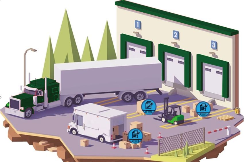
09   Zero-Power communication                                                                                                                                                   Typical use cases of Zero-power Communication               10

            Logistics and                                                                                                Specifically, zero-power technology can realize smart warehouse management and improve

2.2         Warehousing
                                                                                                                         warehouse efficiency and productivity through the following:

                                                                                                                      Support Batch reading
            With the sustained and stable development of China's and world’ s economy, the economic volume
                                                                                                                      A larger number of zero-power tags are read at the same time. When the goods arrive at the ware-
            is getting larger and larger, followed by the further expansion of logistics scale. Logistics is a very
                                                                                                                      house, the wireless tags attached to the goods can be read in batches (for example, read thousands
            important link in the supply chain of commodity circulation and occupies an important position in the
                                                                                                                      of tags per second) to accurately obtain goods information, such as size/weight, manufacturer, expi-
            national economy, while warehousing is the core link of modern logistics.
                                                                                                                      ration date, serial number, production line, etc., which can help to improve the efficiency and accu-
                                                                                                                      racy of logistics storage.
            In logistics and warehousing application scenarios, a large number of packaging / goods need to be
            transferred, stored, loaded, unloaded and inventoried frequently at logistics stations or warehouses
                                                                                                                      Support Large coverage
            (tens of thousands of square meters). With the occurrence of warehouse ordering, goods warehous-
            ing, goods management and goods outbound, there will be a lot of storage information, which gen-          With zero-power communication, a wider range of reading and writing can be supported                      [3]
                                                                                                                                                                                                                                      . In the
            erally has the characteristics of frequent data operation and large amount of data.                       warehouse, one or a few network equipment are deployed to cover the whole warehouse. The wire-
                                                                                                                      less tag attached to the goods or containers will save its basic information and location information.
            In order to carry out digital information management of logistics packages/goods and improve the          Through the center network nodes set up in the warehouse, it can identify all the goods in the warehouse
            management efficiency of logistics and warehousing, a terminal can be attached on the surface of           timely and quickly and help to take inventory quickly. It is convenient for managers to understand the distri-
            the packages/goods for acquisition of logistics information and management of the entire logistics        bution and total amount of inventory in time and realize the rapid prediction of storage demand.
            process. Therefore, small terminal size is more conducive to industry applications. At the same time,
            due to the huge number of goods and when economic cost is taken into considerations, express              Support Mobility management
            delivery or warehouse suppliers can only accept extremely low-cost terminals.
                                                                                                                      Tags can be used to track location information      [4]
                                                                                                                                                                                . When the goods move in the warehouse, the net-
            Zero-power terminal has the characteristics of extremely low cost, small size, maintenance-free,          work equipment can identify and update the tag information in time. When it is necessary to pick
            durable, and long life cycle. In logistics and warehousing, the use of zero-power terminal to record,     and choose the corresponding goods, the tag can be read in the whole warehouse and it can quickly
            save, and update goods information, and build a logistics and warehousing system based on the             locate the goods and greatly improve the picking efficiency of the goods.
            zero-power communication can further reduce operating costs and significantly improve the effi-
            ciency of logistics and warehousing management. It also contributes to the realization of smart
            logistics and smart warehousing.

                                Figure 2.2-1 Zero-power tags in smart logistics and smart warehousing                                 Figure 2.2-2 Application of Zero-power technology in Smart Warehousing
Zero-Power communication - Oppo
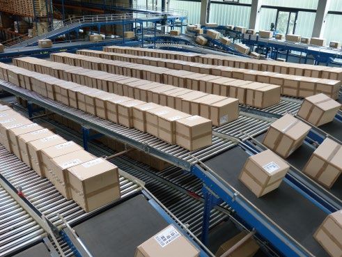
11         Zero-Power communication                                                                                                                                           Typical use cases of Zero-power Communication   12

     Typical requirements for smart logistics and smart warehousing scenario are as follows:
                                                                                                                              Smart
 Terminal requirements:               The zero-power terminal is in the form of a simple electronic tag. Since it is
                                                                                                                        2.3   Home
                                      generally a large-scale application (each good will have a tag), the cost, size
                                                                                                                              Smart home takes housing as the platform and connects various devices at home through the Inter-
                                      and power consumption of the tag need to be taken into account.
                                                                                                                              net of things to build an efficient and livable system. Smart home makes use of various functions
                                                                                                                              and means such as automatic control, lighting control, temperature control, anti-theft and alarm
                                      Tag size:extremely small size, convenient for large-scale application.
                                                                                                                              control of home appliances to make the home environment safer, more convenient and more com-
                                      Tag cost: due to the huge number of goods in logistics and storage,
                                                                                                                              fortable. Sensors and small devices in smart homes scenario can communicate using backscattering
                                      extremely low cost is required.
                                                                                                                              technology [5].
                                      Tag power consumption:the terminal power consumption is less than 1mw,
                                      battery free and maintenance free.
                                                                                                                              Zero-power communication can achieve battery-free, which can greatly increase the service time of
                                      Communication distance:support communication in the range of tens of
                                                                                                                              corresponding devices at smart homes and reduce maintenance costs. At the same time, due to its
                                      meters to hundreds of meters.
                                                                                                                              ultra-low cost, extremely small size, washable, flexible/foldable shape factors, it can be deployed
                                                                                                                              flexibly at smart homes, such as embedded in walls, ceilings and furniture, or attached to keys,
                                                                                                                              passports, clothes and shoes. Zero-power communication can expand the application of smart
                                                                                                                              home scenarios and is extremely attractive to the smart home field.

 Network requirements:                Flexible deployment based on cellular network:Network equipment can be
                                      deployed in outdoor pole stations, indoor with DIS station spacing deployment,
                                      to provide basic coverage.
                                      Coverage requirements: coverage distance requirements of a single station                        PASS

                                      (indoor >30m, outdoor >100m).
                                      Network security:authorization-based tag reading to protect privacy and
                                      data security.
                                      Reading efficiency: large quantities of goods require simultaneous detection
                                      of a large number of tags (e.g., thousands per second).

                                                                                                                                                Figure 2.3-1 Application of Zero-power technology in Smart Home

                                                                                                                                 Typical use cases for Smart Home scenario are as follows:

                                                                                                                              Item search

                                                                                                                              An extremely small, washable, flexible, foldable zero-power terminal can be attached to some items
                                                                                                                              which are easily lost in the house, such as keys, passports, bank cards, wallets and others. When
                                                                                                                              you need to find these items, you can quickly locate and find the lost items with the help of
                                                                                                                              zero-power communication.
Zero-Power communication - Oppo
13          Zero-Power communication                                                                                                                                                                Typical use cases of Zero-power Communication                    14

                   Environmental monitoring and alarm
                                                                                                                                Smart
                   Zero-power terminals are integrated with sensors to monitor the temperature, humidity, etc. of the
                   house, and can also be used for warning in case of emergency such as gas leakage. The battery
                                                                                                                          2.4   Wearable
                   free feature of zero-power terminal can greatly increase the service time of the equipment and real-
                                                                                                                                It is user-centered in the smart wearable scenario and various devices worn by consumers are con-
                   ize maintenance free.
                                                                                                                                nected through the Internet of things technology, which has been applied in many fields (such as
                   Intelligent control                                                                                          health monitoring       [7]
                                                                                                                                                              , activity recognition   [8][9]
                                                                                                                                                                                                , assisted living   [10]
                                                                                                                                                                                                                           , mobile perception   [11]
                                                                                                                                                                                                                                                        , smart clothing
                                                                                                                                [12]
                                                                                                                                       , indoor positioning    [13]
                                                                                                                                                                      , etc.). At present, the mainstream product forms include form factors relat-
                   Zero-power terminals are integrated with sensors, which can realize intelligent control of home
                                                                                                                                ed to watches (including watches and wristbands), form factors related to shoes (including shoes,
                   devices. For example, it can be used to control the switch of washing machines, air conditioners,
                                                                                                                                socks or other products to be worn on legs), form factors related to Glass (including glasses, hel-
                   televisions, curtains, etc. Home robots can also be navigated and provided more sophisticated con-
                                                                                                                                mets, headband, etc.). In addition, it also includes various non-mainstream product forms such as
                   trol by tags embedded/attached to doors and furniture [6].
                                                                                                                                smart clothes, schoolbags, crutches and accessories.

                                                                                                                                Smart wearable devices driven by batteries have a relatively short battery life. If more functions are
                                                                                                                                enabled, the power consumption will further increase, and users often need to charge frequently to
     Typical requirements for Smart Home scenario are as follows:                                                               ensure the normal use of the device. This will greatly affect the user experience.

                                                                                                                                Zero-power terminal has excellent characteristics such as extremely low cost, extremely small size,
 Terminal requirements:                The zero-power terminal is in the form of an electronic tag, which can be inte-
                                                                                                                                extremely low power consumption (battery-free), flexible/foldable, and even washable. It is particu-
                                       grated with memory for data access or sensors for sensor information collec-
                                                                                                                                larly suitable for smart wearable scenarios and easy to be accepted by consumer-related industries
                                       tion. In home applications, its cost, power consumption, size, waterproofing
                                                                                                                                (such as kindergartens, garment factories, etc.). On the one hand, zero-power terminals can obtain
                                       and foldability all need to be considered.
                                                                                                                                energy through energy harvesting, which will fundamentally solve the problem that smart wearable
                                                                                                                                devices need to be charged frequently. On the other hand, the zero-power terminal has the advan-
                                       Tag size:extremely small size, convenient for large-scale application.
                                                                                                                                tages of low cost, small size, soft material, washable and foldable, which greatly improves the com-
                                       Tag type:Paper tag and anti-metal tag, support cleaning, with flexible and
                                                                                                                                fort of wearing and makes the user experience better.
                                       foldable shape.
                                       Tag power consumption:Battery free, not involve battery replacement and
                                       other related maintenance issues.
                                       Communication distance:Support communication in the range of tens of
                                       meters to hundreds of meters (Indoor).
                                       Number of connections:Support tens to hundreds of device connections.
                                       Communication delay: Adjustment of intelligent household appliances: 10ms
                                       to 100ms. Home positioning: 100 milliseconds to second level.

 Network requirements:                   Flexible deployment:Use smart terminals (smart phone or CPE) as gateway
                                         devices, or directly connect to base stations.
                                         Coverage requirements: coverage distance requirements of a single station
                                         (Indoor 10-30m (connected to smart devices). Outdoor >100m (directly con-
                                         nected to base station).
                                         Network security:authorization-based tag reading to protect privacy and
                                         data security.
                                         Large connection:There are a large number of indoor zero-power terminals,
                                         ranging from tens to hundreds.
                                         Energy harvesting signal: The signal of smart devices (e.g., smart phones,
                                         CPE and WIFI) in the home can be used as wireless power sourcing signal for
                                         the zero-power terminal.
                                                                                                                                                       Figure 2.4-1 Application of Zero-power technology in Wearable field
Zero-Power communication - Oppo
15          Zero-Power communication                                                                                                                                                           Typical use cases of Zero-power Communication   16

                      Typical use cases for smart wearable are as follows:
                                                                                                                                            Medical
                   Health monitoring                                                                                                  2.5   Health
                   Zero-power terminal is integrated with sensors, embedded in wristbands           [14]
                                                                                                           , shoes, socks and other
                   wearable products for health monitoring and timely feedback on people's physical condition. Sleep                        The medical health field involves patient information management, health data monitoring and
                   status, weight information, heart rate, blood pressure and other data are monitored and collected                        management, medical emergency management, drug storage, blood information management,
                   via the terminal.                                                                                                        drug preparation error prevention, medical devices and drug traceability, information sharing and
                                                                                                                                            interconnection, etc. In the process of medical treatment, it is necessary to ensure that the patient
                   Positioning and tracking                                                                                                 uses the correct medicine, the correct dosage, and the correct medication method at the correct
                                                                                                                                            time. At the same time, the clinical medical process requires high-quality monitoring and manage-
                   Zero-power terminal can support positioning      [15]
                                                                           , and it can be used for positioning and tracking of
                                                                                                                                            ment throughout the entire process.
                   the elderly, children or hospital patients when they get lost. More comfortable materials can opti-
                   mize the wearing experience, and the zero-power feature can greatly increase the service time.                           Zero-power terminal has excellent characteristics such as extremely low cost, extremely small size,
                                                                                                                                            extremely low power consumption (battery-free), flexible foldable, washable, etc. It can help hospi-
                   Portable payment                                                                                                         tals to realize intelligent medical treatment and intelligent management of things, and support the
                                                                                                                                            digital collection, processing, storage, transmission and sharing of medical information, equipment
                   Bound with personal information, zero-power terminal can be used for portable payment such as
                                                                                                                                            information, drug information, personnel information and management information within the hospi-
                   bus, subway, shopping etc.
                                                                                                                                            tal. In addition, the excellent characteristics of zero-power technology make it possible to perform
                                                                                                                                            in-body communication and treatment. There are already some related researches on in-body com-
                                                                                                                                            munication based on backscattering in the industry [16][17].
     Typical requirements for Smart Home scenario are as follows:

 Terminal requirements:                The zero-power terminal is in the form of an electronic tag, which can be inte-
                                       grated with memory for data access or integrated with sensors for sensor
                                       information collection. For the sake of wearing convenience, it should have a
                                       small size, battery free, waterproof, flexible and foldable shape.

                                       Tag size:Extremely small size, convenient to wear.
                                       Tag type: Paper tag and anti-metal tag, support cleaning, with flexible and
                                       foldable shape.
                                       Tag power consumption:Battery free, not involve battery replacement and
                                       other related maintenance issues.
                                       Communication distance:Support communications within a range of tens of
                                       meters (e.g., 30~50m). When a smart terminal is used as a relay, the commu-
                                       nication distance can be 1m to 2m.                                                                                     Figure 2.5-1 Application of Zero-power technology in Medical Health
                                       Number of connections:Support tens to hundreds of device connections.
                                       Service continuity requirements: Meet the periodic transmission require-
                                       ments, and the period of service traffic ranges from seconds to minutes.

 Network requirements:                 Flexible deployment:For wearable scenarios, since users carry both
                                       wearable devices and traditional smart terminals in most scenarios, smart ter-
                                       minals can serve as relay devices or gateway devices to collect and transmit
                                       data collected by wearable devices. Or wearable devices can directly connect
                                       to base stations.
                                       Network security:authorization-based tag reading to protect privacy and
                                       data security.
                                       Energy harvesting signal:The signal of smart terminal can be used as wireless
                                       power sourcing signal for the zero-power terminal.
17   Zero-Power communication                                                                                                                                                           Typical use cases of Zero-power Communication       18

               Typical use cases for Medical Health are as follows:                                                       Typical requirements for Medical Health are as follows:

            Special instrument monitoring
                                                                                                                          Terminal requirements:           The zero-power terminal is in the form of an electronic tag, which can also be
            Zero-power terminal has the characteristics of extremely small size and extremely low power con-
                                                                                                                                                           integrated with sensors.
            sumption (battery-free), which can assist the monitoring of special devices. For example, some
            devices implanted in the human body can use the zero-power terminal to monitor important param-                                                Tag size: Extremely small size.
            eters, ensure the normal operation of the relevant equipment and replace the faulty equipment                                                  Tag type: Paper tag and anti-metal tag, support cleaning, with flexible and
            timely. Because it is to monitor the equipment in the human body, the zero-power terminal without                                              foldable shape.
            battery can be maintenance-free, with a very long service life.                                                                                Tag power consumption:Battery free, not involve battery replacement and
                                                                                                                                                           other related maintenance issues.
            Subcutaneous / in-body health data collection                                                                                                  Communication distance:Support communication in the range of tens of
                                                                                                                                                           meters to hundreds of meters.
            Zero-power terminal integrated with sensors can be used for health data collection. For example,
                                                                                                                                                           Number of connections:Support tens to hundreds of device connections.
            Google Contact Lens   [18]
                                         collects radio frequency energy through wireless controller, and backscat-
                                                                                                                                                           Communication delay: 100 milliseconds to second.
            ters the measured blood sugar level to the wireless controller for diagnosis, so as to avoid the pain
            of blood test for diabetic patients. Due to its good features such as battery-free, waterproof and
            extremely small size, zero-power terminal can even be implanted into the human body for in-body
            health data collection. For example, capsule endoscopy      [19]
                                                                               can be used to record internal images of
            the gastrointestinal tract through the combination of a zero-power terminal and a sensor for medi-
            cal diagnosis, it is also able to take biopsies and release medication at specific locations of the entire     Network requirements:             Flexible deployment:Network equipment can be deployed in outdoor pole sta-

            gastrointestinal tract. While realizing more detailed examination, it can also avoid the pain of                                                tions, indoor with DIS (Digital Indoor System) station spacing deployment, to

            patients undergoing gastroscopy.                                                                                                                provide basic coverage.
                                                                                                                                                            Coverage requirements: coverage distance requirements of a single station
            Patient data collection and verification                                                                                                         (indoor >30m, outdoor >100m).
                                                                                                                                                            Network security:authorization-based tag reading to protect privacy and
            A very small zero-power terminal can be embedded in a wristband or clothing for data collection                                                 data security.
            and verification. In the process of patient diagnosis, taking medicine and treatment, data can be col-
            lected without disturbing patients, so as to realize efficient medical treatment management. It can
            also help to ensure that patients take the appropriate dose of drugs at the appropriate time, verify
            whether the name and specifications of infusion and injection drugs are correct, whether treatment
            items is completed, and whether there will be adverse reactions, etc.

            Management of drugs and medical devices

            The zero-power terminal is very small and can be attached to the bottle of equipment and medicine
            for the management and tracking of drugs and medical devices. Large medical centers generally
            have a large number of critical medical assets and storage bases for medical items, and logistics
            personnel have to find the required items from tens of thousands of items according to orders every
            day. The packaging of these medical items is highly similar while the use is totally different. There-
            fore, the hospital logistics department often has to spend huge manpower to find and check these
            items. In addition, the misplacement of medical items is likely to occur in the process of warehouse
            adjustment, resulting in large-scale damage or drug accidents after circulation to the market. By
            using the zero-power terminal, management can be facilitated, and the management efficiency, the
            reliability of medicines and medical devices can be improved.
19   Zero-Power communication                                                                                                                                               Typical use cases of Zero-power Communication   20

            References
2.6
            [1] Bharat P V, Sihna N, Pujitha K E. Tire pressure monitoring system using ambient backscatter tech-       [13] R. Harle, ‘‘A survey of indoor inertial positioning systems for pedestrians,’’ IEEE Commun. Sur-
            nology containing RF harvesting circuitry[J]. International journal of advance engineering and              veys Tuts., vol. 15, no. 3, pp. 1281–1293, 3rd Quart., 2013.
            research development, 2014, 1(6): 1-11.
                                                                                                                        [14] Yetisen A K, Martinez‐Hurtado J L, Ünal B, et al. Wearables in medicine[J]. Advanced Materials,
            [2] Papp A, Wiesmeyr C, Litzenberger M, et al. A real-time algorithm for train position monitoring          2018, 30(33): 1706910.
            using optical time-domain reflectometry[C]//2016 IEEE International Conference on Intelligent Rail
            Transportation (ICIRT). IEEE, 2016: 89-93.                                                                  [15] Wang K, Gu J F, Ren F, et al. A multitarget active backscattering 2-d positioning system with
                                                                                                                        superresolution time series post-processing technique[J]. IEEE Transactions on Microwave Theory
            [3] Akbar M B, Morys M M, Valenta C R, et al. Range improvement of backscatter radio systems at             and Techniques, 2017, 65(5): 1751-1766.
            5.8 GHz using tags with multiple antennas[C]//Proceedings of the 2012 IEEE International Sympo-
            sium on Antennas and Propagation. IEEE, 2012: 1-2.                                                          [16] Vasisht D, Zhang G, Abari O, et al. In-body backscatter communication and localization[C]//Pro-
                                                                                                                        ceedings of the 2018 Conference of the ACM Special Interest Group on Data Communication. 2018:
            [4] Liu W, Huang K, Zhou X, et al. Next generation backscatter communication: systems, techniques,          132-146.
            and applications[J]. EURASIP Journal on Wireless Communications and Networking, 2019, 2019(1):
            1-11.                                                                                                       [17] Voigt T, Rohner C, Yan W, et al. Towards secure backscatter-based in-body sensor networks
                                                                                                                        [C]//Proceedings of the 18th Conference on Embedded Networked Sensor Systems. 2020: 741-742.
            [5] Maselli G, Piva M, Stankovic J A. Adaptive communication for battery-free devices in smart
            homes[J]. IEEE Internet of Things Journal, 2019, 6(4): 6977-6988.                                           [18] https://en.wikipedia.org/wiki/Google_Contact_Lens

            [6] J. J. Pomárico-Franquiz, Y. S. Shmaliy, Accurate self-localization in RFID tag information grids        [19] https://en.wikipedia.org/wiki/Capsule_endoscopy

            using FIR filtering. IEEE Trans. Ind. Informat. 10(2), 1317–1326 (2014)

            [7] A. Pantelopoulos and N. G. Bourbakis, ‘‘A survey on wearable sensorbased systems for health
            monitoring and prognosis,’’ IEEE Trans. Syst., Man, Cybern. C, Appl. Rev., vol. 40, no. 1, pp. 1–12, Jan.
            2010.

            [8] E. Sazonov, Wearable Sensors: Fundamentals, Implementation and Applications. Amsterdam,
            The Netherlands: Elsevier, 2014.

            [9] O. D. Lara and M. A. Labrador, ‘‘A survey on human activity recognition using wearable sensors,’’
            IEEE Commun. Surveys Tuts., vol. 15, no. 3, pp. 1192–1209, 3rd Quart., 2013.

            [10] D. Dakopoulos and N. G. Bourbakis, ‘‘Wearable obstacle avoidance electronic travel aids for
            blind: A survey,’’ IEEE Trans. Syst., Man, Cybern. C, Appl. Rev., vol. 40, no. 1, pp. 25–35, Jan. 2010.

            [11] X. Zhang, Z. Yang, W. Sun, Y. Liu, S. Tang, K. Xing, and X. Mao, ‘‘Incentives for mobile crowd
            sensing: A survey,’’ IEEE Commun. Surveys Tuts., vol. 18, no. 1, pp. 54–67, 1st Quart., 2016.

            [12] K. Hartman, Make: Wearable Electronics: Design, Prototype, and Wear Your Own Interactive
            Garments. Sebastopol, CA, USA: Maker Media, 2014.
21       Zero-Power communication                                                                                           Technical principles of Zero-power Communication     22

TECHNICAL PRINCIPLES                                                                                                                        Energy harvesthing

OF ZERO-POWER
                                                                                                                                              Backscattering

                                                                                                                                     Low power-consumption comptuing

COMMUNICATION                                                                   Network Node                          Tag

Zero-power Communication mainly utilizes RF power harvest-                                               Figure 3-1 Zero-power communication system
ing, backscattering, and low-power computing technology to
implement battery-less terminal. As shown in Figure 3-1, the ter-          In zero-power communication system, the backscattering transmitter modulates and reflects the
minal obtains the energy to drive itself through energy harvest-           received RF signal to transmit data instead of generating the RF signal itself. This technology has

ing. It uses low-power computing and backscattering for data               been widely used in practical production, such as radio frequency identification (RFID), tracking
                                                                           equipment, remote switches, medical telemetry, and low-cost sensor networks.
transmission.

RF power harvesting aims to convert radio frequency energy
into direct current (RF-DC). The energy can be stored in an unit
such as a capacitor or it can be directly used to drive sensors,
logic circuits and digital chips. It enables the device to execute
operations such as computation, modulation of backscatter
                                                                           RF power
                                                                     3.1
signal, and collection and processing of sensor information.
                                                                           harvesting
                                                                           One of the most important functions of power harvesting is to collect electromagnetic waves and
                                                                           convert radio frequency energy into direct current (RF-DC). In zero-power communication, the col-
                                                                           lected energy is used to drive the load circuit (low-power computing, sensors, etc.) to achieve bat-

03
                                                                           tery-less communication.

                                                                           There are several challenges regarding RF power harvesting.

                                                                           1) It is difficult to collect RF energy in a wireless environment due to the low power density (e.g., less
                                                                           than 10nW/cm2). The RF power that can be effectively collected shall exceed a certain input power
                                                                           threshold, which can be called as RF power harvesting sensitivity of such device.

                                                                           2) In order to drive logic circuits or chips, DC voltage converted from RF energy shall meet the mini-
                                                                           mum output voltage requirements. It remains a big challenge to efficiently convert RF to DC under
                                                                           the condition of very low input power.

                                                                           3) Intelligently managing the collected or stored energy is also important for a good balance of com-
                                                                           munication and computing.
23   Zero-Power communication                                                                                                                                         Technical principles of Zero-power Communication   24

            Currently, it show by results from experimental researches that the RF energy conversion efficiency        The typical power harvesting circuits include half-wave rectifier (as shown in Figure 3.1-1), single
            is different for different input power and energy harvesting circuit designs. For example, the energy     shunt rectenna, single stage voltage multiplier (as shown in Figure 3.1-2), Cockcroft-walton/Grein-
            conversion efficiency at input power of -20dBm is often less than 10% while the conversion efficien-        acher charge pump, Dickson charge pump, modified Cockcroft-walton/greinacher charge pump).
            cy at input power of -1dBm is close to 50%. When input power is less than -30 dBm it is very chal-
            lenging to effectively collect RF energy and rectify it into a usable DC voltage.

            Generally, the power required to drive an ultra-low power circuit is at least 10uw. In order to meet
            requirements of the low-power consumption and backscattering communication, it can be seen that
            improving the efficiency of energy collection and conversion under the condition of ultra-low input
            power is one of the most important challenges in the research and development of zero-power com-                                                 D1
            munication system [2].

                                Table 3.1-1 Input power vs. RF energy conversion efficiency [2]
                                                                                                                                    RF                          C load               R load            V out
                                      Input power         Center frequency
               Efficiency(%)                                                             RF power Harvestor
                                        (dBm)                  (MHz)

                     10                   -22.6                   906                 0.25-μm CMOS convertor

                     11                    -14                    915                  90-μm CMOS convertor

                    12.8                  -19.5                   900            0.18-μm CMOS , CoSi2 - Si Schottky                                      Figure 3.1-1 Half-wave rectifier

                     13                   -14.7                   900                 0.35-μm CMOS convertor

                    16.4                    -9                    963                 0.35-μm COMS convertor

                     18                    -19                    869                 0.5-μm CMOS convertor

                    26.5                   -11.1                  900                 0.18-μm CMOS convertor
                                                                                                                                                 C1                D2
                    36.6                    -6                    963                0.35-μm CMOS convertor

                     47                     -8                    915                 0.18-μm CMOS convertor

                     49                     -1                    900              Skyworks SMS7630 Si Schottky                                                   C load              R load            V out
                                                                                                                                   RF               D1

            The research of power harvesting circuits has gone through many years of development and explo-
            ration, improving efficiency has always been the most concerned issue in circuit design. For RF-DC
            conversion, the circuit designs have obvious impact on the efficiency. The proper use of the rectifier
            can well convert the radio frequency energy into a stable direct current voltage (RF-DC). If the
            output voltage is low, further direct current conversion boost (DC-DC) is required. Voltage regulators
                                                                                                                                                  Figure 3.1-2 Single stage voltage multiplier
            and voltage monitors are also commonly used to help boost and stabilize the output voltage.
            Diode-based rectifier circuits are the most basic method for energy harvesting. And CMOS-based
            devices that usually requires input power less than -20dBm can have better performance than dis-
            crete devices.
25   Zero-Power communication                                                                                                                                          Technical principles of Zero-power Communication            26

            Backscattering                                                                                          Zero-power devices (such as backscatter tags) receive the carrier signal sent by the reader, collect

3.2         The backscattering technology enables signal transmission without an active transmitter. Similar as
                                                                                                                    energy through the RF power harvesting module. After obtaining energy, the backscatter tag drives
                                                                                                                    the corresponding circuit to modulate the incoming carrier wave and perform backscattering com-
                                                                                                                    munication.
            radar technology, a part of electromagnetic waves will be reflected when they reach the surface of
            an object. The strength of the reflected signal depends on the shape, material and distance to the
            object. From the perspective of a radar, each object has its radar cross section (RCS), and the tag
            achieves signal modulation by changing its RCS. The backscattering transmitter modulates the
            reflected RF signal to transmit data without generating the RF signal itself.

                                                                                                                                                                 Input carrier
                                                                                                                         Reader
            Backscattering was first proposed by Stockman in 1948 [4]. However, traditional backscattering com-
                                                                                                                                                                                                 Backscattering tag
            munication cannot be widely used in data-intensive wireless communication systems due to the
                                                                                                                           TX                    AMP
            following limitations.

            1) The activation of backscatter transmitters relies on an external power supply such as an active                                                                                            Logic
                                                                                                                                                                                                                       Energy
                                                                                                                                                                                                                      harvesting

            interrogator (also called a reader or carrier emitter) which is costly and bulky.

            2) A backscatter transmitter passively responds only when inquired by a reader. The communication
                                                                                                                           RX                     LNA

            link is restricted in one hop, typically with the distance ranging from a few centimeters to a few                                                      Backscattering signal

            meters.

            3) A backscatter transmitter’ s reflected signal could be severely impaired by adjacent active read-                               Figure 3.2-2 Backscattering communication
            ers, significantly limiting the device usage in a dense deployment scenario.

            Recently, Ambient Backscatter Communication (AmBC) has emerged to overcome some of the
            above limitations. The system generally includes three parts: ambient radio-frequency (RF) source,
            backscatter device, and reader. In an ambient backscatter communication system, backscatter
            devices can communicate with each other by using signals broadcast from ambient RF sources              In a backscattering communication system, load modulation is usually used. The load modulation
            such as TV towers, FM towers, cellular base stations, and Wi-Fi access points (APs). Further, by sep-   technology mainly includes two methods: resistance-based load modulation and capacitor-based
            arating the carrier transmitter and the backscatter receiver, the number of RF components of the        load modulation. For resistance-based load modulation, a resistor which is called a load modulation
            backscatter device is minimized, and the device can be actively operated when it collects enough        resistor, is connected in parallel to the load. The resistor is turned on or turned off according to the
            energy from RF source without activating receiver.                                                      clock of the data stream, and the switch is controlled by the binary data encoding. For capaci-
                                                                                                                    tor-based load modulation, a capacitor is connected in parallel with the load to replace the load
                                                                                                                    modulation resistor.

                                     Backscatter                             Backscatter
                                     transmitter                              receiver

                                                                                                                                                                    R1                                   R2

                                                                                                                                                                                                             S
                                                                                                                                     L2         L1
                                                                                                                                                                           C1                     RL
                                              Ambient RF                       Legacy
                                                source                         receiver

                                                                                                                                   C2

                                      Figure 3.2-1 Illustration of AmBC system [6]                                                            Figure 3.2-3 Resistance-based modulation
27   Zero-Power communication                                                                                                                                                                                   Technical principles of Zero-power Communication                        28

            Taking resistance-based modulation which can achieve ASK modulation as an example, the terminal
                                                                                                                             Low-power
            can switch between absorption state and reflection state by adjusting the load reflection coefficient.
            In the absorption state, the terminal achieves impedance matching thus the input RF signal is com-         3.3   computing
            pletely absorbed by the terminal. Hence, the signal received by the reader will be at low-level, which
            indicates a bit '0'. On the contrary, in the reflection state, the terminal adjusts the circuit impedance         The main characteristics of zero-power communication is to realize backscattering communication
            that leads to a mismatch of the impedance thus a part of the RF signal is reflected. Then the signal              by modulating the incoming carrier waves. At the same time, it can also drive digital logic circuits
            received by the reader will be at high-level which indicates a bit '1'.                                          through RF power harvesting to achieve signal encoding, encryption or calculation.

            As shown in Figure 3.2-4, the terminal can realize ASK modulation in a simple way of impedance                   As mentioned in section 3.1,the conversion efficiency of RF energy is often less than 10%, which
            switching. From the perspective of the receiver, ASK signals can be detected with low-complexity                 means that the power required to drive the digital logic circuits cannot be too high. Figure 3.3-1
            envelope detector and comparator.                                                                                shows the number of computing times that 1 microjoule of energy can support. Although with the
                                                                                                                             improvements of the material and optimizations of designs, executions per microjoule is greatly
                                                                                                                             improved, complex computation using very limited energy remains challenging.

                                                                                          ave
                                                                                    rier w                                                                             COMPUTATIONS PER MICROJOULES
                                                                                Car
                                                                                                                                 10 5                                                                                                               LA
                                                                                                                                                                                                                                                          PT
                        Load modulator               Antenna                                                                                                                                                                                                OP
                                                                                                                                                                                                                                                                 (
                                                                                                                                                                                                                                                           SIC with
                                                                                                                                                                                                                                           DE                  OR ou
                                                                                                                                 10 4                                                                                                          LL
                                                                                                                                                                                                                                                   DI
                                                                                                                                                                                                                                                                     TE t sc
                                                                                                                                                                                                                                                                       X
                                                                                                                                                                                                                                     GA               ME                 SC reen
                                                                                                                                                                                                                                         TE               NT               58    )
                                                                                                                                                                                                                                            W                I O              32
                                                                                                                                                                                                                                               AY
                                                                                                                                 10 3                                                                                                              P3
                                                                                                                                                                                                                                                                  N
                                                                                                                                                                                                                                                                     24
                                Load 1                                                                                                                                                                                                                 (7
                                                                                                                                                                                                                                                          33
                                                                                                                                                                                                                                                                        00
                                                                                                                                                                                                                                       DE                    MH
                                                                                                                                                                                                                                                                   z
                                                                              Backscattering signal                              10 2                                                                              IBM                    LL
                                                                                                                                                                                                                                              OP
                                                                                                                                                                                                                                                                     )
                                                                                                                                                                                                                          PS                     TIP
                                                                                                                                                                                                                              /2E                     L
                                                                                                                                                                                                                 IN               &S                    E X
                                                                                                                                                                                                                    TE               UN                     GX
                                                                                                                                 10 1                                                                                  L4
                                                                                                                                                                                                                            86           SS                     I
                             Load 2                                                                                                          1computation per                 1 μj                                              /25         1 0 00
                                                                                                                                                                                                                                    &4
                                                                                                                                                                                                                                       86
                                                                                                                                 10 0                                                                  MA
                                                                                                                                                                                                            CT
                                                                                                                                                                                                                                          /33
                                                                                                                                                                                                               NT
                                                                        1       0        0         1        1                                                                                     IBM             OS
                                                                                                                                                                                                                      H
                                                                                                                                                                                                                         12
                                                                                                                                 10-1                                                   CO
                                                                                                                                                                                                       PC
                                                                                                                                                                                                          ,IB IBM            8K
                                                                                                                                                                                             MM              M        PC
                                                                                                                                                                                                  OD            PC         -X
                                                                                                                                                                                                                    -X         T
                                                                                                                                                                                                      OR               T
                                                                                                                                 10-2                                                                    E
                                                                                                                                                                                                      CR 64,A
                                                                                                                                                                                                        AY      PP
                                                                                                                                                                                 DE                          I       LE
                                                                                                                                                                                    C                                    IIe
                                                                                                                                 10-3                                                 PD
                                                                                                                                                                                         P-1       A LT
                                                                                                                                                                                             1/2       AI
                                                                                                                                                                                                 0        R
                                                                                                                                                                           SD
                                                Figure 3.2-4 ASK modulation [1]                                                  10-4                                         S9
                                                                                                                                                                                      20

                                                                                                                                 10-5

                                                                                                                                                                      UN
                                                                                                                                                                        IVA
                                                                                                                                 10-6                                       C
                                                                                                                                                                                III

                                                                                                                                 10-7
                                                                                                                                                    UN
            Similarly, the terminal can also change the response frequency of the circuit by adjusting the capaci-                                       IVA
                                                                                                                                                             C
            tance of the circuit in order to realize FSK modulation. FSK has better BER performance than ASK. It                 10-8          UN
                                                                                                                                                                 II
                                                                                                                                                 IVA
                                                                                                                                                     C
            is often used to realize frequency division multi-access.                                                                                  I
                                                                                                                                 10-9               ED
                                                                                                                                                      VA
                                                                                                                                        EN               C
                                                                                                                                          IA
                                                                                                                                             C
            Therefore, backscattering communication achieves extremely low-complexity signal modulation and                     10-10
            transmission via impedance modulation. The backscatter terminal does not require complex RF
            structures, such as PA, high-precision oscillator, duplexer, and high-precision filter. There is also no             10-11
                                                                                                                                    1940               1950                1960                  1970                 1980                1990               2000                2010
            need for complex baseband processing, complex channel estimation and equalization operations.
            Therefore, it makes zero-power communication possible with back-scattering technology.

                                                                                                                                               Figure 3.3-1 Computation develops with low power consumption [7]
29   Zero-Power communication                                                                                                                                                 Technical principles of Zero-power Communication    30

           In order to design a zero-power communication system, low-power computing is usually considered
                                                                                                                             References
                                                                                                                       3.4
           from the following aspects:

                                                                                                                             [1] Dobkin D. The RF in RFID: UHF RFID in practice[M]. Newnes, 2012.

           Low power-consumption receiver                                                                                    [2] Valenta C R, Durgin G D. Harvesting wireless power: Survey of energy-harvester conversion effi-
                                                                                                                             ciency in far-field, wireless power transfer systems[J]. IEEE Microwave Magazine, 2014, 15(4):
           To reduce complexity and power consumption of zero-power devices, it can be considered to sup-
           port only broadcast transmission without a receiver or support a simple receiver by using a compar-               108-120.
           ator to implement simple ASK modulation and demodulation.
                                                                                                                             [3] Nikitin P V, Rao K V S, Martinez R D. Differential RCS of RFID tag[J]. Electronics Letters, 2007, 43
                                                                                                                             (8): 431-432.

                                                                                                                             [4] H. Stockman, "Communication by means of reflected power", Proc. IRE, vol. 36, no. 10, pp.
                                Antenna                                                                                      1196-1204, Oct. 1948.
                                               Envelope                 Threshold
                                               generator                calculator
                                                                                                        Demodulated          [5] Van Huynh N, Hoang D T, Lu X, et al. Ambient backscatter communications: A contemporary
                                                                                                         information         survey[J]. IEEE Communications surveys & tutorials, 2018, 20(4): 2889-2922.
             Backscattering signal
                                                                                                                             [6] Lu X, Niyato D, Jiang H, et al. Ambient backscatter assisted wireless powered communications
                                                                                                                             [J]. IEEE Wireless Communications, 2018, 25(2): 170-177.
                                                                                           Comparator

                                                                                                                             [7] Radio-Frequency Rectifier for Electromagnetic Energy Harvesting: Development Path and Future
                                                                                                                             Outlook, Simon Hemour; Ke Wu, Proceedings of the IEEE;2014;102;11;10.1109/JPROC.2014.2358691.

                                          Figure 3.3-2 Illustration of envelope detector

            Low power-consumption chip

            Low power-consumption chips generally include MCUs and sensors. There is minimum input voltage
            requirements for circuits that drive digital processing chips. Often the harvested energy is not suffi-
            cient to support executing backscattering and other digital computations. The power consumption is
            in the order of microwatt for most of the MCUs available in the markets. Therefore, it is critical to
            select MCUs and other active components that meet the power budget of the whole system.

            Simple coding and modulation

            ASK and FSK can be used as the basic modulation schemes for backscattering. Simple coding
            schemes such as non-return to zero (NRZ) coding, Manchester coding, unipolar return to zero
            coding, differential bi-phase (DBP) coding, miller coding, pulse interval coding (PIE) and other coding
            methods can be considered. Overall, the use of simple coding and modulation can greatly reduce
            the power consumption of a zero-power system.
31       Zero-Power communication                                                                                                Overall Design of zero-power communication system    32

                                                                                Frequency band and
OVERALL DESIGN OF                                                         4.1   link budget of zero-power communication

ZERO-POWER                                                                      In the deployment of zero-power communication, its communication frequency band should be
                                                                                appropriately considered. In general, zero-power communication can use both unlicensed and

COMMUNICATION SYSTEM                                                            licensed frequency bands. For operation in unlicensed frequency bands, the spectrum resources can
                                                                                be used freely and flexibly as long as it meets the specification requirements. It can reduce operat-
                                                                                ing costs and expand the application of zero-power communication system. In contrary to unli-
For different application scenarios, zero power communication can use           censed band operation, using the licensed frequency band can make full use of the spectrum
different frequency bands. Different network deployment can be utilized         resources of existing operators. Moreover, the maximum transmission power on the licensed fre-
for different communication requirements. It should also be considered          quency band is relatively high, which further ease to achieve wide coverage. Furthermore, operators
                                                                                can avoid interference between non-zero-power system and zero-power system by reasonably
for coexistence with existing communication systems.
                                                                                planning the frequency resource utilization, which is conducive to building a reliable zero-power
                                                                                communication network. Therefore, when designing zero-power communication network, both unli-
                                                                                censed frequency band and licensed frequency band need to be considered.

                                                                                Similar as in traditional communication network, the coverage of a zero-power communication net-
                                                                                work is limited by multiple factors, e.g., the transmission power of network equipment, working fre-
                                                                                quency band, equipment antenna gain, equipment receiver sensitivity, etc. In addition, the coverage
                                                                                of zero-power communication network is closely related to the power level of wireless power har-
                                                                                vesting signals.

                                                                                For the forward link i.e., from the network node to the terminal, considering about serval to ten
                                                                                microwatts are needed to drive the low-power consumption circuit, the received signal shall have a
                                                                                signal strength above -20 dBm, i.e. equivalent to ten microwatts. This is way higher than the receiv-
                                                                                er sensitivity of a traditional terminal (about -100dBm). If a zero-power terminal has a certain energy
                                                                                storage capacity, e.g. equipped with an energy storage capacitor, the signal strength of the
                                                                                received RF signal at the terminal can be relaxed to -30dBm. In this case, the terminal can reserve
                                                                                the energy used in the operation through a long period of energy harvesting. However, the trans-

04
                                                                                mission power of the network node is restricted by regional regulation, e.g., a maximum EIRP of
                                                                                36dBm, i.e. allowed transmission power of 30dBm, plus the antenna gain of 6dBi, is regulated in the
                                                                                ISM (Industrial Scientific Medical) band. This leads to approximately 50dB link budget, resulting in a
                                                                                fairly limited communication distance.

                                                                                For the backward link, i.e., from the terminal to the network node. The signal strength of the back-
                                                                                scattered signal apart from the antenna of the terminal would be usually 3~5 dB lower than the
                                                                                input signal, a.k.a. wireless power sourcing signal. The communication distance is restricted by the
                                                                                receiver sensitivity of network node. Fortunately, the receiver sensitivity can achieve as low as
                                                                                -100dBm to -110dBm   [1]
                                                                                                           for a typical network node as implemented in 3GPP. It is thus able to increase
                                                                                the link budget for the backward link up to 80dB, yielding a 30dB coverage extension compared to
                                                                                the forward link.

                                                                                Based on the above analysis, it becomes obvious that the coverage of the zero-power communica-
                                                                                tion network is primarily limited by the coverage of the wireless power in the forward link, that is,
                                                                                the forward link is a coverage bottleneck.
33   Zero-Power communication                                                                                                                                  Overall Design of zero-power communication system           34

            In a typical radio frequency identification system, where the ISM frequency band is targeted, and
            the maximum coverage would be no more than 10 meters. As seen from the typical use cases in
            chapter 2, a service coverage distance of up to e.g., 100 meters is envisioned in some use cases. For
                                                                                                                                                    Table 4.1-1 Estimation of link budget
            example it shall cover a whole factory in the IWSN scenario, and the whole logistics station or ware-
            house shall be covered for smart logistics and smart warehousing case. Licensed frequency band
            can be used in these cases, the allowed transmission power can be increased by about 10 dB on the         System configuration         Case1     Case2      Case3     Case4      Case5     Case6        Case7
            licensed frequency band compared with a similar implementation in ISM band, which results in
            about 3 times of coverage extension in the forward link (Consider the limited forward link coverage).    Carrier frequency (GHz)       2.4       0.7        0.7        0.7       0.7       0.7          0.7
            Therefore, it also confirms that the use of licensed frequency bands is conducive to the construction
            of zero-power communication networks that meet the requirements of the vertical industry. In addi-
                                                                                                                      Network node
            tion, the lower the frequency, the easier to improve the coverage of zero-power consumption com-
            munication network (as shown in table 4.1-1).
                                                                                                                     (1) Tx power (dBm)             36        36        36         36         36        36           36

            The antenna gain of the terminal also affects the coverage of the zero-power communication net-
            work, and not only affects the coverage of the forward link, but also affects the coverage of the        (2) Antenna gain (dBi)         8         8          8          8         8         8            8
            backward link. In some application, there will be relaxed restrictions on the size and cost of
            zero-power terminals. In order to achieve extended coverage, zero-power terminals can use                (3) Receiver sensitivity     -100.00   -100.00   -100.00    -100.00    -100.00   -100.00      -100.00
                                                                                                                     (dBm)
            high-gain antennas (e.g., 12dBi receiving antenna gain) to increase the distance of uplink / downlink
            communication.

                                                                                                                     (4) Maximum backward
            In some applications, if the terminal is equipped with the conventional batteries, the downlink cover-   link communication           176.89    606.48    191.78     1917.84    606.48    60.65        606.48
            age of the zero-power terminal can be greatly expanded, and the downlink coverage distance will          distance (m)*
            no longer be limited by the signal strength threshold of energy harvesting, but rather by the lower
            sensitivity of downlink receiver of the zero-power terminal. Based on the current research, the sensi-
            tivity of zero-power terminal downlink receiver can reach -50/-60dBm or even lower.                       Zero-power terminal

            A preliminary estimation of the link budget is given in Table 4.1-1. Considering the operational fre-
                                                                                                                     (5) Antenna gain (dBi)         2         2          2         12         12        2            2
            quency band, transmission power, transmission loss, network equipment antenna gain, zero-power
            terminal antenna gain, backscattering coefficient (the ratio of the signal strength of terminal reflec-
                                                                                                                     (6) Receiver sensitivity      -20       -20        -30       -20        -30       -40          -40
            tion signal and power supply signal) and other factors, the zero-power communication is preliminari-     (dBm)
            ly evaluated as shown in the following table (calculated by Friis equation,):
                                                                                                                     (7) Maximum forward link     19.85      68.05     215.19    215.19     680.48    680.48       680.48
                                                                                                                     communication distance (m)

                                                                                                                     (8) Backscatter
                                                                                                                                                   5.0       5.0        5.0        5.0       5.0       5.0          5.0
                                                                                                                     transmission loss (dB)

                                                                                                                     (9) Low Noise Amplifier        0.0       0.0        0.0        0.0       0.0       0.0          20.0
                                                                                                                     factor (dB)

                                                                                                                     Note*: Maximum backward link communication distance in (4) is the value when the signal
                                                                                                                     strength received by the zero-power terminal just meets the RF sensitivity
You can also read