DESIGNING INTELLIGENCE INTO COMMUTATION ENCODERS - By: Jeff Smoot
←
→
Page content transcription
If your browser does not render page correctly, please read the page content below
DESIGNING INTELLIGENCE INTO
COMMUTATION ENCODERS
By: Jeff Smoot
www.cuidevices.com

Designing Intelligence Into
Commutation Encoders

                      Encoder users traditionally have been reluctant to change—with good reason.
                      Motor control on the factory floor or in an industrial installation is not the place for
                      innovations that make performance and reliability claims but lack a track record
                      and substantive history to back them up. Although optical and magnetic encoders
                      are long established, and employ what may seem like “more-tangible” physical
                      concepts, the capacitive encoder also uses fully-tested principles, as proven through
                      many successful years in the field. This alternate approach to motion sensing, being
                      digitally based, opens up a range of benefits and delivers a new level of intelligence
                      for designers utilizing rotary commutation encoders.

                      NEW APPROACH OPENS NEW OPPORTUNITIES
                      Rotary encoders are critical to nearly all motion-control applications, and the need for them
                      is expanding further due to the increased use of brushless DC (BLDC) motors, which brings
                      benefits in control, precision, and efficiency. The encoder’s task is simple, in principle:
                      to indicate the position of the motor shaft to the system controller, Figure 1. Using this
                      information, the controller can accurately and efficiently commutate the motor windings
                      as well as determine speed, direction and acceleration – parameters that a motion-control
                      loop needs to maintain desired motor performance.

      Figure 1:
  Rotary encoders
   provide motor
   shaft direction,
  position, speed,
  and acceleration
    information

                      Encoders can be based on a variety of technologies, all of which provide the standard
                      digital outputs of A and B quadrature signals, plus an index output in some models, Figure
                      2a. Commutation encoders (described more fully on the following pages) also provide U, V
                      and W commutation-phase channel outputs, Figure 2b.

Page    2
www.cuidevices.com

Designing Intelligence Into
Commutation Encoders

                                       LEDs                          Light Detectors

                           Channel I                                                        +5V
                                                                                             0V
      Figure 2a:
  Standard A and B
                           Channel A
  quadrature signals
 plus an index signal,
                                                                                            +5V
  shown here for an                                                                          0V
   optical encoder

                           Channel B
                                                                                            +5V
                                                                                             0V

                           U

      Figure 2b:           V
   The U, V and W
 waveforms produced
  by a commutation
       encoder             W                           S1     S2     S3      S4        S5    S6

                                                     180 MECH-DEG                                 30 MECH-DEG

                                                    One absolute mechanical revolution (360 MECH-DEG)

                         ENCODER TECHNOLOGIES
                         The three best-known encoder approaches use optical, magnetic, or capacitive
                         techniques. In brief, the optical approach uses a slotted disk, with an LED on one side and
                         phototransistors on the opposite side. As the disk rotates, the light path is interrupted, and
                         the resultant pulses indicate shaft rotation and direction. Although low cost and effective,
                         the reliability of an optical encoder is degraded by two factors: contaminants such as dirt,
                         dust, and oil can interfere with the light path, and the LEDs have a limited lifetime, typically
                         losing half their brightness in a few years and eventually burning out.

                         The magnetic encoder’s construction is similar to the optical encoder, except that it uses
                         a magnetic field rather than beam of light. In place of the slotted optical wheel, it has a
                         magnetized disk which spins over an array of magneto-resistive sensors. Any rotation
                         of the wheel produces a response in these sensors, which goes to a signal-conditioning
                         front-end circuit to determine shaft position. While it offers a high level of durability, the
                         magnetic encoder is not as accurate and is susceptible to magnetic interference produced
                         by electric motors.

Page     3
www.cuidevices.com
Designing Intelligence Into
Commutation Encoders
LEDs Light Detectors
A third approach, capacitive encoding, offers all the benefits of optical and magnetic
encoder designs, but without their weaknesses. This technique uses the same principle
as the well-established, low-cost yet precise digital vernier caliper. It has two patterns of
bars or lines, with one set on the fixed element and the other set on the moving element,
together forming a variable capacitor configured as a transmitter/receiver pairing, Figure 3.
As the encoder rotates, an integral ASIC counts these line changes and also interpolates to
find the position of the shaft and direction of rotation to create the standard quadrature
outputs, and also the commutation outputs that other encoders provide to control
brushless DC (BLDC) motors.
Transmitter Receiver
Figure 3:
A capacitive encoder
counts the received
pulses resulting from
the modulation
of the transmitted
signal by the rotor
that is attached to
the motor shaft
The beauty of this capacitive technology is that there is nothing to wear out and it is
immune to contaminants such as dust, dirt, and oil, which are common in industrial
environments, making it inherently more reliable than optical devices. Capacitive encoders
also offer performance advantages derived from their digital control features – this
includes the ability to adjust the encoder’s resolution (the pulses per revolution count)
without the need to change to a higher, or lower, resolution encoder.
THE BEST OF ALL WORLDS
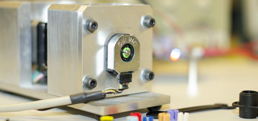
CUI Devices’ AMT31 and AMT33 series are an example of a state-of-the-art capacitive
encoder, providing A and B quadrature signals, an index signal, as well as U, V, and W
commutation-phase signals. Twenty-two selectable incremental resolutions between 48
to 4096 pulses per revolution (PPR) and seven motor pole-pairs from 2 to 20 are available.
The AMT31 and AMT33 series also feature easy installation, operate from a 5 V rail, and
require just 16 mA of supply current.
Page 4www.cuidevices.com
Designing Intelligence Into
Commutation Encoders
However, the benefits of the capacitive encoder go far beyond superior performance,
flexibility, and short- and long-term reliability. Unlike optical and magnetic encoders,
its digital-output side takes system design into the 21st century, offering many unique
system benefits in all phases of encoder use, from product development, to installation,
and even maintenance.
Why is this so? The output of the optical or magnetic encoder is functional but “dumb”, and
offers users no flexibility, insight, or operational advantages. In contrast, the capacitive
encoder is digitally based and uses a built-in ASIC and microcontroller to provide additional
features and enhanced performance. This smart output changes the user and performance
scenario in many ways, while still being 100% compatible with standard encoder outputs.
SUBSTANTIAL, BENEFICIAL CHANGE IS IN PLACE
Let’s look in more detail at the enhancements made possible by the ASIC and microcontroller
which are part of a capacitive encoder such as the CUI Devices AMT31 or AMT33 series:
● The digital nature of the CUI Devices capacitive encoder enables simple and quick “One
Touch” zeroing. The process is straightforward: lock the shaft to the desired position by
energizing the proper motor phases, and command the encoder to “zero” at this position;
the total time is just one to two minutes and no special instruments are needed.
In contrast, zeroing to mechanically align the commutation signals with the motor
windings using an optical or magnetic encoder is a multistep, complex, and often
frustrating process. It requires locking the rotor, physical alignment, and then back-
driving the motor while using an oscilloscope to observe the back EMF and encoder
waveforms for proper zero cross alignment. This is often an iterative process with the
steps usually needing to be repeated for fine-tuning and verification, so the entire cycle
can take 15 to 20 minutes.
● The digital features of the AMT series also greatly enhance the system design process,
providing flexibility, diagnostics and enabling assessment of the motor and motor-
controller performance. In particular, since a single capacitive encoder can support a
wide range of resolution and pole-pair values, designers can use this programmable-
resolution capability to dynamically adjust the response and performance of the PID
control loop during controller and algorithm development without having to purchase
and install an entirely new encoder.
Page 5www.cuidevices.com
Designing Intelligence Into
Commutation Encoders
The intelligence built into the AMT series also allows for on board diagnostics
for quicker field-failure analysis, an industry first. The encoder can be queried to
indicate if it is operating properly or if there is some sort of failure due to mechanical
misalignment on the shaft or other issues. Therefore, the designer can quickly
determine if the encoder is at fault and if not, look for the source of the problem
elsewhere, thus ruling out the encoder itself as possible problem. Furthermore,
engineers can use this feature for preventative measures - for example, executing an
“encoder good” test sequence before running the application. These capabilities, not
available in optical or mechanical encoders, allow designers to keep downtime to a
minimum while anticipating issues that might occur with units in the field.
● Finally the digital interface also simplifies the bill of materials (BOM). Since the encoder
can be tailored in software to the specific variation (PPR, pole pairs, and commutation
direction) needed, there’s no need to list and stock the different versions needed in a
multi-motor product, for multiple products, or in the installed location.
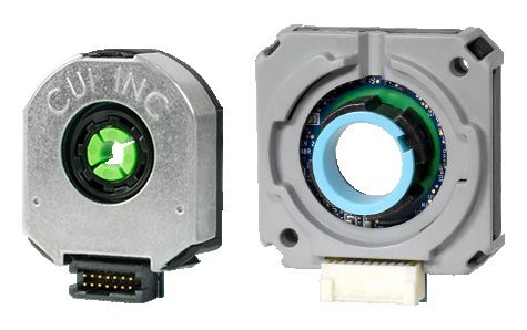
INTELLIGENT ENCODER PLUS GUI: POWERFUL
PAIRING
The Windows PC-based AMT Viewpoint™ software for CUI Devices capacitive encoders
speeds development, and also turns time-consuming mundane tasks, such as identifying
model number and version, into simple operations. It requires just a USB cable to interface
to the encoder, and implements a simple serial-data format. The GUI, Figure 4, allows the
user to tailor and customize the encoder to the application’s needs.
Figure 4:
CUI Devices’ AMT
Viewpoint software
provides an easy-
to-use development
interface
Page 6www.cuidevices.com
Designing Intelligence Into
Commutation Encoders
A settings screen in the GUI lets users see key encoder waveforms and timing, with
automatic adjustments as the encoder options are changed. Programming an encoder
through the GUI takes just a few keystrokes and about 30 seconds for the cycle to
complete. Most dramatic, the aligning and zeroing of an encoder for either A, B, index or
commutation mode takes only seconds, a sharp contrast to completing this task with a
non-programmable encoder.
SUMMARY
The benefits of encoders based on capacitive technology offer much more than just
improved performance and reliability. Encoders like CUI Devices’ AMT31 or AMT33,
with their built in ASIC/microcontroller, provide intelligent functionality supporting
programmable set-up and installation features, enabling operating insight and simplifying
inventory management. When these features are coupled with the PC-based GUI, they can
provide an easy-to-use yet sophisticated capability, which greatly simplifies all aspects of
encoder use from prototype design-in, evaluation, and debug through installation and
configuration, to diagnostics and inventory minimization. And all of this is at comparable
cost to other encoders, maintaining compatibility with standard outputs types and formats,
while also achieving lower power consumption. CUI Devices’ AMT commutation encoders
with their easy-to-fit adapters for different shaft sizes represent the logical next step in
leveraging the power of an intelligent interface to provide wide-ranging benefits that are
not available with other encoder technologies.
View CUI Devices’ AMT Commutation Encoders
LEARN MORE
Page 7 © 2021 CUI Devices. All rights reserved. 7/2021You can also read