DEVELOPMENT OF AN ALGORITHM FOR A LINEAR INTERPOLATION SYSTEM OF CNC MACHINES USING VARIABLES IN COMPASS 3D
←
→
Page content transcription
If your browser does not render page correctly, please read the page content below
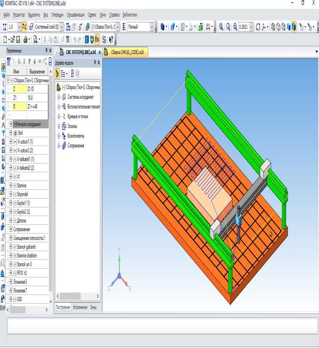
NOVATEUR PUBLICATIONS
 JournalNX- A Multidisciplinary Peer Reviewed Journal
 ISSN No: 2581 - 4230
 VOLUME 7, ISSUE 5, May. -2021
 DEVELOPMENT OF AN ALGORITHM FOR A LINEAR INTERPOLATION
 SYSTEM OF CNC MACHINES USING VARIABLES IN COMPASS 3D
 Gafurov B.X,
 Associate professor of Tashkent state technical university

 Khasanov O.A,
 Assistant teacher of Tashkent state technical university

 Baxronov Kh.B
 Master student of Tashkent state technical university

ABSTRACT: trajectory can be programmed and guided by
 In this paper, we have analyzed the conventional methods. will not happen.
system programming algorithm available in To do this, the nonlinear contours of the
the interpolator device used in CNC systems. workpiece are approximated, that is, the
Interpolation is a function of the nonlinear contour is replaced by other simpler
interpolator structure used to process geometric elements. Replacements are made
straight lines, circles, and parabolas. The with straight lines, arcs, circles, or parabola
CNC device cannot perform two motions at sections. For example, Figure 1 shows the
the same time and feels the need for approximation of the curve y = f (x) bounded by
interpolation when performing a shift along points 1 and 2 with the chord, intersection, and
a curved contour relative to any system line experiment lines. As a result of the
on its coordinate axis. Using the Compass 3D approximation, the curve bounded by points 1
program, we created a machine model and and 2 is replaced by straight lines 1-a-b-2
included system algorithms that perform forming broken lines, where the section "a - b"
interpolation. is called the approximation area.

INTRODUCTION:
 The control program's working frame
information is general in nature, meaning it
provides the coordinates of the end point of the
trajectory (in the absolute computational
system), or the distance the working body has to
travel (in the relative computational system). In
this case, the frame does not contain
information on how to perform the given
 a) b) v)
displacement, that is, how the CNC device
controls the thrust drives to ensure a given
 Figure 1. Approximation of nonlinear contours
displacement trajectory.
 a) with chordas; b) with intersecting lines; c)
 Because the coordinate system of CNC
 with test strips
machines is right-angled and the machine
 In this case, the approximation error is
guides are parallel to the coordinate axes, a
 measured with the bending arrow d, which in
curved (or inclined to the coordinate axes)
 turn is determined by the approximation step.
 155 | P a g e
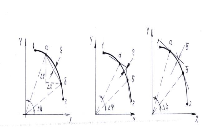
NOVATEUR PUBLICATIONS
 JournalNX- A Multidisciplinary Peer Reviewed Journal
 ISSN No: 2581 - 4230
 VOLUME 7, ISSUE 5, May. -2021
The approximation step depends on the value of and transmit information about these
the Δx and Δy coordinate small pushes or the coordinates to the control unit. consists of. The
central angle Δφ. To increase the accuracy of the function of the interpolator can also be
approximation, the length of the straight line expressed as: to provide a functional connection
sections should be reduced. between the coordinates of the base points
 The approximation step for the during the movement of one base point to
approximation methods is found in the another base point per minute, as well as to
following formulas: transmit signals about these coordinates to the
A) to approximate with chordas: ∆φ = control device.
 δ The function performed by the
2 arccos (1 − R)
 interpolator is called interpolation. Depending
B) to approximate with intersecting lines:
 R− δ on the approximation method, the interpolation
∆φ = 2 arccos (R+ δ) can be linear, circular, or parabola.
V) to approximate with attempt lines: ∆φ = The rule of interpolation implementation
 R
2 arccos (R+ δ) (interpolation algorithm) is mainly based on the
 solution of algebraic equations, relying on the
 In these formulas, R is the radius of the
 method of estimation function. In linear
arc, δ is the approximation error. The
 interpolation, the evaluation function for each
approximation step can also be specified with
 intermediate point of the trajectory can be
small shifts in ΔX va ΔY coordinates.
 expressed by the following formula:
As mentioned above, in order to bring the actual
 F i,j = yj xk − xi yk ,
trajectory closer to a given trajectory, it is
necessary to increase the number of In this case , are the coordinates of
intermediate points (or approximation fields), the intermediate point with respect to the
as well as to provide a sequence of coordinate beginning of the line section; , -
thrusts to the instrument between these points. coordinates of the end point of the line section;
 The addition of additional reference I, j is the number of elementary thrusts along the
points leads to a sharp increase in calculations “x” and “y” axes. The length of each elementary
and program size when creating a management slip (interpolation step) is equal to the
program. Therefore, in practice, a detailed discreteness of the CNCQ.
representation of the trajectory of the The rule of interpolation can be seen in the
instrument between two intermediate points is graph below
carried out using a special computing device - an
interpolator. Or, in other words, for the
approximation to take place, the motion must be
performed on the two coordinate axes at the
same time interval, and the trajectory of the
center of the instrument must correspond to the
"a - b" intersection. This requirement is met by Figure 2. Interpolation: a) linear interpolation;
a special device - an interpolator. b) circular interpolation
 An interpolator is a computational part As can be seen from the figure, the
of a numerical control device whose main straight line contour being processed by OA is
function is to continuously find the coordinates not parallel to the coordinate axes. This means
of a moving point on a line of approximation or that in order to form such a contour, there must
an analytic curve with a certain discreteness
 156 | P a g e
NOVATEUR PUBLICATIONS
 JournalNX- A Multidisciplinary Peer Reviewed Journal
 ISSN No: 2581 - 4230
 VOLUME 7, ISSUE 5, May. -2021
be an interpolation that provides a sequence of
step pushes along the X and Y coordinate axes.
The line OA drawn on the interpolation divides
the XY coordinate plane into two areas: 1) the
value of the evaluation function is positive at the
top of the line OA (Ϝ> 0), and 2) the function has
a negative value at the bottom (Ϝ
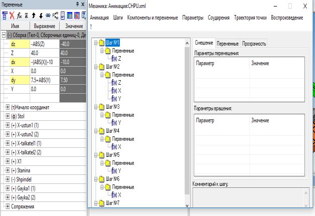
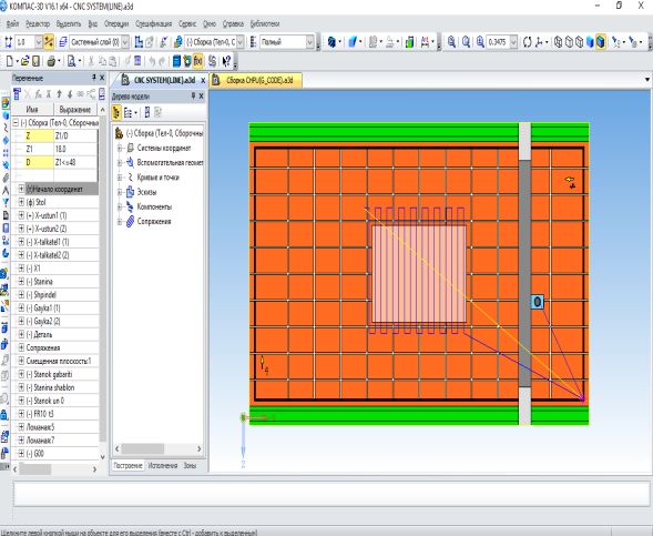
NOVATEUR PUBLICATIONS
 JournalNX- A Multidisciplinary Peer Reviewed Journal
 ISSN No: 2581 - 4230
 VOLUME 7, ISSUE 5, May. -2021
 We perform animation in the Compass Lubricoolant in machining process. IJAR,
3D program: 6(5), 347-352.
 6) Umarov, E. O., Mardonov, U. T., & Turonov,
 M. Z. (2021, January). MEASUREMENT OF
 DYNAMIC VISCOSITY COEFFICIENT OF
 FLUIDS. In Euro-Asia Conferences (Vol. 1, No.
 1, pp. 37-40).

 Figure 6. Animation sequence

CONCLUSION:
 In this paper, we performed the
interpolation operation used on CNC machines
using the Compass 3D program. We know that
modern production is impossible without CAD,
CAM, CAE technologies. However, the
capabilities of CAM technology in Compass 3D
are somewhat limited. We have shown that this
program can be used as well. We also created an
Interpolation Algorithm in the Java
programming language.

REFERENCES:
1) Molchanov G.N., Smetankin K.I. Stanki s ChPU.
 Strukturno-texnologicheskoe
 modelirovanie[CNC machines. Structural and
 technological modeling]. Tashkent,
 «Ukituvchi», 1993 – 240 s.
2) Acherkan N.S. i dr. Metallorejuщie stanki.
 Tom 2[Metal cutting machines. Volume 2], M.,
 «Mashinostroenie», 1965. – 628 str.
3) Push V.E. Konstruirovanie metallorejuщix
 stankov[Design of metal-cutting machine
 tools]. M., «Vыsshaya shkola», 1977 – 431 s.
4) Metallorejuщie stanki[Metal cutting
 machines]. Under edition of Tepinkichieva.
 M., «Mashinostroenie», 1973 – 431 s.
5) Odilovich, U. E., & Ugli, M. U. T. (2020).
 Analyzing the effect of magnetic field on
 158 | P a g e
You can also read