Development of an Omnidirectional Kick for a NAO Humanoid Robot
←
→
Page content transcription
If your browser does not render page correctly, please read the page content below
Development of an Omnidirectional Kick for a NAO
Humanoid Robot
Rui Ferreira1,2, Luís Paulo Reis1,4, António Paulo Moreira3,5, Nuno Lau2,6
1
LIACC – Artificial Intelligence and Computer Science Lab., University of Porto, Portugal
2
IEETA – Institute of Electronics and Telematics Engineering of Aveiro, Portugal
3
INESC-TEC – Institute for Systems and Computer Engineering of Porto, Portugal
4
DSI/School of Engineering, University of Minho, Portugal
5
DEEC/FEUP – Department of Electrical and Computer Engineering, Faculty of Engineering
of the University of Porto, Portugal
6
DETI/UA – Electronics, Telecommunications and Informatics Department, University of
Aveiro, Portugal
rui.ferreira@fe.up.pt, lpreis@dsi.uminho.pt, amoreira@fe.up.pt,
nunolau@ua.pt
Abstract. This paper proposes a method to develop an omnidirectional kick be-
havior for a humanoid robot. The objective is to provide a humanoid with the
ability to kick in different directions and to make kicks look more like those of
a human player. This method uses a Path Planning module to create the trajec-
tory that the foot must follow to propel the ball in the intended direction. Two
additional modules are required when performing the movement: the Inverse
Kinematics module computes the value of the joints to place the foot at a given
position and the Stability module is responsible for the robot’s stability. Simula-
tion tests were performed using different ball positions, relative to the robot's
orientation, and for various ball directions. The obtained results show the use-
fulness of the approach since the behavior performs accurately the intended mo-
tion and is able to kick the ball in all the desired directions.
Keywords: Robotics, Robotic Behaviors, Autonomous Agents, Human Behav-
iors, Robotic Soccer.
1 Introduction
Robotic soccer has been an area of constant evolution and of major driving for the
development of Artificial Intelligence and Intelligent Robotics [1]. Being soccer a
complex game where the environment is dynamic and in real time, it raises exciting
challenges and covers a wide area of research, from which stands out research in ro-
botics, physics, biology, electronics, computer science and mechanics. Fig. 1 shows
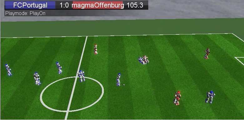
two teams of robots playing a simulated soccer.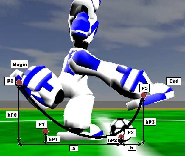
Fig. 1. Robots playing simulated 3d soccer.

   This work is related to the development of a new human like behavior for a hu-
manoid robot for Portuguese soccer team FC Portugal, to equip a robot with the abil-
ity to kick a ball in various directions. The need to create this behavior arises from the
necessity to perform a kick or a pass without having a preparation phase (phase used
to put the robot at a precise position to perform the old front/side kick), during which
the ball can be intercepted by an opponent.
   This behavior will be added to the list of all others previously developed in [2-3]
and enable a team of robots (NAO robots from Aldebaran), real or virtual ones, capa-
ble of playing a soccer match at RoboCup 3D Simulation League and Standard Plat-
form League, using similar rules to real soccer, following the strategic framework
previously developed in several related works [4-8].
   Section 2 describes the implementation of the kick behavior as well as its constitu-
ent modules, section 3 contains the practical results and experiments on the behavior,
and finally, section 4 gives the conclusions and presents some future work.

2      Omnidirectional Kick Development

2.1    Omnidirectional Kick
In general, kick behavior development is based on the use of keyframes for defining
the trajectory of the foot. This method defines motion as a series of static values for
the joints and then interpolates them sequentially to perform the movement. The main
disadvantages of this approach are the inflexibility and the need of a preparation
phase, in which the robot positions itself in order to kick the ball forward in the de-
sired direction.
   The idea of developing an omnidirectional kick is to make the kick more flexible
and to kick the ball in any direction. To perform this, the robot has to compute the
trajectory in real time and then make the foot follow this trajectory and propel the ball
in the intended direction. If, during the movement, the ball position changes, the tra-
jectory is updated
               dated and the foot movement adapts to this change,, but only if the ball is
still reachable by the foot.
    The omnidirectional kick behavior con-co
sists mainly of three modules: Inverse Kin-
                                          K
ematics module, ule, Path Planning module and
Stability module.ule. The Inverse Kinematics
                                   K
module is responsible for calculating the
value of the joints of the leg that will per-
                                           pe
form the kick, the Path Planning
                            P       module is
responsible to compute a trajectory for the
foot to propel a ball in some direction and
the Stability
       tability module is responsible
                           respo      to stabi-
lize the robot while performing the move-
                                        mov
ment.
    Fig. 2 shows some of the parameters re-
quired to develop the movement. A descrip-
tion of all used parameters can be seen in
Table 1.                                        Fig. 2. Parameters used to create the
                                                   movement.
         Table 1. Parameters description.

       Parameter                                      Description
          a                                 Distance from ball to curve start
          b                                 Distance from ball to curve end
         hP0
         hP1                  Bézier cubic curve parameters (height coordinate only).
         hP2                   Useful to shape the curve and try different kicks)
         hP3
       Duration                      Duration of the kicking phase (see Fig. 3)
                              Angle between foot orientation and vector Ball2Target.
    footOrientation       This parameter is important to kick with different sections of
                                  the foot, e.g. front, side (inner/outer) or heel.

  The behavior is divided into a computational part, in which all the computations
needed to perform the movement are made, and an execution part, in which the actual
movement is performed. Execution part consists of five phases:

• Lean_Phase – This is when the robot shifts is center of mass onto support leg.
• Raise_Phase – Phase where the robot raises the kick foot off the ground.
• Kick_Phase – When the robot kicks the ball. This is the main phase.
• Return_Phase – Phasehase when the
                                  t robots returns it’ss kick leg to the base position,
  without putting the foot on the ground.
• UnRaise_Phase – This is when the robot shifts is center of mass to both legs while
  putting the kick foot on the ground.
Fig. 3 shows the building blocks of the behavior as well as the connections be-
tween them, inputs, outputs and generated data.
Fig. 3. Building blocks of the developed behavior.
2.2 Inverse Kinematics Module
The Inverse Kinematics problem is to determine the value of each joint in order to put
a part of our object at a given location in space. Some mechanical characteristics as-
sociated with our object, such as the number of joints, joints rotation/translation lim-
its, can make the calculation complex and often raise difficulties to obtain a unique
solution [9]. In this study we used a method adapted from [10] in which the geometric
approach method was used to determine each joint from the leg of the robot NAO.
Two mechanical problems make the solving of Inverse Kinematics complicated:
• The axes of the hip yaw are rotated by 45 degrees;
• The hip yaw axes of each leg are mechanically connected.
The input data is a homogeneous transformation matrix that contains the position
and orientation of the desired foot target relative to a frame located at the robot pelvis.
Pelvis
This matrix is represented by H Foot . Next we have to determine the foot relative to
the hip rotated frame [6].
HipRot
H Foot = Rot x (π 4) ⋅ Trans y (l dist 2) ⋅ H Foot
Pelvis 1
(1)
1
RotK(v) and TransK(v) represents rotation and translation of value v along axis K, respec-
tively, and l legs = distance between legs.Assuming a triangle formed by the robot’s thigh (lthigh) and lower leg (llowerleg),
HipRot
and the translational vector of H Foot (ltrans), and using law of cosines and atan2(),
we can determine the value of the knee and ankle joints [6].
The pitch, roll and yaw of the hip are determined by simple manipulation of the el-
Thigh
ements of H HipRot as seen in (2).
( ) ( )
HipRot = Rotz θ hipYaw ⋅ Rot x θ hipRoll ⋅ Rot y θ hipPitch
HThigh ( )
c yc z − s x s ys z − c x s z c zs y + c ys x s z
2
(2)
= c zs x s y + c ys z c x c z − c yc zs x + s ys z
− cx c y sx cxcy
Thigh
and H HipRot can be determined using
(
HipRot = H Thigh
H Thigh Foot
) ⋅ (H
−1 HipRot −1
Foot ) (3)
Foot
H Thigh = Rot x (θ ankleRoll ) ⋅ Rot y (θ anklePitch ) ⋅
( )
Trans z l lowerleg ⋅ Rot y (θ knee ) ⋅ Trans z l thigh ( ) (4)
2.3 Path Planning Module
This module is responsible for creating a trajectory for the foot to follow in order to
impose a motion to the ball in the desired direction. It makes use of Bézier curves [11]
to determine a path between two points. These type of curves are defined as paramet-
ric curves and is easy to determine any point of the curve without using complex math
(a simple equation gives the point). For our study we used a Bézier cubic curve (n=3)
and the point can be determined using (5).
n
n i
b(t ) = ⋅ t ⋅ (1 − t )n −1 ⋅ p i , t ∈ [0,1]
∑ (5)
i
i =0
2.4 Stability Module.
The Stability module uses the center of mass equation [12] to determine if the ground
projection of the center of mass (GCoM) is actually inside the polygon of the support
foot. If not, it enters in a cycle where it will open one arm (on the same side of the
supporting foot) until GCoM is in the desired location. In the extreme case where the
arm movement is not enough a change in the hip and ankle roll angles of the support-
ing foot is also made to tilt the robot to a stable position.
2
cx, cy, cz represents cos( θ hipRoll), cos( θ hipPitch), cos( θ hipYaw), respectively.3 Experiments and Results
In this section we show the results of several experiments
performed to verify analytically the success of this work. We
start by testing each module individually and then test the
whole behavior. The tests to each individual module are of
great importance since the final behavior depends strongly of
their success.
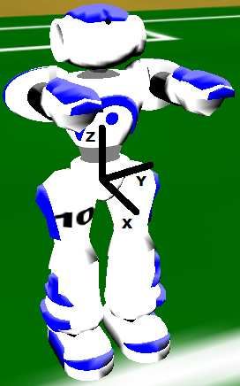
All points representing positions in the individual module
tests are relative to a frame located at the robot pelvis (see Fig.
4).
Fig. 4. Reference
frame.
3.1 Inverse Kinematics Module Tests
The main objective when testing this module is to verify its functionalities and limita-
tions. It is necessary for it to operate with the minimum error possible because it is the
base of the motion. A small error when computing the joints values makes the foot
perform a wrong trajectory and propel the ball in the wrong direction. Table 2 shows
the results of this test.
Table 2. Results of the Inverse Kinematics module tests.
Target Average Standard Deviation Average-Target
(x, y, z) (mm) (x, y, z) (mm) (x, y, z) (mm) (x, y, z) (mm)
(0, -55, -150) (3, -56, -148) (1, 1, 3) (3, -1, 2)
(-100, -55, -100) (-89, -60, -99) (1, 1, 0) (11, -5, 1)
(100, -55, -100) (100, -55, -105) (7, 1, 3) (0, 0, -5)
(0, -100, -100) (7, -104, -108) (2, 3, 3) (7, -4, -8)
(500, -55, -10) (214, -54, -16) (1, 1, 2) (-286, 1, -6)
3.2 Path Planning Module Tests
The main purpose when testing this module is to verify its trajectories creation. It is
also necessary for it to operate with the minimum error possible because if the trajec-
tory is miscalculated we will get a wrong movement, resulting in a wrong ball motion.
Fig. 5 shows 3 curves (linear, quadratic and cubic) created and the ability of the
foot to follow these curves.Fig. 5. Various curves created by Path Planning module and the trajectory executed by the foot. 3.3 Omnidirectional Kick Tests For the tests of the complete behavior we will test for: ─ 3 positions (#1, #2 and #3) of the ball relative to the robot orientation (see Fig. 6); ─ 5 kick directions (-90, -45, 0, 45 and 90 degrees), when possible. Fig. 6. Ball Positions for the tests. Left is 'Position #1', center ‘Position #2’ and right is 'Position #3' For each direction we performed the movement 10 times and 10 samples of the fi- nal ball position. We proceeded to get the average and standard deviation of the 10 samples and in the end we determined the resulting direction. This data is shown in Table 3 and Fig. 7.
Table 3. Results from the performed tests.
                                         -90        -45          0            45       90
                                        (x, y)     (x, y)      (x, y)        (x, y)   (x, y)
                 Average (mm)       (24, -1009) (719, -678) (975, -2) (701, 681) (31, 962)
     Pos.
      #1

            Standard Deviation (mm)   (17, 38)    (37, 34)    (37, 22)  (23, 43)  (16, 45)
                  Direction (º)        -88.60      -43.32       -0.15    44.18     88.12
                 Average (mm)        (13, -989) (758, -741) (1082, 2) (721, 676) (31, 997)
     Pos.
      #2

            Standard Deviation (mm)    (7, 21)    (41, 40)     (44, 4)  (31, 40)  (26, 36)
                  Direction (º)        -89.20      -44.37        0.12    43.15     88.19
                 Average (mm)        (11, -991) (693, -697) (1053, -29)
     Pos.
      #3

            Standard Deviation (mm)    (3, 23)    (22, 22)    (34, 18)
                  Direction (º)        -89.35      -45.15       -1.59

                     Fig. 7. Samples location for Positions #1, #2 and #3.

   By examining the results obtained from this test we can see that the behavior can
perform the movement and propel the ball in various directions. From the table we
can see the average final position of the ball of the 10 samples as well as the standard
deviation, and from the average we determined the direction. The determined direc-
tion value, of each direction, only differs a few degrees from the intended target direc-
tion, which confirms the accuracy propelling the ball. The accompanying graphic
serves only to have a visualization of the ball’s final position of the 10 samples for
each target direction. The samples are grouped by target direction. The parameters
used on these tests were hand tuned. We can control the kick power by adjusting both
the kick duration and the initial and final position.
To test the sensibility of the kick against different positions of the ball, relative to the robot, another test was made. This test consists of kicking the ball with a desired direction, using always the same values for the parameters, and only changing the ball initial position. The results obtained are shown in Fig. 8, where it is represented the distance and direction of the ball with a gradient value and the (x, y) coordinates refers to the ball’s initial position relative to the kick foot. Fig. 8. Differences on the distance and direction due to different ball positions, for the same kick (forward kick, direction=0º). The conclusion we take from these tests is that: if we configure the parameters of the behavior with some accuracy, we can get very good results. The problem is that, sometimes, it is not so easy to get the best parameters, becoming necessary the use of optimizers. From Fig. 8 we can see that, if the ball is within a certain area relative to the kick foot, in almost 80% of that area it can kick the ball without losing accuracy. 4 Conclusions and Future Work In this study we developed a behavior in order to provide a humanoid robot with the ability to perform an omnidirectional kick. The modularity of this behavior makes it perfect for future improvements or modifications. The results obtained proved that the behavior performs accurately the desired mo- tion. The Inverse Kinematics module, being the base of the behavior and with errors in the order of millimeters, is responsible for these satisfactory results. If it was not for the joints limitations it could reach any point within the working volume. The Path Planning module proved to be very valuable when creating trajectories. With it, one can calculate any kind of trajectory easily, quickly and accurately.
Future work will be focused on improving the behavior, by optimizing it in order
to perform faster and to drive the ball farther. This will be based on previous work
developed on the area of machine learning and optimization applied to robotic soccer
[13-16]. It will also be interesting to expand the behavior to perform heel kicks and to
incorporate the kick in a walk/run motion.

References
 1. Hiroaki Kitano, Minoru Asada, Yasuo Kuniyoshi, Itsuki Noda, Eiichi Osawa, and Hitoshi
    Matsubara. RoboCup: A challenge problem for AI and robotics. In H. Kitano, editor,
    RoboCup, volume 1395, LNCS, pages 1-19. Springer, 1997.
 2. Nima Shafii, Luis Paulo Reis, Nuno Lau, Biped walking using coronal and sagittal move-
    ments based on truncated Fourier series, (2011) Springer LNCS, 6556, pp. 324-335.
 3. Edgar Domingues, Nuno Lau, Bruno Pimentel, Nima Shafii, Luis Paulo Reis, A.J.Neves,
    Humanoid behaviors: From simulation to a real robot (2011), 7026 LNAI, pp. 352-364.
 4. Luis Paulo Reis, Nuno Lau, E. Oliveira, Situation Based Strategic Positioning for Coordi-
    nating a Team of Homogeneous Agents, Springer LNAI, Vol. 2103, pp. 175-197, 2001
 5. Nuno Lau, Luis Paulo Reis, FC Portugal - High-level Coordination Methodologies in Soc-
    cer Robotics, Robotic Soccer, Book edited by Pedro Lima, Itech Education and Publishing,
    Vienna, Austria, pp. 167-192, December 2007, ISBN 978-3-902613-21-9
 6. Nuno Lau, Luís Paulo Reis, João Certo, Understanding Dynamic Agent’s Reasoning, 13th
    EPIA 2007, , Portugal, Dec 3-6, 2007, Springer LCNS, Vol. 4874, pp. 542-551, 2007
 7. Fernando Almeida, Nuno Lau and Luis Paulo Reis, A Survey on Coordination Techniques
    for Simulated Robotic Soccer Teams, MAS&S@MALLOW2010, Lyon, France, Sep2010
 8. Luis Mota, Luís Paulo Reis, Nuno Lau, Multi-Robot Coordination using Setplays in the
    Middle-size and Simulation Leagues, Mechatronics, Elsevier, Vol. 21, Issue 2, pp. 434-
    444, March 2011
 9. A. A. Goldenber, B. Benhabib, and R. G. Fenton. A complete generalized solution to the
    inverse kinematics of robots. IEEE J. Robotics and Automation, RA-1(1):14-20, 1985.
10. B-Human team. B-human: Team report and code release 2011. Chapter 5. Available in
    http://www.b-human.de/downloads/bhuman11_coderelease.pdf, accessed February 2012.
11. Thomas       Sederberg.     Byu      bézier    curves.   Chapter    2.    Available    in
    http://www.tsplines.com/resources/class_notes/Bezier_curves.pdf, accessed Feb 2012.
12. Paul A. Tipler and Gene Mosca. Physics for Scientists and Engineers Extended Version.
    W. H. Freeman, fifth edition, August 2003.
13. Pedro H. Abreu, J.Moura, Daniel C. Silva, Luís Paulo Reis, Júlio Garganta, Performance
    Analysis in Soccer: a Cartesian Coordinates based Approach using RoboCup Data, Soft
    Computing, Springer, Vol. 16, pp. 47–61, ISSN: 1432-7643, January 2012
14. Brigida Mónica Faria, Luis Paulo Reis, Nuno Lau, G. Castillo, Machine Learning Algo-
    rithms applied to the Classification of Robotic Soccer Formations and Opponent Teams, In
    Proceedings of the 2010 IEEE CIS 2010, June 28–30 2010, Singapore (pp. 344-349)
15. Rui Almeida, Luís Paulo Reis, Alípio M. Jorge, Analysis and Forecast of Team Formation
    in the Simulated Robotic Soccer Domain. in 14th EPIA'2009, Aveiro, LNAI 5816, Spring-
    er, pp. 239-250, October 12-15, 2009
16. Hugo Picado, Marcos Gestal, Nuno Lau, Luís Paulo Reis, Ana Maria Tomé, Automatic
    Generation of Biped Walk Behavior Using Genetic Algorithms. 10th IWANN 2009,
    Springer, LNCS Vol. 5517, pp. 805-812, Salamanca, Spain, June 10-12, 2009
You can also read