MOF-DERIVED POROUS NIO NANOROD AND MICROFLOWER STRUCTURES WITH ENHANCED NON-ENZYMATIC GLUCOSE ELECTROCHEMICAL SENSING PERFORMANCE
←
→
Page content transcription
If your browser does not render page correctly, please read the page content below
Int. J. Electrochem. Sci., 16 (2021) Article ID: 210465, doi: 10.20964/2021.04.65

                                                                          International Journal of
                                                                          ELECTROCHEMICAL
                                                                                  SCIENCE
                                                                                 www.electrochemsci.org

MOF-derived Porous NiO Nanorod and Microflower Structures
with Enhanced Non-enzymatic Glucose Electrochemical Sensing
Performance
Xiaobei Zhang1, Rui Wang2, Yaqing Wei2, Xiaoqi Pei2, Zhuo Zhou2, Jingchao Zhang2,
Renchun Zhang2, Daojun Zhang2,*
1
  College of Chemistry, Zhengzhou University, 100 Science Road, Zhengzhou 450001, P. R. China
2
  Henan Key Laboratory of New Optoelectronic Functional Materials, College of Chemistry and
Chemical Engineering, Anyang Normal University, Anyang 455000, Henan, China
*
  E-mail: zhangdj0410@sohu.com, zjc19830618@126.com

Received: 5 December 2020 / Accepted: 8 February 2021 / Published: 28 February 2021

The porous and hierarchical structure with plentiful electroactive sites may ensure high activity and
stability in electrocatalytic oxidation glucose by accelerating the transport of analyzer and electron
during the electrochemical process. Thus, to design and fabricate electrode materials with different
structures and morphology is still an appreciation method to promote electrochemical performance. In
this work, two morphology of porous NiO structures were synthesized by the MOF-derived precursors
after the calcination process. The obtained NiO structures prepared by thermal conversion of Ni-BTEC
and Ni-PTA frameworks at mild temperature conditions not only possess the nanorods and microflowers
morphology of the MOF precursors but also exhibit large surface area, which could be used as the
enzyme-free catalyst for glucose electrooxidation in the basic supporting electrolyte. The result indicates
that MOF-derived porous NiO nanorods and microflowers may be potential electrode materials for
glucose electrochemical sensing.

Keywords: porous NiO structure; nanorods; microflowers; enzyme-free glucose sensor; electrocatalysts

1. INTRODUCTION

        In recent years, electrochemical sensors based on transition metal compounds has received
widespread interest due to their low cost and easy preparation [1-3]. Using abundant elements on earth
instead of noble metal to fabricate electrode materials is appreciated. To date, a great deal of transition
metal oxides (TMOs) such as NiO [4, 5], CuO [6,7], Co3O4 [8, 9], CuCo2O4 [10], and NiCo2O4 [11,12]
micro/nanostructures have been investigated as electrode materials for electrochemical sensing. Many
factors of modified electrode materials include surface morphology, microstructure and composition can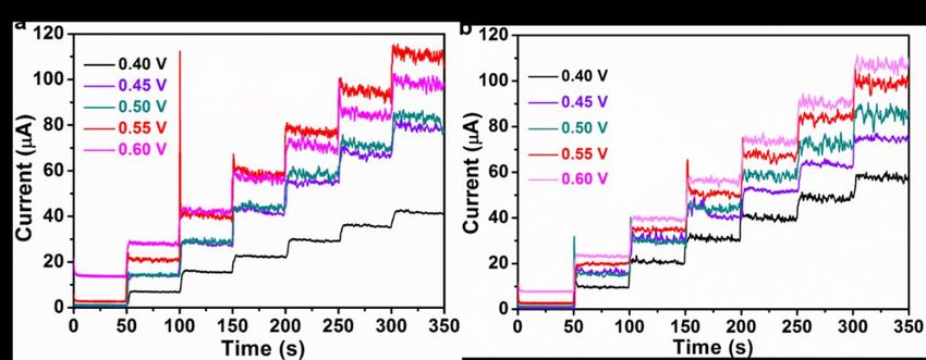
Int. J. Electrochem. Sci., 16 (2021) Article ID: 210465                                                   2

affect the electrochemical sensing performances. Porous micro/nanostructures have attracted great
attention in nonenzymatic electrochemical sensing consist of glucose, hydrogen peroxide, hydrazine,
glutathione, dopamine, and etc.
        The glucose level in the blood can reflect and management of the diabetes signal of the people,
thus the fast and accurate detection of glucose concentration is an important research topic [13]. In recent
years, the non-enzymatic electrochemical glucose sensor based on TMOs have been recognized as the
preferable candidate due to their inherent stability and good performance. Fabricating micro/
nanostructures with controllable morphology is available to tune the specific surface area of the electrode
materials, which will facilitate the glucose electro-oxidation kinetics. In recent years, porous micro/
nano-materials achieved from the transformation of metal-organic frameworks (MOFs) precursors
usually exhibited excellent performance in electrocatalysts, supercapacitors, and chemical sensors
[14,15]. The micro/nano-structure derived from MOFs provides a large surface area and connected
porous architecture for the charge transfer and the diffusion of electrolyte and analyte within the
electrode, which facilitate the kinetic-controlled electrochemical glucose oxidation processes. Nickel
oxides are more stable in an alkaline environment than sulfides, however, the common nickel oxides
nano-catalysts are easy to aggregate on the surface of the electrode, leading to weakening
electrochemical performance. NiO structures derived from MOFs can keep the skeleton of parent
precursors without agglomeration, providing abundant surface area and inner space for glucose detection
and electron transport [16,17]. Furthermore, the design and synthesis of NiO nanostructure avoid the use
of additional template, such as Cu2O nanospheres [18] and carbon microspheres [19], thus the obtain
morphology of NiO is rich and more variable. Taking into account the above reasons, in this work, we
utilize a self-sacrificial template strategy based on direct annealing Ni-MOF precursors at middle
temperature to prepare porous NiO nanorods and microflowers, the as-obtained porous NiO structures
preserve the original Ni-MOF morphology well. Further research manifests that NiO nanorods and
microflowers modified glass carbon electrodes exhibit superior performance in detecting glucose and
may act as potential enzyme-free glucose sensors in the future.

2. EXPERIMENTAL SECTION

2.1 Synthesis of NiO porous nanorods

        First, nickel (II) 2,4-pentanedionate (0.5g, 1.95 mmol) and pyromellitic acid (H4btec) (0.5g, 1.97
mmol) were dispersed in 5.0 mL of N-N-dimethylformamide (DMF), 5.0 mL of ethanol, and 5.0 mL of
H2O with vigorous stirring for about 20 min, then heated at 160 oC in oven for 12 h. The obtained green
powder was isolated via centrifugation and washed by ethanol/H2O (v/v=1:1) three times, then heated
to 400 °C in muffle furnace at a heating rate of 2 °C min−1 and kept for 2 h under atmosphere.

2.2 Synthesis of NiO porous microflowers

       Nickel nitrate hexahydrate (0.0291g, 0.1 mmol) and p-phthalic acid (PTA) (0.0166g, 0.1 mmol)
were dissolved in the mixture solution of N-N-dimethylacetamide (DMA, 3.6 mL) and alcohol (2.4 mL)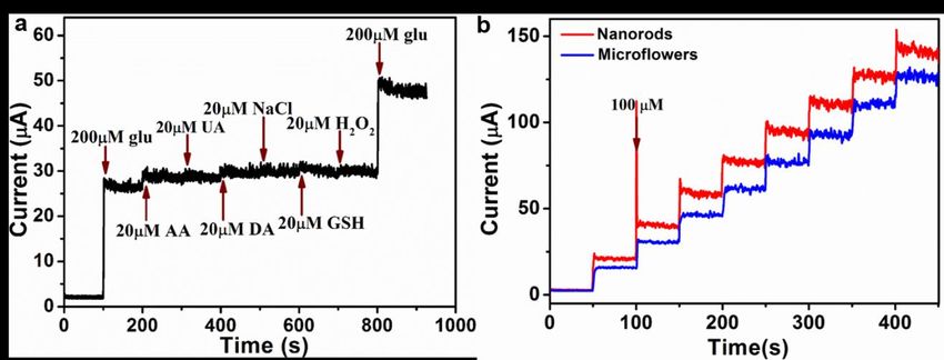
Int. J. Electrochem. Sci., 16 (2021) Article ID: 210465                                               3

under continues stirring at room temperature for 30 min, and then kept in 140 oC for 4 h. The obtained
sample (Ni-PTA MOF) were centrifuged by ethanol and deionized water (v/v=1:1), and dried at 60 oC.
The NiO microflowers was prepared by the same sintering process as above mentioned.

2.3 Preparation and measurement of glucose sensor electrodes

        1.0 mg of the above two kinds of NiO catalysts was dispersed to 1.0 mL ultrapure water under
sonication, respectively. After that, 5.0 μL of the catalyst inks were dropped on burnished GC electrode
(3 mm) and dried at room temperature naturally. The electrochemical glucose detection was researched
in a three-electrode setup by using Ag/AgCl as the reference electrode, platinum wire as the counter
electrode, and NiO modified GC electrode as the working electrode. All the electrochemical experiments
were conducted at room temperature under mild stirring.

3. RESULTS AND DISCUSSION

Figure 1. (a-b) The FESEM images of the Ni-BTEC MOF precursors, (c-d) the NiO nanorods derived
       from Ni-BTEC MOF after calcination.

        The SEM images of the as-prepared Ni-BTEC MOF precursors before and after calcination are
shown in Fig.1. The Ni-BTEC MOF nanorods are smooth and well-distributed, the morphology can be
retained after calcination but the surface seems rough and porous. Through statistics of one hundred
particles, the average size of the Ni-BTEC MOF-derived NiO nanorods is approximately 500 nm in
length and 100 nm in width. The derived NiO nanorods maintain the initial precursor morphology well
with dimension shrinkage, however, after calcination, the obtained particles exhibited enriched porous
architecture, which was observed in TEM images (Fig.2a-c), suggests potential good properties. The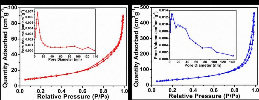
Int. J. Electrochem. Sci., 16 (2021) Article ID: 210465                                      4

HRTEM image of the NiO nanorod indicates the presence of clear lattice fringes, and the lattice
interplanar space of 0.245 nm corresponds to the (111) crystal plane of NiO (Fig.2d).

Figure 2. (a-b) TEM images of the NiO nanorods derived from Ni-BTEC MOF, (c-d) HRTEM image of
       NiO nanorods.

Figure 3. (a-b) SEM images of Ni-PTA MOF precursors, (c-d) The NiO microflowers obtained from
       the annealed Ni-PTA MOF.

       As shown in Fig.3a-b, the Ni-PTA MOF microflowers was assembled by numberless ultrathin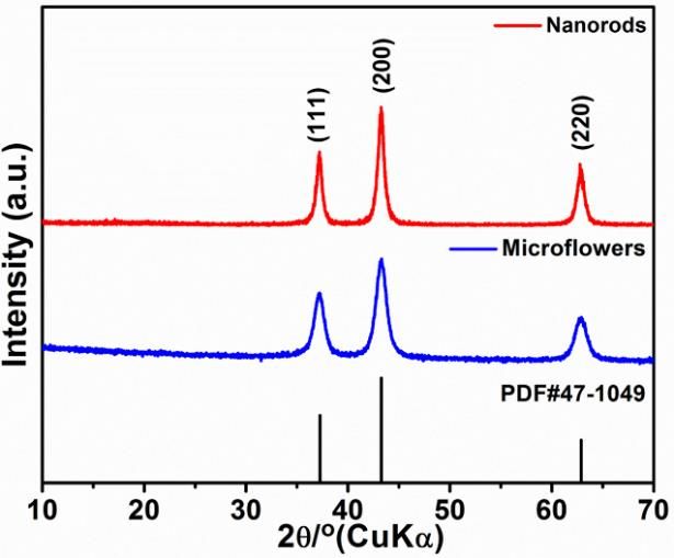
Int. J. Electrochem. Sci., 16 (2021) Article ID: 210465                                                  5

nanosheets, the morphology can be retained after calcination, but the aggregation degree of nanosheets
increase and become fragile (Fig.3c-d). In the TEM image shown in Fig.4a-c, the NiO microflowers
contains numbers of nanoparticles, the lattice spacing of the NiO microflowers corresponds to the (111)
plane of NiO (Fig.4d), indicating the calcined product was pure NiO.

Figure 4. (a-c) TEM images of the NiO microflowers derived from Ni-PTA MOF, (d) HRTEM image
       of NiO microflowers.

        The crystal structures of the as-synthesized samples were analyzed by the XRD technique and
the XRD patterns were shown in Fig.5. The characteristic diffraction peaks present in the pattern at 37.25,
43.28, and 62.88°, can be indexed to the (111), (200), and (220) crystal face of NiO (JCPDS 47-1049).
Compared with the XRD pattern of NiO nanorods obtained from Ni-BTEC, the wide diffraction peaks
of NiO nanosheet-assembled microflowers indicated the little crystal size of NiO acquired from Ni-PTA
MOF.

                      Figure 5. XRD patterns of NiO nanorods and microflowers.
Int. J. Electrochem. Sci., 16 (2021) Article ID: 210465 6
The Brunauer-Emmet-Teller (BET) specific surface area of NiO nanorods and microflowers
obtained from N2 sorption isotherms, the typical hysteresis loop at the middle-pressure region was
ascribed to the type IV isotherm, indicating the as-synthesized samples show a typical mesoporous
structure. The BET surface area of NiO nanorods and microflowers is 38.25 and 123.49 m2 g-1,
respectively, with an average pore diameter of ~3.6 and 4.5 nm (inset in Fig.6a-b). The relatively high
surface area and mesoporous architecture not only can provide efficient active sites but also promote the
mass and electron transfer kinetics.
Figure 6. The N2 sorption isotherms and pore size distribution of (a) NiO nanorods and (b) NiO
microflowers.
3.1. Nonenzymatic-glucose sensor based on porous NiO nanorods and microflowers
The electrochemical performances of the porous NiO nanorods and microflowers were
conducted in a typical three-electrode system in 0.1 M NaOH solution. At first, cyclic voltammogram
(CV) measurements for NiO electrodes were conducted with the absence and presence of 0.1-2.0 mM
glucose at a sweep of 50 mVs−1 (Fig.7a-b). There is a distinct redox peak in each CV curve, which may
attribute to the Faradaic oxidation/reduction reaction of Ni2+ (NiO) and Ni3+ (NiOOH) on the electrode
surface. Upon injection of glucose, the porous NiO nanorods electrode demonstrates obvious a pair redox
peak at ~0.36/0.53V, the oxidation currents of glucose show a steady increase with the boost glucose
concentration and the anodic peak position upshift slightly. On the contrary, an obvious positive shift of
the oxidation peak of NiO flowers with an increase in glucose concentration can be observed in Fig.7b,
which indicated the decreases of glucose oxidation kinetics due to the oxidation of glucose molecules
and some oxidized intermediates absorbed on the active sites, which cause the local pH change at the
surface of NiO microflowers modified electrode [20, 21]. Thus, compared to NiO microflowers electrode,
the porous NiO nanorods electrode may be an ideal glucose sensing materials. The anodic peak current
of the two electrodes increases linearly with the addition of glucose, and the enhancement of anodic
current may attribute to irreversible oxidation of glucose with the NiO catalysts. Simultaneously, the
cathodic peak current of the two electrodes decrease due to the little consumption of Ni3+ during the
glucose electro-oxidation process [22]. The possible mechanism for glucose oxidation is illustrated as
follows [23-26]:
NiO + OH–→ NiOOH + e–Int. J. Electrochem. Sci., 16 (2021) Article ID: 210465 7
NiOOH + glucose → Ni(OH)2 + H2O + glucolactone
In order to discover the relationship between the applied potential and the performance of the
two sensors, the optimum operating potential was investigated in the presence of 0.1 mM glucose. The
current response curves for different applied potentials shown in Fig.S1, 0.55 V was chosen as the
applied potential for enzyme-free glucose determination, which is lower than NiO nanofibers obtained
by electrospinning and calcination process [27], NiO coated carbon nanotubes (NiO/SCCNTs)
synthesized by atomic layer deposition method [20], Ni-MOF/Ni/NiO/C nanocomposite obtained by one
step calcination method [25].
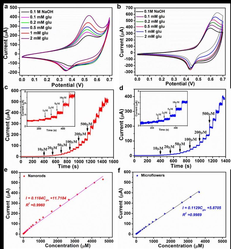
Figure 7. The cyclic voltammograms of NiO (a) nanorods and (b) microflowers in 0.1 M NaOH with
different concentration of glucose. The chronoamperometry curves of NiO (c) nanorods and (d)
microflowers at 0.55V vs. Ag/AgCl. The plots of response current density vs. glucose
concentration (e) NiO nanorods and (f) NiO microflowers.
The glucose sensing performance of the two modified electrodes was evaluated via amperometric
curve (i–t). Fig.7c-d show the representative amperometric response of NiO-GCE upon continuous
injection of glucose into a stirring supporting electrolyte at a potential of 0.55 V. The response current
increased sharply and rapidly to reach a stable platform when glucose was injected into the stirring
electrolyte solution, suggesting a fast electron transfer rate between analyzer and NiO-GCE. As shownInt. J. Electrochem. Sci., 16 (2021) Article ID: 210465 8
in Fig. 7e, for the NiO nanorods electrode, the response current and glucose concentration can give a
good linear relationship in a wide linear range of 0.0018 to 4.65 mM, which is superior to that of NiO
microflowers electrode with the liner range of 0.0018 to 3.65 mM (Fig. 7f). The acquired linear equation
of the former and the latter is I (µA) = 0.1184C (µM) +11.7184 (R2=0.9960) and I (µA) = 0.1129C (µM)
+5.8705 (R2=0.9989), respectively. Furthermore, the low detection limit of NiO nanorods and
microflowers electrode is calculated as 0.7 and 0.8 μM (3σ/s), respectively, and the corresponding
sensitivity of the two NiO electrodes is 1.6775 and 1.5989 µA µM-1 cm-2.
Table 1. The comparison of performances with other related sensors.
Electrode material Potential Linear Detection Sensitivity/µA Reference
(V) range/mM limit/μM mM−1cm−2
0.55 0.0018-3.65 0.8 1598.9 This
NiO microflowers
work
0.55 0.0018-4.65 0.7 1677.5 This
NiO nanorods
work
0.55 0.1-0.3 0.6 1917 18
NiCo2O4 a
0.3-2.24 703
NiO hollow 0.35 1.5-7.0 47 343 19
Nanospheres b
NiO/SCCNTs c 0.65 0.002-2.2 0.1 1252.3 20
Ni(OH)2/3DGF d 0.55 0.001-1.7 0.34 2650 21
s-NiO/GD e 0.5 Up to 10 0.9 3613 22
NiO@PPy/Au 0.55 0.0005-1.7 0.15 802.9 23
Ni-MOF/Ni/NiO/C 0.65 0.84-5664 0.8 367.45 25
NiO/CC f 0.57 0.005-2.0 0.00745 4025 26
NiO nanofibers 0.6 0.002-0.60 0.77 1100 27
ZnO-NiO nanosheets/3D-
0.5 0.013-4.86 4.12 448.6 28
KSCs g
Ni-Co NSs/RGO/GCE 0.5 0.01-2.65 6.83 878.05 29
NiO nanosheets 0.1 (vs. 0.0005-2.31 0.145 838.09 30
SMSE h)
NiCo2O4 nanorods 0.4 0.001–0.88 0.063 4710 31
Defect-rich Ni(OH)2/NiO 0.6 0.09-1.08 5.0 2391.4 32
nanosheet 1.08-3.62 1371.9
NiCo2O4 nanobelt/Ni 0.0009-0.067 0.9 5000 33
0.45
Foam 0.067-1.373 727
(a 0.2 M NaOH, b immobilized glucose oxidase, c SCCNTs: stacked-cup carbon nanotubes, d 3DGF:
three-dimensional graphene foam, e 0.5 M NaOH, f CC: carbon cloth, g KSCs: carbon derived from kenaf
stem, h SMSE : saturated mercurous sulfate electrode)
Both the detection limit of sensors is lower than s-NiO/GD sensor (0.9 μM) [22], ZnO-NiO
nanosheets/3D-KSCs sensor (4.12 μM) [28], and Ni-Co NSs/RGO/GCE sensor (6.83 μM) [29].
Moreover, the detection limit is at or below Ni-MOF/Ni/NiO/C sensor (0.8 μM) [25], and NiO
nanosheets (0.145 μM) [30]. The sensitivity of the two NiO electrodes is higher than many NiO sensorsInt. J. Electrochem. Sci., 16 (2021) Article ID: 210465 9
but inferior to that of NiCo2O4 nanorods sensor (4710 µAmM−1cm−2) [31], defect-rich Ni(OH)2/NiO
(2391.4 µAmM−1cm−2) [32], especially, the sensors constructed by conductive substrate, such as
NiCo2O4 nanobelt/Ni Foam sensor (5000 µAmM−1cm−2) [33], NiO/CC sensor (4025 µAmM−1cm−2)
[26], Ni(OH)2/3DGF sensor (2650 µAmM−1cm−2) [21] in a relative low glucose concentration. The
performance of glucose sensing for the two constructed NiO electrodes is comparable or better than the
previously reported electrodes (Table1).
As a glucose electrochemical sensor, selectivity is an important parameter to assess if can be used
for practical application, the chronoamperometric measurement (0.55V) was examined on the modified
electrode against the common interference such as 20 μM ascorbic acid (AA), uric acid (UA), dopamine
(DA), NaCl, glutathione (GSH), and H2O2, the response current can be ignore compared with current
response of 200 μM glucose injected to 0.1 M NaOH supporting solution. The result showed that the
Figure8. (a) The anti-inference performance of the NiO nanorods electrode in detection of glucose. (b)
The reproducibility of NiO nanorods and microflowers in 0.1 M NaOH with successive additions
of 100 µM glucose.
above interferences did not interfere with the determination of glucose with electrocatalytic oxidation
reaction (Fig.8a and Fig.S2). Reproducibility and repeatability are crucial property of sensors for
practical application. Thus, reproducibility and repeatability of the two NiO-GCE were also evaluated
by chronoamperometric test via successive addition of 100 μM standard glucose in 0.1M NaOH solution
for eight time (Fig.8b). The acquired small value of RSD of NiO nanorods and microflowers are 4.14
and 5.07% respectively, indicating the sensors have good reproducibility and repeatability.
4. CONCLUSIONS
In summary, nanoparticle-assembled hierarchical NiO nanorods and nanosheet-assembled
microflowers have been successfully synthesized via a facile hydrothermal method and subsequent
calcination. The NiO nanorods modified electrode revealed excellent electrocatalytic activity for glucose
oxidation. The porous NiO nanorods modified electrode toward glucose nonenzymatic sensing exhibits
several advantages include a wide linear detection range and good reproducibility. The research suggests
that MOF-derived NiO porous nanorods may be used as an electrode material for glucose detection in
the future.Int. J. Electrochem. Sci., 16 (2021) Article ID: 210465 10
SUPPORTING INFORMATION
Figure S1 The anodic current response of NiO electrodes at different applied potential, (a) NiO
nanorods, and (b) NiO microflowers.
Figure S2 The anti-interference of NiO microflowers electrode at 0.55 V.
ACKNOWLEDGMENTS
This work was financially supported by the National Science Foundation of China (No. 21603004,
U1604119), the Program for Innovative Research Team of Science and Technology in the University of
Henan Province (18IRTSTHN006), and the Natural Science Foundation of Henan Province
(182300410194).
References
1. G. F. Wang, X. P. He, L. L. Wang, A. X. Gu, Y. Huang, B. Fang, B. Y. Geng, X. J. Zhang,
Microchim. Acta, 180 (2013)161–186.
2. P. Si, Y. J. Huang, T. H. Wang, J. M. Ma, RSC Adv., 3 (2013) 3487–3502.
3. K. Dhara, D. R. Mahapatra, Microchim. Acta, 185 (2018) 49.
4. S. Liu, B. Yu, T. Zhang, Electrochim. Acta, 102 (2013)104–107.Int. J. Electrochem. Sci., 16 (2021) Article ID: 210465 11
5. N. Singer, R. G. Pillai, A. I. D. Johnson, K. D. Harris, A. B. Jemere, Microchim. Acta, 187
(2020)196.
6. J. Song, L. Xu, C. Y. Zhou, R. Q. Xing, Q. L. Dai, D. L. Liu, H. W. Song, ACS Appl. Mater.
Interfaces, 5 (2013) 12928−12934.
7. X. D. Liu, Y. Yang, R. Y. Liu, Z. L. Shi, L. Y. Ma, M. Wei, J. Alloys Compd., 718 (2017) 304–310.
8. M. Kang, H. Zhou, N. Zhao, B. L. Lv, CrystEngComm, 22 (2020) 35–43.
9. H. Y. Xu, C. K. Xia, S. Y. Wang, F. Han, M. Karbalaei Akbari, Z. Y. Hai, S. Zhuiykov, Sensors and
Actuators B, 267 (2018) 93–103.
10. D. Cheng, T. Wang, G. X. Zhang, H. M. Wu, H. Mei, J. Alloys Compd., 819 (2020) 153014.
11. M. Saraf, K. Natarajan, S. M. Mobin, New J. Chem., 41 (2017) 9299−9313.
12. J. Zhang, Y. D. Sun, X. C. Li, J. S. Xu, J. Alloys Compd., 831 (2020) 154796.
13. A. Heller, B. Feldman, Chem. Rev., 108 (2008) 2482–2505.
14. B. L. Ellis, P. Knauth, T. Djenizian, Adv. Mater., 26 (2014) 3368–3397.
15. Y. Liu, X. C. Li, W. M. Shen, Y. Dai, W. Kou, W. J. Zheng, X. B. Jiang, G. H. He, Small, 15 (2019)
1804737.
16. Y. Shu, Y. Yan, J. Y. Chen, Q. Xu, H. Pang, X. Y. Hu, ACS Appl. Mater. Interfaces, 9 (2017)
22342−22349.
17. Y. M. Luo, Q. Y. Wang, J. H. Li, F. Xu, L. X. Sun, Y. T. Bu, Y. J. Zou, H.-B. Kraatz, F. Rosei, Inorg.
Chem. Front., 7 (2020) 1512–1525.
18. W. Huang, Y. Cao, Y. Chen, J. Peng, X. Y. Lai, J. C. Tu, Appl. Surf. Sci., 396 (2017) 804–811.
19. C. C. Li, Y. L. Liu, L. M. Li, Z. F. Du, S. J. Xu, M. Zhang, X. M. Yin, T. H. Wang, Talanta, 77
(2008) 455–459.
20. M. H. Raza, K. Movlaee, Y. L. Wu, S. M. El-Refaei, M. Karg, S. G. Leonardi, G. Neri, N. Pinna,
ChemElectroChem, 6 (2019) 383–392.
21. B. B. Zhan, C. B. Liu, H.P. Chen, H. X. Shi, L. H. Wang, P. Chen, W. Huang, X. C. Dong,
Nanoscale, 6 (2014) 7424–7429.
22. H. Liu, X. L. Wu, B. Yang, Z. J. Li, L.C. Lei, X. W. Zhang, Electrochimi. Acta, 174 (2015) 745–
752.
23. J. Chen, Q. L. Sheng, J. B. Zheng, RSC Adv., 5 (2015) 105372–105378.
24. D. Saravana achari, C. Santhosh, R. Deivasegamani, R. Nivetha, A. Bhatnagar, S. K. Jeong, A. N.
Grace, Microchim. Acta, 184 (2017) 3223–3229.
25. Y. Shu, Y. Yan, J. Y. Chen, Q. Xu, H. Pang, X. Y. Hu, ACS Appl. Mater. Interfaces, 9 (2017) 22342–
22349.
26. F. L. Zhou, Q. Wang, K. Huang, X. Jiang, Z. R. Zou, X. L. Xiong, Microchem. J. 159 (2020)
105505.
27. Y. Q. Zhang, Y. Z. Wang, J. B. Jia and J. G. Wang, Sensors and Actuators B, 171–172 (2012) 580–
587.
28. Y. Y. Zhang, L. Wang, J. Yu, H. Yang, G. X. Pan, L. F. Miao, Y. H. Song, J. Alloys Compd., 698
(2017) 800–806.
29. L. Wang, X. P. Lu, Y. J. Ye, L. L. Sun, Y. H. Song, Electrochimi. Acta, 114 (2013) 484–493.
30. M. M. Guo, L. B. Wei, Y. H. Qu, F. Y. Zeng, C. L. Yuan, Mater. Lett., 213 (2018) 174–177.
31. M. Saraf, K. Natarajana, S. M. Mobin, New J. Chem., 41 (2017) 9299–9313.
32. W. Huang, L.Y. Ge, Y. Chen, X.Y. Lai, J. Peng, J. C. Tu, Y. Cao, X. T. Li, Sensors and Actuators B,
248 (2017) 169–177.
33. J. Zhang, Y. D. Sun, X. C. Li, J. S. Xu, J. Alloys Compd., 831 (2020) 154796.
© 2021 The Authors. Published by ESG (www.electrochemsci.org). This article is an open access
article distributed under the terms and conditions of the Creative Commons Attribution license
(http://creativecommons.org/licenses/by/4.0/).You can also read