Path Planning over Point Cloud Models with Hand Gesture Guided Scanning for Robotic Arc Welding
←
→
Page content transcription
If your browser does not render page correctly, please read the page content below
Path Planning over Point Cloud Models with Hand Gesture
                    Guided Scanning for Robotic Arc Welding
                       Peng Zhou, Rui Peng, Maggie Xu, Victor Wu and David Navarro-Alarcon

   Abstract— This paper presents a point cloud based robotic             processing is favored as it can comprehensively describe
system for arc welding. Using hand gesture controls, the system          complex 3D shapes. A captured point cloud model can
scans partial point cloud views of workpiece and reconstructs            reveal useful geometric information but simultaneously intro-
them into a complete 3D model by a linear iterative closest
point algorithm. Then, a bilateral filter is extended to denoise         duce considerable noise. The complexity and computational
the workpiece model and preserve important geometrical infor-            cost also evolve as the information increases. Therefore,
mation. To extract the welding seam from the model, a novel              designing a robust algorithm that can efficiently utilise 3D
intensity-based algorithm is proposed that detects edge points           information will be crucial for this application. Although,
and generates a smooth 6-DOF welding path. The methods are               some recent studies using point cloud processing were able
tested on multiple workpieces with different joint types and
poses. Experimental results prove the robustness and efficiency          to detect the groove, they did not further exploit the features
of this robotic system on automatic path planning for welding            to improve system functionality, such as plan a welding path
applications.                                                            with well-defined orientation [10]–[14]. More experiments
                                                                         on complex and diverse seam patterns are needed for ver-
                      I. I NTRODUCTION
                                                                         ification. In addition, the authors found that most current
   Industrial welding robots have been extensively studied               systems and commercial products need to manually set or
with the aim to solve labor shortage problem and improve                 program the initial poses for visual sensors (laser sensor, etc.)
productivity. Currently, “teach and playback” mode or offline            to scan the workpiece. This guidance of scanning may be
programming prevails in robotic welding workshops. As                    realized in a more intuitive way to facilitate human machine
these conventional practices lack adaptation to accommodate              collaboration.
changes in a working environment, many advanced tech-                       To address the above problems, we propose a novel
niques such as seam detection and tracking are gradually                 point cloud based system for robotic welding planning. This
being employed in industry.                                              system integrates a single RGB-D camera with a cooperative
   Solutions to intelligent robotic arc welding primarily re-            industrial manipulator to fulfill the generic requirements for
quire the assistance of computer vision. Previous studies                seam detection. Guided by hand gestures, the system captures
have conducted in-depth research on image processing and                 a set of partial point clouds of the workpiece from different
established viable methods across several visual sensors,                perspectives. With the 3D reconstruction, a novel algorithm
including mono camera, stereo camera, and CCD camera                     is implemented to identify the groove based on edge density.
[1]–[6]. [7] developed an automatic image acquisition system             After the localization, the system plans a smooth consec-
for real-time weld pool analysis and seam tracking. The seam             utive welding path with 6-DOF and executes it with the
characteristics were measured by defining region of interest             robot manipulator. To validate the proposed methods, we
and implementing pattern learning algorithm. [8] proposed                conduct detailed experiments on workpieces with different
a shape-matching algorithm for an online laser-based seam                joint types.
detection. The algorithm enabled autonomous detection for
different groove types and localizes the boundary of weld                                     II. M ETHODOLOGY
seam. [9] measured the cross-sectional areas of 2D profiles              A. System Overview
and finds joint features and volume of the workpiece.                       The robotic system architecture is depicted in Fig. 1. The
   While above mentioned studies can effectively locate the              complete surface model reconstruction for the target welding
seam, their implementations are only validated on simple or              workpiece, which a hand gesture-based method, is designed
flat welding workpieces with common joint types. In most                 to interact with the manipulator with assistance from a human
cases, the groove problem is regarded as two-dimensional                 operator. Subsequently, the depth camera, which is mounted
and image processing is sufficient to identify the target.               on the end-effector of the robot, moves to several poses to
However, it is important to discuss the generalization of these          capture different views of the point cloud. Then, the point
techniques to cope with complex geometries. The remaining                cloud model of the workpiece is reconstructed by combining
challenge lies in capturing free-form grooves. Point cloud               all the individual frames of the point cloud for the workpiece.
   All authors are with The Hong Kong Polytechnic University, Kowloon,   On the basis of the complete surface model, the gradient of
Hong Kong. Corresponding author e-mail: dna@ieee.org                     the edge intensity-based welding seam detection algorithm is
   This work is supported in part by the Research Grants Council of HK   employed to locate the targeted weld path points. With these
(grant 14203917), in part by the Chinese National Engineering Research
Centre for Steel Construction Hong Kong Branch (grant BBV8), and in      generated path points, an interpolation of both translation
part by PolyU under grant YBYT and ZZHJ.                                 and rotation can be used to generate a 6-DOF welding path,
A workpiece Gesture-guided scanning 3D point cloud model reconstruction A 3D workpiece model
Welding excursion Path planning Path optimization Edge generation Filtering
Fig. 1. Overview of the automatic robotic welding pipeline. Given a workpiece, a gesture-guided scanning is executed to merge captured point clouds
into a completed 3D model, which is further improved with the bilateral filter. Subsequently, on basis of the edge points detected using an edge intensity
gradient-based algorithm, a 6-DOF welding path is established.
which can then be sent to the robot manipulator. Finally, the of the left hand is used to control the point cloud capturing
robot executes the path tracking motion to finish the welding process in appropriate camera perspectives.
tasks on the targeted workpiece.
Algorithm 1: Right Hand Gesture Interaction
'")( camera
&*"$(%" ",#,$
%
%& 1 if True then
!!"#$
robot 2 (stpalm , ↵, , ) = getPalmAttribute(Fhand
t
)
%
%(( 3 if spalm not in home region then
t
4 st+1
camera += ud · l
UR5 5 pt+1 t+1 t
camera = (scamera , rcamera )
Interaction Box 6 end
' end-effector 7 else
%%
base
8
lm
Rhand = Transform(↵, , )
base
9 Rhand = base Rlm · lm Rhand
Interaction Gesture
10 rcamera = InvRodrigues(base Rhand )
t+1
11 pt+1 t t+1
camera = (scamera , rcamera )
12 end
Leap Motion
13 return pt+1camera
Workpiece
14 end
Fig. 2. Conceptual representation of the intuitively interactive scanning
with hand gestures, in which an interaction box for right hand is built to
We present the entire interaction process in Alg. 1. In the
define different mapping rules for robotic motions and “ok” gesture for left frame of the UR manipulator, a standard pose is fomulated
hand to capture the point cloud data. with p = (s, r) where s is 3D position represented by
(x, y, z) and r is a rotation vector denoted by (rx , ry , rz ).
The algorithm takes the position of the right hand’s palm
B. Hand Gesture Guided Scanning position spalm , the hand’s Euler angles (↵, , ), and the
To scan the welding workpiece, hand gestures are captured current pose with respect to the camera base ptcamera as
for generating control commands to move the camera. As the inputs. The resulting desired output is target pose
shown in Fig. 2, a “joystick” interaction mode is designed pcamera in the next time step. The entire interaction is
base t+1
to interact with a robot, on which a depth camera is mounted. in a loop of an infinite hand frame set Fhand i
, i = t with
This interaction process is handled by the virtual interaction respect to time step t captured by leap motion sensor. In
box above the hand gesture sensor. According to the rela- each frame Fhand
i
, the right hand’s palm position spalm and
tive position with respect to the interaction box, the entire its hand’s Euler angles (↵, , ) are mapped into motions
interaction space is separated into seven regions, namely, of the robotic manipulator based on the region in which
home, left, right, up, down, inward, and outward regions. the right hand stays with respect to the interaction box
Therefore, the moving direction of the scanning depth camera above the sensor. When spalm reaches other regions except
is determined according to the right hand’s relative position the home region, a corresponding directional unit vector
with respect to the interaction box, and the rotation of the ud and distance weight l (remain the displacement in an
camera is mapped with the raw, pitch and yaw of right-hand appropriate range) are computed to update the position part
gesture captured with leap motion. Meanwhile, the gesture of the target pose base pt+1
camera . However, if spalm stays in the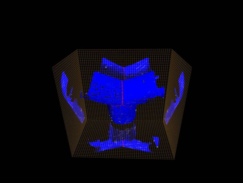
home region, the manipulator switches into rotation mode, centroid co and po is larger than the distance between pt and
then the Eule angles captured by the gesture sensor are to ct .
be transformed into rotation matrix lm Rhand , then this On the basis of the 3D gradient operators [16], we define
rotation matrix will be left multiplied by a rotation matrix the 3D gradient decompositions for a point po as:
from the gesture sensor to the robot base coordinate system
di,o
base
Rlm . With the resulting rotation matrix base Rhand , the Ik ⇡ max (Ii Io ) · , k = x, y, z (3)
i2N k
inverse Rodrigues formula is used to transform it into the
corresponding rotation part rt+1
camera to update pcamera .
base t+1 where x, y, and z are the coordinate differences in three
During the process, the left hand’s gesture is used to store the axes, and di,o represents the distance between a current point
point cloud data Pi and the corresponding camera pose with po and its i-th neighboring point qi . Fig. 3 shows an example
respect to the base when a certain “ok” gesture is detected. of the point’s gradient along Y axis.
A 3D offset function F (x, y, z) for point clouds analogous
with the edge response function [17] for 2D pixels is
!! !" $# presented and approximated by a Taylor series expansion.
Edge !! For a given point po , the offset function F (xo , yo , zo ) can
# be expressed as a multiplication of a small offset ( x, y, z)
"! !" and a symmetric matrix H, in which Ix , Iy , and Iz can be
#
# %! %" "" calculated by:
! " Perspective X
⨀ 2
! " F (xo , yo , zo ) = [Ixo + x,yo + y,zo + z Ix,y,z ]
x, y, z
Fig. 3. Conceptual representation of the edge intensity and gradient along X x · Ix + y · Iy + z · Iz 2
the Y-axis for current point po , in which co represents the local geometric =
centroid for po and edge intensity Io with respect to po is higher than It +O x2 , y 2 , z 2
with respect to its neighbor pt . Gradient Ioy is defined as the difference x, y, z
between Io and It divided by the coordinate difference along the Y-axis. ⇡ ( x, y, z)H( x, y, z)>
(4)
2 3
Ix2 Ix Iy Ix Iz
C. Welding Seam Extraction
H = 4 Iy Ix Iy2 Iy Iz 5 (5)
To remove noise from the point cloud data without remov- Iz Ix Iz Iy Iz2
ing vital edge information, an extension of bilateral filter [15]
Inspired by approach in [17], a set of edge points
specific for 3D point cloud data is used. As the point density (e) (e) (e)
{p1 , p2 , ..., pn } is generated.
of a reconstructed workpiece model varies, few points of a
neighborhood exist within a fixed range. The establishment III. R ESULTS
of a minimum point m will provide a rational neighborhood
A. Gesture-Guide Scanning
to reduce the effect on points density. Therefore, for a given
point p 2 P, its neighboring point q can be defined as: To validate the performance of scanning the workpiece
with bare hands, the experiment uses right hand palm posi-
Nr (p) = {q 2 P | kq pk2 < r [ |N | m} (1) tion to guide the depth sensor compete the movement from
one point to another target point, and left hand gestures to
where r is the fixed radius, which can adaptively adjust execute the command of capturing point clouds. As shown
to guarantee that no less than m points will exist in the in Fig 5, we set three waypoints A, B, and C for the
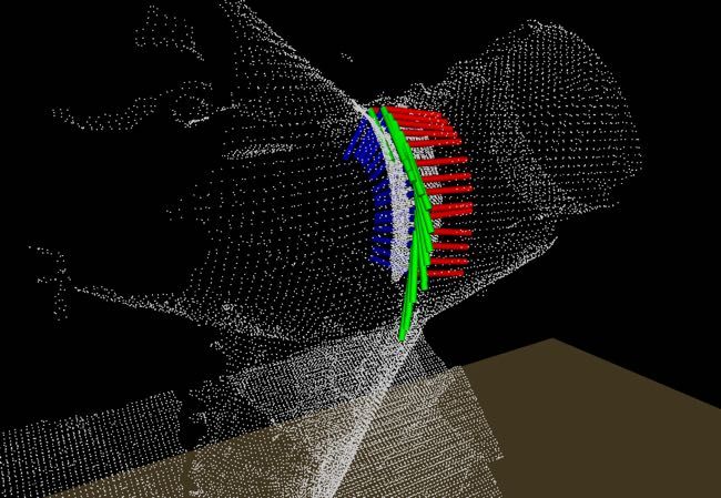
neighborhood of p. As shown in Fig. 3, the normalized dis- depth sensor to capture the point cloud from left to right.
placement between original point po and its local geometric With gestures, the depth sensor is moved from the home
centroid co can be defined as the edge intensity of po , which position to reach A, B, C. During the process, the time and
is calculated by: errors in the operation is recorded. In this experiment, 10
i=n operators who had never operated a robot were selected to
1 1X
Io = po qi (2) conduct the experiment after 10 minutes’s training. The cost
r n i=0 time of moving between different points and the distance
Pi=n between capture points and target points were obtained
where n1 i=0 qi denotes the geometric centroid for all the respectively. For capture points, it is considered successful
neighboring points corresponding to original point po . Within when the distances to the target points are within 5cm
the edge-free areas, the intensity remains low, but the value and the captured point clouds cover the whole workpiece.
will increase when approaching edges and reaches a local While for moving paths, it is considered successful when the
maximum in the intensity space at edges. Fig. 3 shows a side robot moves between different points without any collisions.
view of two intersecting point cloud surfaces as an example, The maximum average errors at three points are 4.3cm,
in which the edge intensity Io of edge point po is much the moving paths Home-A and AB both success, only once
higher compared with the intensity It of its neighbor pt in operation happens a collision when moving along BC path.
non-edge region, as the distance between the local geometric Generally, the robustness is good.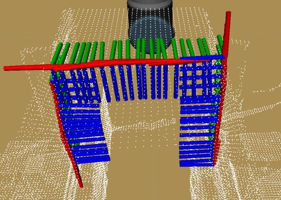
Gradient Map
Gradient Map
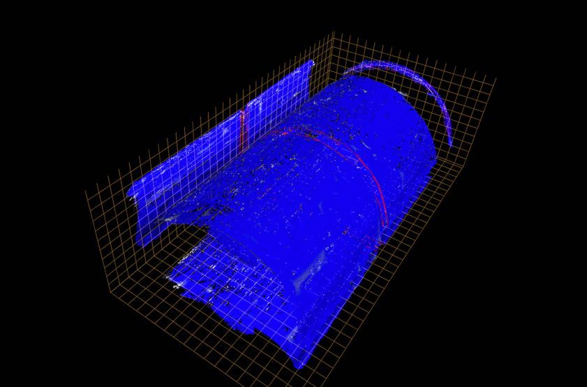
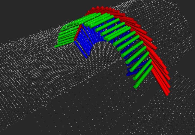
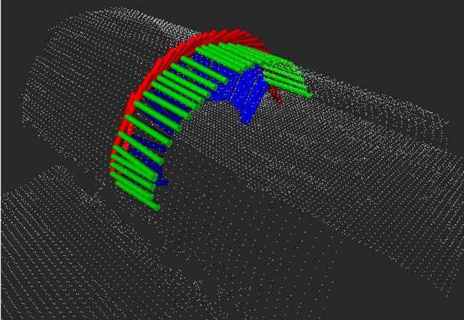
(a) (b) (c) (d) (e) (f)
Fig. 4. Results of different processes in the proposed system. (a) Two actual welding metal workpieces, cylinder and Y-shape. (b) Reconstructed models
of workpieces with a depth map. (c) Welding seam extracted with the edge intensity gradient-based algorithm. (d) Rasterized views of extracted edge
points. (e, f) 6-DOF welding path after interpolation.
(a) (b) (c) [2] J. Fan, S. Deng, et al., “An initial point alignment and seam-tracking
system for narrow weld,” IEEE Trans. Industr. Inform., vol. 16, no. 2,
pp. 877–886, 2019.
[3] C. Diao, J. Ding, S. Williams, Y. Zhao, et al., “A passive imaging
system for geometry measurement for the plasma arc welding process,”
IEEE Trans. Ind. Electron., vol. 64, no. 9, pp. 7201–7209, 2017.
[4] X. Li, X. Li, et al., “Automatic welding seam tracking and identifi-
cation,” IEEE Trans. Ind. Electron., vol. 64, no. 9, pp. 7261–7271,
2017.
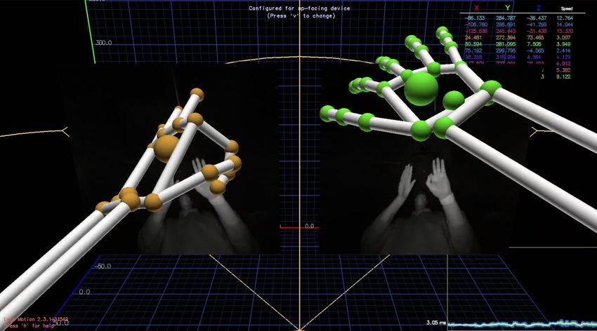
Fig. 5. (a) Real environment. (b) Three waypoints in Rviz. (c) Hand [5] H. N. M. Shah et al., “Review paper on vision based identification,
gestures in Leap Motion visualizer. detection and tracking of weld seams path in welding robot environ-
ment,” Mod. App. Sci., vol. 10, no. 2, pp. 83–89, 2016.
[6] A. Rout, B. Deepak, and B. Biswal, “Advances in weld seam tracking
techniques for robotic welding: A review,” Robot. Cim-Int. Manuf.,
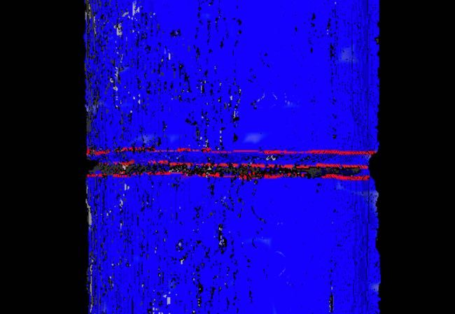
B. Welding Path Detection vol. 56, pp. 12–37, 2019.
[7] L. Nele, E. Sarno, and A. Keshari, “An image acquisition system for
After rasterization, the harmonic mean of accuracy is taken real-time seam tracking,” Int. J. Adv. Manuf. Tech., vol. 69, no. 9-12,
to measure the overall performance. The mean is defined as: pp. 2099–2110, 2013.
[8] Y. Ding, W. Huang, and R. Kovacevic, “An on-line shape-matching
3 weld seam tracking system,” Robot. Cim-Int. Manuf., vol. 42, pp. 103–
F1 = (6) 112, 2016.
axy1 + axz1 + ayz1 [9] R. Manorathna, P. Phairatt, et al., “Feature extraction and tracking of
a weld joint for adaptive robotic welding,” in Int. Conf. Cont. Auto.
where axy1 , axz1 and ayz1 denote the accuracy calculated for Robot & Vis., 2014, pp. 1368–1372.
the xy, xz, and yz planes after rasterization. Each detected [10] L. Zhang, Y. Xu, S. Du, W. Zhao, Z. Hou, and S. Chen, “Point cloud
based three-dimensional reconstruction and identification of initial
edge point is displayed in red, and the ground truth path point welding position,” in Trans. Intel. Weld. Manuf., 2018, pp. 61–77.
is manually marked in green based on point cloud generated [11] S. M. Ahmed, Y. Z. Tan, et al., “Edge and corner detection for
by a high-precision 3D scanner. The overall performance unorganized 3d point clouds with application to robotic welding,”
in IEEE/RSJ Int. Conf. on Robots and Intelligent Systems, 2018, pp.
calculated on the basis of the coverage of the red edge point 7350–7355.
over the ground truth path rasterized on different planes. The [12] V. Patil, I. Patil, et al., “Extraction of weld seam in 3d point clouds
results of two workpieces during the entire process in the for real time welding using 5 dof robotic arm,” in Int. Conf. Cont.,
Auto. and Robot, 2019, pp. 727–733.
proposed system is shown in Fig. 4. For more detailed results, [13] L. Jing, J. Fengshui, and L. En, “Rgb-d sensor-based auto path
please refer to [18]. generation method for arc welding robot,” in Chinese Control and
Decision Conf., 2016, pp. 4390–4395.
IV. C ONCLUSION [14] K. Zhang, M. Yan, T. Huang, J. Zheng, and Z. Li, “3d reconstruction of
complex spatial weld seam for autonomous welding by laser structured
This article presents a sensor-guided welding robotic light scanning,” J. Manuf. Process, vol. 39, pp. 200–207, 2019.
[15] J. Digne and C. De Franchis, “The bilateral filter for point clouds,”
system [19]. Specifically, an interactive algorithm based Image Processing On Line, vol. 7, pp. 278–287, 2017.
on gesture is first proposed to scan the workpiece in an [16] Y. Zhang, “Quantitative study of 3d gradient operators,” Image and
intuitive manner. Then, the system reconstructs a 3D point vision computing, vol. 11, no. 10, pp. 611–622, 1993.
[17] C. G. Harris et al., “A combined corner and edge detector.” in Alvey
cloud model of the target by a linear ICP algorithm. Next, vision conference, vol. 15, no. 50, 1988, pp. 10–5244.
after filtering, the welding seam joints is robustly identified [18] P. Zhou, R. Peng, M. Xu, V. Wu, and D. Navarro-Alarcon, “Path
using a gradient-based edge detection approach. Based on planning with automatic seam extraction over point cloud models for
robotic arc welding,” IEEE Robotics and Automation Letters, vol. 6,
the detected seam, a smooth 6-DOF path is computed for no. 3, pp. 5002–5009, 2021.
execution. [19] A. Cherubini and D. Navarro-Alarcon, “Sensor-based control for
human-robot collaboration: Fundamentals, challenges and opportuni-
R EFERENCES ties,” Front Neurorobotics, vol. 14, p. 113, 2021.
[1] Y. Xu, H. Yu, et al., “Real-time seam tracking control technology
during welding robot gtaw process based on passive vision sensor,” J
Mate Process Tech., vol. 212, no. 8, pp. 1654–1662, 2012.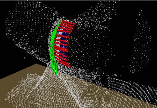
You can also read