Device Localization using mmWave Ranging with Sub-6-assisted Angle of Arrival Estimation
←
→
Page content transcription
If your browser does not render page correctly, please read the page content below

“© 2018 IEEE. Personal use of this material is permitted. Permission from IEEE must be obtained for all other uses, in any
current or future media, including reprinting/republishing this material for advertising or promotional purposes, creating
new collective works, for resale or redistribution to servers or lists, or reuse of any copyrighted component of this work in
other works.”

          Device Localization using mmWave Ranging with
             Sub-6-assisted Angle of Arrival Estimation
                                Nebojsa Maletic† , Vladica Sark† , Jesús Gutiérrez† and Eckhard Grass†‡
                                        † IHP,
                                             Im Technologiepark 25, 15236, Frankfurt (Oder), Germany
                                                  ‡ Humboldt-Universität zu Berlin, Germany

                                         Email: {maletic, sark, teran, grass}@ihp-microelectronics.com

           Abstract—Millimeter wave (mmWave) communication is a             this feature can be useful for new services such as safety
        promising solution for achieving high data rates and low latency    critical applications, augmented reality [9], assisted living
        in future wireless networks. 5G systems are expected to fulfill     [10]. In addition, position information can used for beam
        these strict requirements using, among others, mmWaves. The
        nature of the communication in these bands considering human        training overhead reduction as well as handovers between
        mobility make the challenges even complex for reasons like high     access points.
        beam training overhead. Features like ranging and localization         Localization using mmWave signals is gaining more atten-
        are becoming key to overcome these limitations. In this paper, we   tion nowadays. In [11], [12], classical localization methods
        address the problem of device localization in the mmWave band.      using different signal features like Received Signal Strength
        We propose a solution that leverages the co-existence of Sub-
        6 GHz and mmWave connectivity at access and mobile nodes.           (RSS), Time of Arrival (ToA) and Time Difference of Arrival
        Our solution relies on Angle of Arrival estimation using Sub-6      (TDoA) are investigated. A method for mmWave localization
        signal at the access node. This information is provided to the      and tracking using RSS and signal phase called ”mTrack”
        mmWave part for subsequent beam training phase and high-            is proposed in [13]. In [14] a method for mmWave device
        resolution ranging. To validate the proposed solution, a number     localization in indoor environment is proposed. This method
        of measurements are performed showing its feasibility.
                                                                            does not require any knowledge about the surrounding envi-
                              I. I NTRODUCTION                              ronment or the location and the number of access points. In
                                                                            [15] simultaneous localization and mapping (SLAM) has been
           To meet high demands for high data-rates access, capacity
                                                                            investigated using mmWave signals. Different methods for
        of current wireless networks has to increase. There is an aim
                                                                            localization using single anchor node exploiting multi-reflected
        of 1000× increase in data traffic predicted by 5G till 2020 [1],
                                                                            paths are given in [16]. In [17] joint localization and position
        which might not be achieved with current 4G networks. That
                                                                            orientation for mmWave is investigated. Impact of beamform-
        is why new spectrum bands in the millimeter wave (mmWave)
                                                                            ing strategies on mmWave localization is analyzed in [18].
        spectrum (i.e. 30 – 300 GHz) are seen promising due to
        large amount of unutilized bandwidth available worldwide            Nevertheless, according to [9], [19] multi-connectivity i.e. a
                                                                            legacy network link and an mmWave link, shall be supported
        [2], [3], [4]. MmWave communication can provide gigabit-
                                                                            in future wireless networks. This means both access nodes
        per-second (Gbps) data rates and low latency. Solutions are
                                                                            and mobile nodes will have Sub-6 and mmWave interfaces. In
        already available on the market for the 60 GHz band, like those
                                                                            such scenario, information from a lower frequency band can
        for local and personal networks following IEEE 802.11ad [5]
                                                                            be used to support the communication in the mmWave band.
        and IEEE 802.15.3c [6] standards, respectively. Currently, both
                                                                            In [20] the authors have investigated the use of channel state
        academia and industry are investigating 60 GHz solutions for
                                                                            information acquired at the lower frequency band (Sub-6 GHz)
        cellular fronthaul and backhaul networks [7]. However, the
        high data rates come at the cost that this communication needs      to estimate the mmWave channel. Out-of-band measurements
                                                                            acquired in the Sub-6 band are used to reduce the beam
        to be highly directional. This is associated with the inherent
                                                                            training overhead for mmWave communication in [21] and
        path loss at mmWave frequencies [4]. Nevertheless, small
                                                                            [22].
        wavelength (5 mm at 60 GHz) allows deployment of large
                                                                               Owing to the aforementioned, in this paper we envision a
        antenna arrays which can be packed in small form factor. This
                                                                            solution for mmWave localization exploiting multiconnectivity
        way, mmWave systems can achieve sufficient beamforming
                                                                            - Sub-6 and mmWave - at access and mobile nodes. We use
        gain to combat the inherent high free-space path loss and to
                                                                            the Sub-6 band as a side channel to determine Angle of Arrival
        provide sufficient link budget [3], [4]. In addition to Gbps
        data communication, there are other features like localization      (AoA) at the side of access node. This information is provided
                                                                            to the mmWave part to speed up the beam training process,
        and ranging that can be beneficial to mmWave systems. For
                                                                            after which mmWave ranging is performed to obtained cen-
        example, combined data communication and high-resolution
                                                                            timeter precision distance estimates. Using the estimated AoA
        ranging has been demonstrated in [8]. Regarding localization,
                                                                            and the distance estimate, a fairly accurate position of mobile
                                                                            node can be obtained. To prove this, AoA estimation, beam
       978-1-5386-4729-5/18/$31.00
                                   c 2018 IEEE                              training and ranging measurements are performed showing the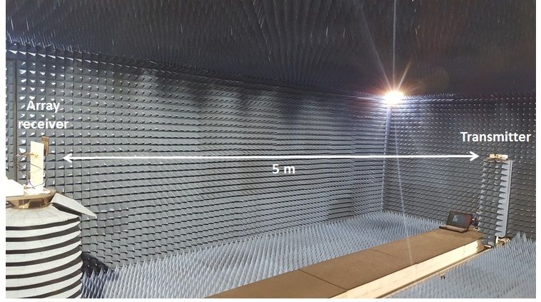
mmWave
          antenna array
                                                                                       Antenna geometry            mmWave device
             Sub-6
         antenna array

                                                                                                        Beam                                   mmWave
                                                                                     Codebook
                                                                                                       selector
                                                                                                                       LoS or NLoS?
                                                                                                                                             antenna array
                                                                                                     AoA
                                                        mmWave link
                                           Sub-6 link                                Synch.

                                                                                                                  Sub-6 GHz device
                                                                                                     AoA

         BS                                                           MS                                AoA
                                                                                                                           Detection
                                                                                                                                               Sub-6
                                                                                                                                           antenna array
                                                                                                     estimation

                                                                                              Array calibration        Antenna geometry

                          Fig. 1. System architecture example.
                                                                                               Fig. 2. BS multi-band node architecture.

feasibility of the proposed solution.
  The remainder of this paper is organized as follows: in                                     III. S IGNAL PROCESSING ENGINE
Section II we introduce the concept and system architecture.                  Once the general procedure has been described, we present
Key signal processing blocks are described in Section III.                 key signal processing steps to obtain position estimate: AoA
Implementation and evaluation of the proposed solution is                  estimation, beam training and ranging.
presented in Section IV, while concluding remarks and future
work is given in Section V.                                                A. Angle of arrival estimation
                                                                              The BS is equipped with an antenna array of P omni-
        II. S YSTEM CONCEPT AND ARCHITECTURE                               antennas in the Sub-6 band and is able to estimate the angle
   We consider a system with two endpoints both having Sub-6               of arrival (AoA) of the incoming signal from the MS. For this,
and mmWave radios. At each endpoint the two radio interfaces               different methods can be used, from which the most known
are synchronized. In our scenario one endpoint is stationary               methods are MUSIC [23], root-MUSIC [24] and ESPRIT [25].
- referred as base station (BS) - and the other endpoint is                In this work, our focus is on MUSIC-based methods.
mobile - referred as mobile station (MS). The MS has a single                 The theory behind AoA estimation using MUSIC-based
Sub-6 antenna and mmWave antenna array, while the BS is                    methods is as follows. An ULA consists of P isotropic
equipped with antenna arrays in both frequency bands. Both                 antennas separated from each other with a distance of d ≤ λ/2,
endpoints have a single radio-frequency (RF) chain at 60 GHz               where λ is the wavelength of the plane wave received by the
and beamforming is performed in RF domain using a network                  array. We consider L narrowband plane waves impinging on
of phase shifters. The system architecture is shown in Fig. 1.             the ULA from directions θ1 , θ2 , ..., θL from the main response
   The BS architecture is shown in Fig. 2. It consists of an               axis. We assume π/2 ≤ θ1 ≤ θ2 ≤ ... ≤ θL ≤ −π/2. At the
mmWave device on top and a Sub-6 at the bottom. The                        time instant k, the received signal vector x(k) ∈ CP ×1 can
mmWave part comprises a uniform linear array (ULA) of                      be expressed as
Na antennas and a beamforming unit with beam steering
capabilities with a certain angular range. Its Sub-6 counterpart                           x(k) =      a(θi )si (k) + n(k),             (1)
                                                                                                                   i
has an antenna array of P omni-directional antennas and it is
able to detect signal direction of any paired MS. The MS has               where si (k) is the complex envelope of the i-th signal, n(k) ∈
an mmWave device with an ULA of Ma antennas and a Sub-                     CP ×1 is the noise vector at the time instant k, and a(θi )) is
6 device with a single antenna element. The MS transmits                   the array response vector defined as [26]
periodically beacon frames in the Sub-6 band to the BS. The                                 1  j 2π d sin(θ)                2π
                                                                                                                                        T
BS acquires this signal with the antenna array and processes                      a(θ) = √      e λ           , ..., ej(P −1) λ d sin(θ) . (2)
                                                                                             P
it to obtain an estimation of the AoA. The BS replies to
the MS with a reply frame in the same band signaling the                   The expression in (1) can be written in matrix form as
upcoming beam training phase. In addition this signal can                                                 x(k) = As(k) + n(k),                               (3)
carry additional information, e.g. beam training request from
                                                                                                                                          P ×L
the BS side. The BS uses the estimated AoA using the Sub-6                 where A = [a(θ1 ), a(θ2 ), ..., a(θL )] ∈ C      and s(k) =
                                                                                                        T
transmission to steer the beam toward the MS in the mmWave                 [s1 (k), s2 (k), ..., sL (k)] ∈ CL×1 . MUSIC-based algorithms
band accordingly. The MS trains its beams and chooses the                  estimate AoA based on the covariance matrix of the the
one with the highest signal-to-noise ratio (SNR). Once the                 received signal, which is given by
beams are aligned, BS and MS perform distance estimation
                                                                                        R = E x(k)x(k)H = ASAH + σ 2 IP ,             (4)
using Two-way ranging (TWR). Finally, having both AoA and
distance estimation between BS and MS, the BS can determine                where
                                                                                S is the
                                                                                        transmitted data covariance matrix given as
the position of the MS with respect to its position.                       E s(k)s(k)H and IP is the identity matrix of size P × P .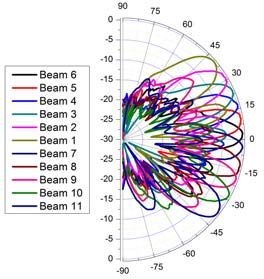
AoAsub-6     AoA                                                        BS       beacon frame
                                                                                                                                   MS
                  8        1          AoD             8    1                            Sub-6 device
                                                                                                                 ack frame
                                                                                                                                    Sub-6 device
                                                                                                                                     Tb
              7                2                  7            2                        mmWave device
                                                                                                               MS train frame 1     mmWave device
              6                3                  6            3                                       Ts
                                                                                                                                    Ts
                  5        4                          5    4                                                   MS train frame 2

                      BS                                  MS
                                                                                                                MS train frame M
Fig. 3. mmWave beams (sectors) at BS and MS. Estimated Sub-6 AoA in
sector 2, BS angle of departure (AoD) in sector 2 too, and MS AoA in sector
7.                                                                                       (M+S+1)Ts
                                                                                                                 reply frame

Taking K snapshots of the received signal, a sample covari-                                                    BS train frame 1
ance matrix R ∈ CP ×P can be calculated as
                                   1
                                     K
                                                                                                               BS train frame S
                           R=          x(k)x(k)H .                     (5)                                      ranging phase
                                   N
                                     k=1

From the eigenvalues of R, both signal and noise powers can                                       Fig. 4. System architecture example.
be obtained. There exist P eigenvalues, arranged in ascending
order, from which the first M L eigenvalues correspond to
                                                                              refinement phase at the BS starts. The BS trains its beam in
noise subspace and the remaining L eigenvalues corresponds
                                                                              successive STs time slots (S < N ), while the MS sends to
to signal subspace. Eigenvectors associated with the first
                                                                              the BS the training frame using the previously trained beam.
M L eigenvalues form the noise subspace Un ∈ CP ×P −L .
                                                                              After STs time slots, the beam training phase ends. In the
For the MUSIC method, pseudo-spectrum is calculated as
                                                                              best case, when there is no beam refinement request from the
P (θ) = 1/a(θ)H Un UH    n a(θ). For the root-MUSIC method,
                                                                              BS, beam training procedure lasts for M + 1 time slots. With
the roots of the equation a(z −1 )H Un UH
                                        n a(z) = 0 are used to
                                                                              the BS beam refinement, it lasts for M + S + 1 time slots.
obtain the estimates of DoAs, where a(z) is the array response
                                              2π                              The beam training procedure is shown in Fig. 4. Assuming
vector with the argument z given by z = ej λ d sin(θ) .
                                                                              N = M = 16, in the best case scenario Sub-6 GHz assisted
B. Sub-6 GHz assisted beam training                                           beam training lasts for 17 time slots compared to exhaustive
                                                                              beam search which needs N · M + 1 = 257 time slots. This
   We assume each endpoint (BS or MS) has a codebook                          way beam training latency can be reduced up to 93.4 %.
consisting of N (M ) beams or sectors, N ≥ Na (M ≥ Ma ),
to cover the angular space of interest. The estimated Sub-6                   C. Ranging phase
AoA is used to narrow down the angular search space. As                          A few different methods exist for distance and position
a result, the number of BS mmWave beams used for beam                         estimation of a wireless node, based on the time-of-flight
training can be significantly reduced. The BS starts the beam                 (ToF) estimation. The simplest one is based on ToA with
training phase using the beam closest to the estimated AoA. In                the working principle shown in Fig. 5a. Both nodes must be
addition, it can request a beam training from the MS in order                 synchronized before the ToA method is performed. Node N1
to refine its beam. This information can be provided within a                 transmits a waveform which is received by node N2 . Node
acknowledge frame sent to the MS after AoA estimation. An                     N2 knows the exact time of transmission of the waveform and
example of BS and MS mmWave beams (sectors) and Sub-6                         estimates the ToA of the received waveform. Having both time
AoA is shown in Fig. 3.                                                       of transmission and the ToA, the ToF can be easily estimated.
   We assume that two nodes are synchronized during Sub-                      This method requires precise synchronization, which cannot
6 communication. Once the Sub-6 AoA is available, the BS                      be easily achieved. Two way ranging (TWR) is a ranging
triggers the mmWave communication by sending a training                       method which has significantly reduced synchronization re-
frame to the MS towards the direction of the estimated AoA                    quirements compared to ToA-based ranging. A basic TWR
(see Fig. 3 - left). The training frame is sent M times in M                  scheme is shown in Fig. 5b. The TWR starts from node N1 ,
successive time slots of duration Ts . At the same time, the                  by transmitting a waveform to node N2 . Node N2 receives
MS is listening using different beams in each time slot to find               this waveform and replies back to N1 with a similar waveform.
its AoA. Based on the received SNR or other representative                    Node N1 measures the round trip time and node N2 has a fixed
metric, the MS finds its best beam (Fig. 3 - right). If there is no           reply time (or estimates it). The ToF can be easily estimated
beam training request from the BS side, the MS sends a reply                  from the round trip time and the reply time.
frame to finalize the beam training session. If the reply frame
is received at the BS, the beam training phase is finalized and                         IV. I MPLEMENTATION AND EVALUATION
the ranging phase can start. However, if the BS has requested                   This section presents the results of the evaluation of the sys-
beam refinement, after a reply frame is received, the beam                    tem introduced in previous sections. For Sub-6 AoA estimation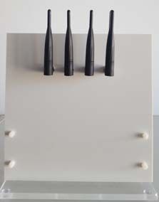
0 0
Pseudo-spectrum (dB)
Pseudo-spectrum (dB)
-10
-5
-20
-10
spectum MUSIC: MS @ -35 deg -30 spectum MUSIC: MS @ 0 deg
root-MUSIC: MS @ -35 deg root-MUSIC: MS @ 0 deg
-15 -40
(a) ToA-based ranging (b) Two-way ranging (TWR) -50 0 50 -50 0 50
Angle (degrees) Angle (degrees)
Fig. 5. ToF ranging methods.
0 0
Pseudo-spectrum (dB)
Pseudo-spectrum (dB)
-5
-10
-10
-20
-15
spectum MUSIC: MS @ 30 deg -30 spectum MUSIC: MS @ 50 deg
-20 root-MUSIC: MS @ 30 deg root-MUSIC: MS @ 50 deg
-25 -40
-50 0 50 -50 0 50
Angle (degrees) Angle (degrees)
(a) (b) (c)
Fig. 7. AoA estimation of the pilot tone impinging the antenna array at the
angles -35, 0, 30 and 50 degrees.
Fig. 6. Analog front-ends (AFEs): a) Sub-6 GHz dipole antenna array, b) 60
GHz antenna array, and c) beams associated with the 60 GHz antenna array.
TABLE I
A NECHOIC CHAMBER : TRUE AND ESTIMATED AOA
experiments, software defined radio (SDR) devices USRPs
AoA (◦ ) -35 0 30 50
X300/X310 from Ettus are used. The SDR MS is equipped
with UBX160 daughterboard and has single dipole antenna,
AoA (◦ ) -36.4 0.02 31.1 50.6
whilst the SDR acting as the BS has TwinRXs daughterboards
connected to 4-dipole antenna array, as shown in Fig. 6
a). Omnidirectional dual band antennas (2.45 and 5.8 GHz) Next, the mmWave beam alignment experiment is per-
having 2.5 and 4.6 dBi gain, respectively, are used. For beam formed. The transmitter (BS) and the receiver (MS) are
alignment and ranging tests, 60 GHz analog frontends (AFEs) positioned face to face at the distance of five meters. The
with beamforming capability are used. The mmWave AFE signal frame used for this test consists of an IEEE 802.11ad
consists of an up/down converter, a beamformer and a phased single carrier preamble, a channel estimation field and a small
antenna array. The beamformer is an 8-channel bidirectional data field. The signal is passed through an squared root-raised
60 GHz IC fabricated in IHPs SiGe:C 130nm BiCMOS cosine (SRRC) filter with a roll-off factor of 0.25 spanned over
technology [27]. The phased antenna array is an 8-element 8 samples with oversampling factor 4 and sampled with the
linear array with maximum gain of around 11 dBi at 61.5 GHz sampling frequency of 4 GSps. For each RX beam the frame
[28]. The antenna array AFE module with the beamformer was sent 10 times from TX using fixed beam and SNR is
and the associated beams in the range -45◦ – 45◦ are shown estimated. The estimated SNR values for beams 2, 4, 5, 6, 7, 8,
in Figs. 6 b) and c). To generate the baseband signal at the and 10 are given in Table II. Using the maximal measured SNR
BS side, an arbitrary waveform generator (AWG) is used. At policy, Rx finds the best beam for subsequent communication
the MS side, the baseband signal from the AFE is sampled and ranging (in this case beam 6).
using a digital sampling oscilloscope. The acquired samples For the mmWave ranging measurement, a ToA approach
are stored in memory and processed offline. Measurements are is used as TWR cannot be implemented using the given
performed in an anechoic chamber of size 7 m (L) × 4 m (W) setup. Nevertheless, it can be assumed the variance of the
× 2.5 m (H) and an office environment. distance estimate using TWR approach results in twice the
A. Anechoic chamber measurement variance using ToA. This is true if the estimates follow normal
distribution. If it is not the case, it can be used as a first
The measurement setup is shown in Fig. 8a. The distance
approximation for the distance estimation error. The waveform
between the transmitter (MS) and the receiver (BS) is five
used for the ranging test is a m-sequence of length 1023. The
meters. The system is calibrated according to [29]. The pilot
sequence is BPSK modulated and filtered using an SRRC pulse
tone is sent at the center frequency of 2.45 GHz with the
shaping filter with a roll-off factor of 1. The 3 dB bandwidth is
sampling rate of 1 MSps. The test is performed for different
angles. At the BS side, the signal is recorded and processed
with MUSIC and root-MUSIC methods as described in Section TABLE II
III. Results are plotted in Fig. 7, whereas the estimated angles B EAM DEPENDENT SNR ESTIMATION
are given in Table I. Values that are obtained based on 1000
measurements shows that the estimated AoAs are within 2 Beam index 2 4 5 6 7 8 10
degrees from the true AoA and that the standard deviation is
SNR (dB) -2.7 9.0 7.4 15.9 14.1 5.5 -0.2
below 0.2 degrees.(a) Anechoic chamber (b) Office environment
Fig. 8. Measurement environments.
5.5 0.03
BS
ide a l
e s tima te d dis ta nce s MS
RMS E 0.025
4.5 y Pilars
x
Cabinets
Me a s ure d dis ta nce [m]
0.02
3.5
Wooden doors
RMS E [m]
P3 Glass walls
0.015
2.5
P4 P2 Entrance
0.01
P1
1.5
P5
0.005
0.5
0 0
0 0.5 1 1.5 2 2.5 3 3.5 4 4.5 5 5.5
True dis ta nce [m]
Fig. 9. Estimated distance vs true distance and root mean squared error.
Fig. 10. The office floor plan.
1 GHz. The distance between the transmitter and the receiver TABLE III
is varied from 1 to 5 meters with a step of 0.4 meters. For O FFICE : AOA ESTIMATION AND RANGING ACCURACY
each distance a few hundred ranging waveforms are received at
the receiver and acquired using the oscilloscope. The acquired AoA (◦ ) R (m) Abs. error
Location
samples are processed offline. The estimated distance as a
True Est. True Est. AoA (◦ ) R (cm)
function of the true distance is shown in Fig. 9. It can be
noticed that the estimated distance accurately matches the true P1 -26 -29.7 6.66 6.5 3.7 16
distance. The root mean squared error (RMSE) is below 1 cm.
P2 -10 -15 4.45 4.47 5 2
Cumulative density function (CDF) of the distance estimates
around the mean value reveals that the achievable precision P3 -38 -43.2 4.03 4.04 5.2 1
falls below 2 centimeters for each of the distance measures.
P4 44 44.3 6.00 6.1 0.3 10
B. Measurement in an office environment P5 30 25 8.98 9.02 5 4
In addition to the antenna chamber, the same measurements
were performed in an office environment shown in Fig. 8b.
The BS is placed on a wooden cabinet at the height of 175 Minimal RMSE is 2.5 cm and maximal is 17 cm. Regarding
cm, while the MS was positioned at five different locations the AoA maximal absolute error is around 5 degrees. The
at the height of 100 cm such that Line-of-Sight (LoS) path reason for the higher errors compared to the antenna chamber
with the BS exists. The office floor plan with the measurement might be due to harsh propagation environment such as the
locations is illustrated in Fig. 10. In this case the measurements office environment. In addition, more precise calibration of the
were performed at the frequency of 5.8 GHz in order to antenna array across angles and versus temperature is needed
avoid interference from the WiFi APs used for Internet access (i.e. periodic calibration is needed).
operating in the 2.4 GHz frequency band.
For each measuring location (P1-P5), the mean estimated V. C ONCLUSION
AoA and the mean range estimate R are reported in Table In this paper, we have proposed a solution for a device
III. The estimated distance is very close to the true distance. localization in the mmWave band. Our solution leverages fromangular information extracted from Sub-6 communication, [11] F. Lemic et al., ”Localization as a feature of mmWave communication”,
which is necessary to simplify the beam training process International Wireless Communications and Mobile Computing Confer-
ence (IWCMC), Paphos, pp. 10331038, 2016
at mmWave frequencies and favors the mmWave ranging [12] H. El-Sayed, G. Athanasiou and C. Fischione, ”Evaluation of lo-
procedure. Based on the acquired angle, beam training and calization methods in millimeter-wave wireless systems”, IEEE 19th
the ranging between a base station and a mobile station International Workshop on Computer Aided Modeling and Design of
Communication Links and Networks (CAMAD), Athens, pp. 345349,
is performed. For the key parts of the described system, 2014
measurements were conducted in an anechoic chamber and [13] T. Wei et al., ”mTrack: high-precision passive tracking using millimeter
an office environment. The results obtained in the anechoic wave radios,” in Mobile Computing and Networking, ACM, pp. 117-129,
2015
chamber have shown the feasibility of the proposed method [14] J. Palacios, P. Casari and J. Widmer, ”JADE: Zero-knowledge device
by successfully obtaining the AoA with the error less than localization and environment mapping for millimeter wave systems,”
two degrees and a centimeter precision distance estimate. In an IEEE INFOCOM 2017 - IEEE Conference on Computer Communica-
tions, Atlanta, GA, 2017, pp. 1-9.
office environment, the realistic nature of the environment, e.g. [15] F. Guidi, A. Guerra and D. Dardari, ”Millimeter-wave massive arrays for
the existence of reflections, make the obtained results slightly indoor SLAM,” 2014 IEEE International Conference on Communications
worse than those from the anechoic chamber. Maximal angular Workshops (ICC), Sydney, pp. 114120, 2014
[16] A. Olivier et al., ”Lightweight indoor localization for 60-GHz millimeter
and distance errors were five degrees and 16 cm. Nevertheless, wave systems”, IEEE International Conference on Sensing, Communica-
the proposed solution can estimate fairly accurate position tion and Networking (SECON 2016), pp. 2730, London, 2016
of an mobile node which can be made more accurate with [17] A. Shahmansoori et al., ”5G position and orientation estimation through
millimeter wave MIMO”, IEEE Globecom Workshops, 2015
additional calibration of the system. [18] A. Guerra, F. Guidi and D.Dardari, ”On the impact of beamforming strat-
Future work will include developing a more automated egy on mm-Wave localization performance limits”, IEEE ICC Workshop
solution using SDR platforms supporting both Sub-6 and on Advances in Network Localization and Navigation (ANLN), Paris,
pp.809814, 2017
mmWave two-way ranging, and testing its functionality in [19] -, Deliverable 4.1, ”Preliminary radio interface concepts for mm-wave
diverse environments (indoors and outdoors) and under MS mobile communications”, mmMagic project
mobility. [20] A. Ali, N. Gonzlez-Prelcic and R. W. Heath, ”Estimating millimeter
wave channels using out-of-band measurements,” 2016 Information The-
ory and Applications Workshop (ITA), La Jolla, CA, 2016, pp. 1-6.
ACKNOWLEDGMENT [21] T. Nitsche, A. B. Flores, E. W. Knightly and J. Widmer, ”Steering with
eyes closed: Mm-Wave beam steering without in-band measurement,”
This work has received funding from the European Unions 2015 IEEE Conference on Computer Communications (INFOCOM),
Horizon 2020 research and innovation programme under grant Kowloon, pp. 24162424, 2015
[22] A. Patra, L. Simi and M. Petrova, ”Design and experimental evaluation
agreement No. 671551 (5G-XHaul project). The European of a 2.4 GHz-AoA-enhanced beamsteering algorithm for IEEE 802.11ad
Union and its agencies are not liable or otherwise responsible mm-wave WLANs,” 2017 IEEE 18th International Symposium on A
for the contents of this document; its content reflects the view World of Wireless, Mobile and Multimedia Networks (WoWMoM),
Macau, 2017, pp. 1-10.
of its authors only. [23] R. O. Schmidt, ”Multiple Emitter Location and Signal Parameter Esti-
mation”, IEEE Transactions on Antennas and Propagation, Vol. AP-34,
R EFERENCES No. 3, pp. 276-280, 1986
[24] A. J. Barabell, ”Improving the resolution performance of eigenstructure
[1] J. G. Andrews et al., ”What Will 5G Be?”, IEEE Journal on Selected based direction-finding algorithms”, in Proc. ICASSP, Boston, MA, pp.
Areas in Communications, vol. 32, no. 6, pp. 1065-1082, June 2014 336339, April 1983,
[2] W. Roh et al., ”Millimeter-wave beamforming as an enabling technology [25] R. Roy, A. Paulraj and T. Kailath, ”Estimation of Signal Parameters
for 5G cellular communications: theoretical feasibility and prototype via Rotational Invariance Techniques - ESPRIT”, Military Communi-
results,” IEEE Commun. Mag., vol. 52, no. 2, pp. 106-113, 2014 cations Conference - Communications-Computers: Teamed for the 90s
[3] T. S. Rappaport et al., ”Millimeter wave mobile communications for 5G (MILCOM), Monterey, pp.41.6.141.6.5, 1986
cellular: It will work!”, IEEE Access, vol. 1, pp. 335-349, 2013 [26] H. L. Van Trees, Optimum Array Processing - Part IV: Detection,
[4] T. Rappaport, R. W. Heath Jr., T. Daniels, and J. Murdock, Millimeter Estimation, and Modulation Theory, Wiley, 2002
wave wireless communications, Prentice Hall, 2014 [27] A. Malignaggi, M. Ko, M. Elkhouly, and D. Kissinger, ”A scalable
[5] IEEE Standard 802.11ad, ”Wireless LAN Medium Access Control (MAC) 8-channel bidirectional V-band beamformer in 130nm SiGe:C BiCMOS
and Physical Layer (PHY) Specifications. Amendment 3: Enhancements technology,” in IEEE MTT-S Int. Microw. Symp. Dig., Honolulu, HI, Jun.
for Very High Throughput in the 60 GHz Band”, 2012 2017, pp. 1-4.
[6] T. Baykas et al., ”IEEE 802.15.3c: the first IEEE wireless standard for [28] www.ihp-microelectronics.com/de/forschung/drahtlose-systeme-und-
data rates over 1 Gb/s,” in IEEE Communications Magazine, vol. 49, no. anwendungen/abgeschlossene-projekte/prelocate.html
7, pp. 114-121, July 2011 [29] -, ”Phase synchronization capability of TwinRX boards and DoA esti-
[7] J. G. Teran et al., ”5G-XHaul: a converged optical and wireless solution mation”, Whitepaper, Available at: www://kb.ettus.com
for 5G transport networks”, Transactions on Emerging Telecommunica-
tions Technologies, Wiley-Blackwell, 2016, doi:10.1002/ett.3063
[8] M. Ehrig, M. Petri, V. Sark, J. G. Teran and E. Grass, ”Combined high-
resolution ranging and high data rate wireless communication system
in the 60 GHz band”, 11th Workshop on Positioning, Navigation and
Communication (WPNC), pp. 16, 2014
[9] M. Ehrig et al., ”Reliable wireless communication and positioning en-
abling mobile control and safety applications in industrial environments”,
IEEE International Conference on Industrial Technology (ICIT), Toronto,
pp. 13011306, 2017
[10] K. Witrisal et al., ”High-accuracy localization for assisted living: 5G
systems will turn multipath channels from foe to friend”, IEEE Signal
Processing Magazine, vol. 33, no. 2, pp. 5970, 2016You can also read