DISTRIBUTED VERTICAL LINE ARRAY (DVLA) ACOUSTIC RECEIVER
←
→
Page content transcription
If your browser does not render page correctly, please read the page content below
3rd International Conference & Exhibition on "Underwater Acoustic Measurements: Technologies & Results"

      DISTRIBUTED VERTICAL LINE ARRAY (DVLA) ACOUSTIC
                         RECEIVER

Peter F. Worcester,a Scott Carey,a Matthew A. Dzieciuch,a Lloyd L. Green,a David Horwitt,a
Jacques C. Lemire,a and Matthew Norenberga

a
 Scripps Institution of Oceanography, University of California at San Diego, La Jolla,
California 92093-0225, USA

Contact author: Peter F. Worcester, Scripps Institution of Oceanography, University of
California at San Diego, 9500 Gilman Drive, La Jolla, California 92093-0225, USA
Fax: +1-858-534-6251, Email: pworcester@ucsd.edu

Abstract: A Distributed Vertical Line Array (DVLA) receiver able to span the full water
column in water up to 6000 m deep has been developed to allow both modal and ray-based
analyses of acoustic propagation. The DVLA is made up of distributed, self-recording
hydrophones with timing and scheduling provided by a small number of central controllers,
called D-STARs. The enabling technologies for this approach are (i) the availability of flash
memory modules that can store several gigabytes of data and be located in a small pressure
case at each hydrophone, making it unnecessary to transfer data from the hydrophones to the
central controllers for storage, and (ii) inductive modems that allow low-bandwidth
communication for command, control, and time synchronization between the D-STAR
controllers and the Hydrophone Modules over standard oceanographic mooring wire. The
DVLA is modular, consisting of subarrays with a nominal length of 1000 m, each of which
has one D-STAR controller and up to 99 Hydrophone Modules. A D-STAR controller is
shackled in-line at the top of each subarray. The Hydrophone Modules are clamped to the
mooring wire at the time of deployment, making the DVLA readily configurable for different
experiments. The D-STAR clocks are synchronized acoustically, avoiding electrical
interconnections. The DVLA is navigated using acoustic transponders positioned on the
seafloor around the mooring. The Hydrophone Modules make precision temperature
measurements throughout the time that the DVLA is deployed, in order to provide the sound-
speed profiles needed for beamforming.

Keywords: Array technology, sound propagation in deep water

                                                 113
3rd International Conference & Exhibition on "Underwater Acoustic Measurements: Technologies & Results"
1. INTRODUCTION
Uncertainty due to ocean variability limits the ability to make accurate predictions of
acoustic propagation. Scattering due to internal waves and other ocean processes limits the
temporal and spatial coherence of the received signal. Recent experiments to study the basic
physics of low-frequency, long-range acoustic propagation in deep water and the effects of
environmental variability on signal stability and coherence have been constrained by the lack
of vertical line array (VLA) receivers capable of spanning the full water column in deep
water. Such arrays are required to enable the separation of acoustic modes using spatial
filtering and to fully characterize the acoustic time fronts formed in deep water propagation.
The earliest low-frequency, long-range acoustic propagation experiments, starting with the
discovery of the deep sound channel in 1944, used wideband explosive sources. These
experiments formed the basis for understanding propagation through a deterministic ocean
and have shed some light on the statistics of its variability. But it is the development over the
last two decades of low-frequency, wideband acoustic sources driven by controlled
waveforms and large vertical receiving arrays, including ones that can store a year or more of
data, that have finally provided the means to measure the spatial and temporal statistics of the
acoustic fluctuations [1]. This technology allows individual multipaths and normal modes to
be resolved and long time-series to be collected. These statistics are needed to advance the
understanding of the effects of ocean variability on acoustic propagation.
Fully autonomous VLA receivers originally developed in the early 1990s for the Acoustic
Thermometry of Ocean Climate (ATOC) project have been the workhorses in deep-water,
long-range ocean acoustic propagation experiments for over a decade [1]. These arrays,
which were developed to test and improve the understanding of acoustic propagation out to
ranges of 3–10 megameters, were first used in the ATOC Acoustic Engineering Test in 1994
[2]. The ATOC VLAs consisted of two 20-element, 700-m long subarrays, forming a 40-
element, 1400-m long array with hydrophones spaced 35 m apart [3]. It is difficult to deploy
substantially longer VLA receivers using this technology, however, because of the weight of
the complex electromechanical array cables, even though full-water-column spanning VLA
receivers are sorely needed to further the understanding of deep-water propagation.
A modular, distributed VLA receiver that is capable of spanning the full water column in
water up to 6000 m deep has therefore been developed to allow both modal and ray-based
analyses of acoustic propagation in deep water.
2. DISTRIBUTED VLA (DVLA) ARCHITECTURE
The DVLA is made up of distributed, self-recording Hydrophone Modules with timing
and scheduling provided by a small number of central controllers, called D-STARs (DVLA -
Simple Tomographic Acoustic Receivers). The enabling technologies for this approach are (i)
the availability of flash memory modules that can store several gigabytes of data and be
located in a small pressure case at each hydrophone, making it unnecessary to transfer data
from the hydrophones to the central controllers for storage, and (ii) inductively coupled
modems that allow low-bandwidth communication for command, control, and time
synchronization between the central controllers and the Hydrophone Modules over standard
oceanographic mooring wire. The DVLA is fully autonomous, recording during time periods
specified a priori. The maximum duty cycle for a one-year deployment is approximately 8%,
depending on the sample rate.
1143rd International Conference & Exhibition on "Underwater Acoustic Measurements: Technologies & Results"
The DVLA consists of subarrays with a nominal length of 1000 m, each of which has one
D-STAR controller and up to 99 Hydrophone Modules. The D-STAR is shackled in-line at
the top of each subarray. Hydrophone Modules are clamped to the mooring wire at the time
of deployment, making the DVLA readily configurable for different experiments. The D-
STARs and Hydrophone Modules are rated for operation to a depth of 6000 m. The DVLA
uses a long-baseline acoustic navigation system to measure the array position and shape as
the mooring moves in response to ocean currents.
2.1. Inductive Modem
The data link connecting the Hydrophone Modules to the D-STAR controller employs
commercially available inductive modem technology that uses standard 3x19 jacketed
oceanographic wire rope, avoiding the need for a custom electromechanical array cable [4].
Inductively coupled modems use toroidal transformers to couple data to and from instruments
clamped on the mooring cable. At each Hydrophone Module, the mooring cable passes
through a ferrite toroid, forming a single-turn primary winding for data transferred from the
D-STAR controller to the Hydrophone Module. The Hydrophone Module has a 20-turn
secondary winding to receive the data. The toroids are split in halves, so that they can be
clamped around the cable without the need to thread the mooring cable through the toroid. A
seawater return is used to complete the electrical circuit. The swaged fitting on the end of the
mooring cable distant from the D-STAR controller provides one seawater ground.
Although the D-STAR could also use a toroidal transformer to couple to the mooring
cable, it is more convenient to use a small transformer internal to the pressure case that is
connected to the end of the mooring cable through an underwater connector. In this case, the
end of the mooring cable is isolated from seawater and a clevis fitting is used to provide both
the mechanical termination and the seawater ground.
Fig. 1: Histogram of the time differences (sec) between two Hydrophone Modules with
100-turn windings on the inductive couplers.
The DVLA uses Inductive Modem Modules (IMM) and other components supplied by
Sea-Bird Electronics, Inc. [4]. Sea-Bird’s inductive modems use Differential Phase Shift Key
1153rd International Conference & Exhibition on "Underwater Acoustic Measurements: Technologies & Results"
(DPSK) modulation on a 4800-Hz carrier, providing 1200-baud, half-duplex
communications. The system is not optimized for time transfer, however. Sea-Bird therefore
modified the IMM firmware to provide precision time transfer using the IM Flag line.
Laboratory tests indicate that the modified firmware provides time transfer with a standard
deviation of 31 sec between Hydrophone Modules (Fig. 1). The absolute time delay from
the D-STAR controller to the Hydrophone Modules with a loop resistance of 100 (1000)
ohms is 9.34 (9.54) ms.
2.2. D-STAR Controller
The D-STAR controller is based on the Simple Tomographic Acoustic Receiver (STAR)
data acquisition system and acoustic source controller previously developed at Scripps
Institution of Oceanography for ocean acoustic tomography (Fig. 2). The STAR provides a
precision time base capable of keeping time autonomously with an accuracy of about 3 ms
per year. A low-power (80 mW) microcomputer compensated crystal oscillator (Q-Tech
MCXO QT-2002) serves as the primary system oscillator. A much higher power (10 W @
25C operating) rubidium oscillator (Symmetricom X72) is turned on periodically (typically
once per day) to serve as a reference to measure the frequency of the QT-2002. The
difference frequency is logged and used to correct the STAR clock after recovery.
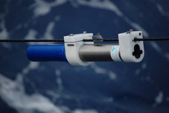
Fig. 2: D-STAR controller and a Hydrophone Module being deployed during the 2009
North Pacific Acoustic Laboratory (NPAL) Philippine Sea Pilot Study/Engineering Test
(PhilSea09). (Photograph by L. Green, Scripps Institution of Oceanography.)
The STAR also includes a long-baseline acoustic navigation system to measure mooring
motion with an absolute precision of approximately 1 m rms, using acoustic transponders
deployed on the seafloor. The D-STAR uses a single-frequency interrogate (9.0 kHz),
multiple-frequency reply (11.0, 11.5, 12.0, and 12.5 kHz) system. The D-STAR controllers
typically transmit interrogation signals once per hour continuously throughout the experiment
and record the transponder replies using a 15-s recording window.
Finally, the STARs provide a RS-232/RS-422 serial port for an external modem. In the D-
STARs, an IMM and transformer are added to the STARs, the underwater modem connector
1163rd International Conference & Exhibition on "Underwater Acoustic Measurements: Technologies & Results"
is used for the connection to the mooring cable, and the D-STAR firmware is modified to
provide control and timing signals to the Hydrophone Modules over the inductive modem
communication link.
There are no electrical connections between the D-STAR controllers. Their clocks are
therefore synchronized acoustically using the long-baseline interrogation signals. Each D-
STAR records the interrogation signals of the other D-STARs. This is equivalent to having
the D-STARs transpond off one another (although with some delay between the interrogate
and reply signals) and allows the D-STAR clocks to be compared.
2.3. Hydrophone Modules
The Hydrophone Modules are designed (i) to record low-frequency acoustic signals,
sampling at 976.5625, 1953.1250, or 3906.2500 Hz, (ii) to record the high-frequency, long-
baseline acoustic navigation signals, sampling at 39,062.5 Hz, and (iii) to make precision
temperature measurements (± 0.005°C). Separate channels of a quad, 24-bit, delta-sigma
analog-to-digital converter (Texas Instruments ADS1274) are used for each of the three
measurements. The signal conditioning and anti-aliasing filters differ from channel to
channel, as appropriate. Each Hydrophone Module writes the data to a 16 GByte Secure
Digital (SD) card. The SD cards are removed from the Modules following the experiment in
order to download the data.
The same hydrophone (High Tech, Inc. HTI-90-U), which is rated for operation from 2 Hz
to 20 kHz, is used for both the low-frequency acoustic and navigation channels. It has an
integral preamplifier. Its equivalent self-noise is below Sea State 0 (Table 1). The self-noise
levels of the signal conditioning circuitry and ADC in the low-frequency acoustic channel are
below the equivalent self-noise of the hydrophone.
Frequency Equivalent Self-Noise
(Hz) (dB re 1 µPa / √Hz)
10 54
100 35
1000 26
Table 1: Equivalent self-noise vs. frequency for the HTI-90-U hydrophone.
High-pass filters are included in both the hydrophone preamplifier (fHigh-pass = 10 Hz) and
Hydrophone Module signal conditioning circuitry (fHigh-pass = 7.7 Hz) to mitigate the effects
of low-frequency mooring strum due to vortex induced vibrations (VIV).
The Hydrophone Modules make precision temperature measurements throughout the time
that the DVLA is deployed, in order to provide the sound-speed profiles needed for
beamforming.
The Hydrophone Modules are normally completely powered off, except for the Inductive
Modem Modules, which are in a micropower state waiting for a wake-up signal from the D-
STAR controller. After broadcasting a wake-up signal, the D-STAR waits for the oscillators
(20-MHz Maxim DS4026 TCXO) in the Hydrophone Modules to warm up prior to setting the
clocks in the Modules and sending them instructions.
Each Hydrophone Module includes a USB port for programming and testing. Each
Module operates from a single 40-Amp-hour lithium battery (Electrochem, Inc. 3B6100, Size
TSD).
1173rd International Conference & Exhibition on "Underwater Acoustic Measurements: Technologies & Results"
Fig. 3: Hydrophone Module being deployed during PhilSea09. (Photograph by L. Green,
Scripps Institution of Oceanography.)
3. ACKNOWLEDGMENTS
This material is based upon work supported by the Office of Naval Research Ocean
Acoustics Program (Award Numbers N00014-03-1-0182 and N00014-08-1-0840) and
Defense University Research Instrumentation Program (DURIP) (Award Numbers N00014-
07-1-0744 and N00014-08-1-0807). Any opinions, findings, and conclusions or
recommendations expressed in this publication are those of the authors and do not necessarily
reflect the views of the Office of Naval Research.
REFERENCES
[1] P. F. Worcester and R. C. Spindel, North Pacific Acoustic Laboratory, J. Acoust. Soc.
Am., 117, pp. 1499–1510, 2005.
[2] P. F. Worcester, B. D. Cornuelle, M. A. Dzieciuch, W. H. Munk, B. M. Howe, J. A.
Mercer, R. C. Spindel, J. A. Colosi, K. Metzger, T. G. Birdsall, and A. B. Baggeroer,
A test of basin-scale acoustic thermometry using a large-aperture vertical array at 3250-
km range in the eastern North Pacific Ocean, J. Acoust. Soc. Am., 105, pp. 3185–3201,
1999.
[3] ATOC Instrumentation Group (B. M. Howe, S. G. Anderson, A. B. Baggeroer, J. A.
Colosi, K. R. Hardy, D. Horwitt, F. W. Karig, S. Leach, J. A. Mercer, K. Metzger, L.
O. Olson, D. A. Peckham, D. A. Reddaway, R. R. Ryan, R. P. Stein, K. von der
Heydt, J. D. Watson, S. L. Weslander, and P. F. Worcester), Instrumentation for the
Acoustic Thermometry of Ocean Climate (ATOC) prototype Pacific Ocean network, In
OCEANS '95 MTS/IEEE Conf. Proc., San Diego, California, pp. 1483–1500, 1995.
[4] Sea-Bird Electronics, Inc., Real-time oceanography with inductive modems,
http://www.seabird.com/pdf_documents/IMtutorialRev8.pdf, pp. 9, April 2009.
118You can also read