DMA_ADC_Transfer_1 for KIT_AURIX_TC375_LK - DMA transfer of ADC conversion results - Infineon Technologies
←
→
Page content transcription
If your browser does not render page correctly, please read the page content below
DMA_ADC_Transfer_1
for KIT_AURIX_TC375_LK
DMA transfer of ADC conversion results

AURIX™ TC3xx Microcontroller Training
V1.0.0
                Please read the Important Notice and Warnings at the end of this document
Scope of work
The DMA is used to transfer ADC measurements results to CPU0
DSPR.
At the end of an analog-to-digital conversion of the Enhanced Versatile
Analog-to-Digital Converter (EVADC) module, an interrupt is triggered, which
starts the data transfer of the converted ADC results via DMA to the CPU0
Data Scratch-Pad SRAM (DSPR0). The ADC conversion is started manually
via a command of a serial monitor.
Copyright © Infineon Technologies AG 2021. All rights reserved.Introduction
› The Direct Memory Access (DMA) transfers data from data source locations to data
destination locations without intervention of the CPU or other on-chip devices
› A DMA channel performs transactions. One transaction is made of transfers. One transfer
is made of up to 16 moves. This structure divides the data into several parts and increases
the application’s efficiency
› A DMA move is an operation that always consists of two parts:
– A DMA read move that loads DMA read move data from a source module to the DMA
– A DMA write move that stores DMA write move data from the DMA to a destination
module
› A transaction can be interrupted, however once a transfer is started, it cannot be interrupted
› A move operation (8-bit,16-bit, 32-bit, 64-bit, 128-bit or 256-bit):
1. Loads data from the data source into the DMA controller
2. Puts data from the DMA controller to a data destination
› Any DMA move engine can service a DMA request from any of the 128 DMA channels.
Channel 127 has the highest priority
› Example:
– 1024 words (32-bit per word) transaction can be composed of 256 transfers of 4 DMA
word moves, or 128 transfers of 8 DMA word moves
Copyright © Infineon Technologies AG 2021. All rights reserved.Introduction
› The Enhanced Versatile Analog-to-Digital Converter module (EVADC) of
the AURIX™ TC37x comprises 8 independent analog to digital converters
(EVADC groups) with up to 16 analog input channels each. Each,
converting with a resolution up to 12-bit
› Several request sources can request an Analog/Digital conversion
following different configurations. A conversion can be requested to be
done once or repeatedly
› Interrupts can be generated once conversions are finished
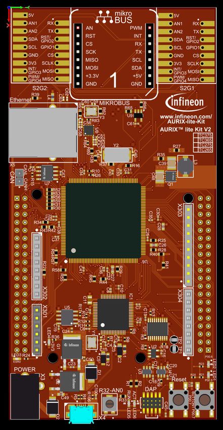
Copyright © Infineon Technologies AG 2021. All rights reserved.Hardware setup
This code example has been developed
for the board KIT_A2G_TC375_LITE.
In this example, the pin AN0, connected
to the board’s potentiometer, is used.
Note: The channels can be HW filtered by the
board, depending on which capacitor/resistors
couples are soldered. Consult the AURIX™
TC375 lite Kit’s User Manual to check which
channels are filtered by HW.
Note: The reference voltage (VAREF) of the
EVADC on the board KIT_A2G_TC375_LITE
is 3.3 V.
Copyright © Infineon Technologies AG 2021. All rights reserved.Implementation
Application use case
The DMA_ADC_Transfer_1 example works as follows:
1. The user sends a ‘1’ character via a serial monitor
2. This triggers an Analog/Digital conversion
3. Once the conversion is done and the result written in the EVADC result register, an interrupt is
triggered
4. This interrupt calls a DMA transaction, since the DMA is configured as the Interrupt Service
Provider for this ADC interrupt
5. Once the transaction is finished, an interrupt is triggered by the DMA and handled by the CPU, to
send a feedback message to the user on the serial monitor
This sequence can be repeated at any time.
Copyright © Infineon Technologies AG 2021. All rights reserved.Implementation
Configuration of the ADC
For this example, the configuration of one group using one single channel is sufficient.
In init_EVADC(), the Analog-to-Digital converter is initialized and configured with the following steps:
› An EVADC module configuration structure is filled with default values using the function
IfxEvadc_Adc_initModuleConfig()
› The EVADC module is initialized using the function IfxEvadc_Adc_initModule()
› An EVADC group configuration structure is filled with default values using the function
IfxEvadc_Adc_initGroupConfig()
› The group configuration is changed specifying several parameters, such as group ID, master, calibration
startup etc.
› The EVADC group is initialized using the function IfxEvadc_Adc_initGroup()
› An EVADC channel configuration structure is filled with default values through the function
IfxEvadc_Adc_initChannelConfig()
› The channel configuration is changed by specifying
– channelId the channel ID
– resultRegister the result register where to store the result
– resultPriority to trigger an interrupt every time a result is generated after a conversion; this is set
equal to the DMA channel to be triggered
– resultServProvider the Interrupt service provider: in this case, the DMA
› The EVADC channel is initialized using the function IfxEvadc_Adc_initChannel()
› The configured queue is started (empty) with the function IfxEvadc_Adc_startQueue()
To do the conversion only once after being triggered, the channel is added to the queue when requested by
the user, through the IfxEvadc_Adc_addToQueue() function inside read_EVADC().
Copyright © Infineon Technologies AG 2021. All rights reserved.Implementation
Configuration of the ADC (cont.)
The read_EVADC() function is starting the measurement and conversion of the analog values by
adding the configured channel (with no refill option specified) to the queue with the function
IfxEvadc_Adc_addToQueue().
The read_EVADC() function is called from the while loop inside the Cpu0_Main.c file only if the
correct character (‘1’) is read by UART.
12-bit result
Valid Flag set to 1 after the
when a new result is conversion
written. Reset to 0
once the result has EVADC_G0RES0 @0xF0020700
been read
32-bit result register of Group 0 - Channel 0
Copyright © Infineon Technologies AG 2021. All rights reserved.Implementation
Configuration of the DMA
The needed transaction is configured in the init_DMA() function. Here, the number of transfers per
transaction and the size of the word moves are defined.
In this example, we want to transfer a 32-bit result register from the EVADC. A single transaction
with one transfer made of one 32-bit word move is fitting.
All of the above can be achieved with a single DMA channel (in this case: channel 1).
The data source and destination locations are also set in the same function.
Additionally, the DMA channel is configured in such a way, that the source and destination addresses
are not incremented after the transaction, since we always want to transfer from the same result
register to the same location in the DSPR0. This is configured via the
destinationAddressCircularRange and sourceAddressCircularRange parameters.
source destination
DMA Controller
EVADC_G0RES0 DSPR0
0xF0020700 0xF0020704 0xF0020708 0xF002070C DMA 0x70000000 0x70000004 0x70000008 0x7000000C
Channel
An interrupt on the DMA channel is configured in order to send a feedback to the user via UART when
a transaction is completed. This service is provided by the CPU0.
Copyright © Infineon Technologies AG 2021. All rights reserved.Implementation
Configuration of the UART
In this tutorial, the UART connection is used to make the debugging more convenient and easier to
understand.
The function init_UART() is initializing the UART communication.
The iLLD function IfxAsclin_Asc_initModuleConfig() fills the configuration structure ascConf with
the default values. Then, the parameters are set to their correct value, depending on the needed
connection: baudrate, Tx and Rx buffer size, Tx and Rx pin configuration etc.
Finally, IfxAsclin_Asc_initModule() initializes the module with the user configuration.
Copyright © Infineon Technologies AG 2021. All rights reserved.Run and Test
› For this training, a serial monitor is required for sending inputs. The monitor can be opened
inside the AURIX™ Development Studio using the following icon:
› The serial monitor must be configured with
the following parameters to enable the
communication between the board and the
PC:
– Speed (baud): 115200
– Data bits: 8
– Stop bit: 1
Copyright © Infineon Technologies AG 2021. All rights reserved.Run and Test
After code compilation and flashing the device, perform the following steps:
› Connect the board to the PC
› Open the serial monitor with the appropriate COM port and settings
› Send ‘1’ and pause the debugger
› The successful DMA transfer can be observed with the debugger by adding the below
address in the memory view at the same time (the byte values are shown in Little-Endian
order):
– Check the memory at the DSPR0 address 0x70000000
Conversion results
– It matches the result of the EVADC peripheral result register *
Conversion results
› Send ‘1’ again to start another conversion
*80000FFFh to 00000FFFh because Valid Flag (VF, bit 31) is reset to 0 after reading the EVADC result
register
Copyright © Infineon Technologies AG 2021. All rights reserved.References
› AURIX™ Development Studio is available online:
› https://www.infineon.com/aurixdevelopmentstudio
› Use the „Import...“ function to get access to more code examples.
› More code examples can be found on the GIT repository:
› https://github.com/Infineon/AURIX_code_examples
› For additional trainings, visit our webpage:
› https://www.infineon.com/aurix-expert-training
› For questions and support, use the AURIX™ Forum:
› https://www.infineonforums.com/forums/13-Aurix-Forum
Copyright © Infineon Technologies AG 2021. All rights reserved.Trademarks
All referenced product or service names and trademarks are the property of their respective owners.
Edition 2021-03 IMPORTANT NOTICE For further information on the product,
Published by The information given in this document shall in no technology, delivery terms and conditions and
Infineon Technologies AG event be regarded as a guarantee of conditions or prices please contact your nearest Infineon
81726 Munich, Germany characteristics (“Beschaffenheitsgarantie”) . Technologies office (www.infineon.com).
With respect to any examples, hints or any typical
© 2021 Infineon Technologies AG. WARNINGS
values stated herein and/or any information
All Rights Reserved. Due to technical requirements products may
regarding the application of the product, Infineon
contain dangerous substances. For information
Technologies hereby disclaims any and all
Do you have a question about this on the types in question please contact your
warranties and liabilities of any kind, including
document? nearest Infineon Technologies office.
without limitation warranties of non-infringement
Email: erratum@infineon.com
of intellectual property rights of any third party. Except as otherwise explicitly approved by
Infineon Technologies in a written document
Document reference In addition, any information given in this
signed by authorized representatives of Infineon
DMA_ADC_Transfer_1_KIT_TC375_LK document is subject to customer’s compliance
Technologies, Infineon Technologies’ products
with its obligations stated in this document and
may not be used in any applications where a
any applicable legal requirements, norms and
failure of the product or any consequences of the
standards concerning customer’s products and
use thereof can reasonably be expected to result
any use of the product of Infineon Technologies in
in personal injury.
customer’s applications.
The data contained in this document is exclusively
intended for technically trained staff. It is the
responsibility of customer’s technical
departments to evaluate the suitability of the
product for the intended application and the
completeness of the product information given in
this document with respect to such application.You can also read