Drive-by-wire vehicle steering system - Brian Kosobudzki Bill Grove Sam Aguilar Vince Sabella
←
→
Page content transcription
If your browser does not render page correctly, please read the page content below
Drive-by-wire vehicle steering system.

           Brian Kosobudzki

              Bill Grove

             Sam Aguilar

             Vince Sabella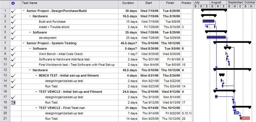
Table of Contents

                                          (Page)

Executive summary                         3,4

Block Diagram                             5

Objectives                                6

General Approach                          6,7

Contractual Aspects                       7,8

Schedules                                 8

Evaluation Methods                        8

Resources                                 9

Personnel                                 10,11

References                                11

                              2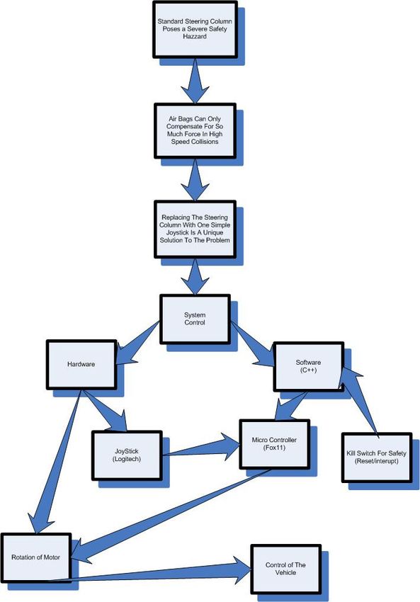
Executive Summary
In a frontal collision, the steering wheel and steering column can become a
hazard; the operator will continue to travel forward causing the operator to strike the
wheel. The upper torso and arms could impact the steering wheel causing injury varying
from bruises to broken bones. After a collision, it can become difficult for the operator to
be removed from the wrecked vehicle due to steering column intrusion into the occupant
area. By eliminating the steering wheel and column, such hazards could be avoided.
Realizing that the current generation has grown up with using a joystick to control a
video game object, using the same concept of having a joystick control the vehicle would
be an easy transition.
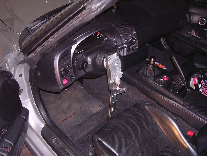
Removing the steering wheel is easily implemented by using a racing-
inspired steering hub. Once the steering wheel is removed, a pulley system will replace
the steering wheel. The pulley system will allow the use of the motor to turn the steering
shaft. With the installation of the motor next to the steering column, a joystick can
replace the steering wheel. In order for the joystick to control the motor, a
microcontroller must be used. With the mechanics in place, programming the
microcontroller will allow the inputs of the joystick to be translated to the motor. Thus
having the joystick replace the steering wheel allowing a new medium of vehicle
operation.
This process took the entire project team the entire semester to implement. When
never thought the process would be so intensive or time consuming. The first phase of
implementation began with tedious planning and purchasing of building material/parts.
Two DC electric motors were obtained and tested. It soon became apparent we needed to
3purchase an external directional control circuitry which could provide 24 volts and up to
1 amp of drive current to the steering motor. Meanwhile, the measurements for a motor
support bracket were taken and programming was being performed. The last 3 weeks was
the most intensive with all parts coming together at the same time. The motor to hub
adapter was machined and fitted to the test vehicle right as the motor bracket was being
assembled. The last couple weeks of the semester the adapter and motor support bracket
were installed onto the test vehicle to test for clearance. The last week of the semester the
programming was finally completed and everything was tested in the vehicle. The project
ended up being 3 weeks behind schedule.
Block Diagram-
The software diagram (attached below Figure 1) depicts how the software code
reads the joystick and translates this to physical movement in the motor which translates
to the front wheels of the vehicle moving in the appropriate direction and speed.
4Figure 1: Block diagram of software and it’s interaction with hardware.
5Objectives-
To produce a drive by wire steering system in which no “direct connection” is
made between the driver and the power steering rack.
Removed the vehicles steering wheel in order to reduce head and upper chest
injury in a frontal collision.
General Approach-
Hardware
The steering wheel is removed from the vehicle using an RapFix Quick-Release adapter
and a Splash Boss Steering Wheel Hub allowing access to 6 exposed hex bolt holes. A
CAD (Computer Aided Drawing) drawing was created to make CNC (Computer
Numerical Control) machining of the motor plate easier and more accurate. Two bolts
located on the vehicle floor (two front bolts holding down the drivers side seat) were
chosen to support the motor support bracket. These two bolts were chosen because of
their strength as well as relative proximity to the steering column.
The joystick, the motor, and the microcontroller are the most critical components in our
system. These three components do the majority of the control and adaptation needed for
the system to function properly. The joystick will be the input for the microcontroller and
the main control for the system. The microcontroller analyzes the signal from the joystick
compare the level to a known “look-up” table value and present the appropriate voltage
level to the motor. The motor is attached to the motor support bracket and is attached to
6the steering column of the vehicle via the CNC machined motor adapter which is bolted
to the steering shaft.
Software
The first part of the program polls the joystick waiting for the operators to move the
joystick from its stationary position. If the code is incorrectly input an error message will
be displayed on the microcontroller and the joystick will continue to be polled. Once the
correct operator’s code is input into the joystick, the code will proceed.
The first functions called will be to find the position of the motor and joystick and
appropriately calibrate to their locations. After these functions are completed, an infinite
loop will begin waiting on inputs from the joystick. The inputs from the joystick will be
compared to values in a “look-up” table. The “look-up” table will then find the
appropriate voltages to pass to the motor. Pulse width modulation will be used to rotate
the motor to the appropriate position.
There will be two options for system shutdown. The first will be an interrupt that will
restart the program from the beginning. The second would be the reset button on the
microcontroller board and will cancel control of the system disabling the control of
microcontroller. Current project plans do not call for a back-up system or another way to
regain control of the vehicle manually.
Contractual Aspects-
The vehicle is privately owned as well as all components used in the project. The vehicle
will NOT be used on public roads and thus will not require Illinois Department of
7Transportation approval. The vehicle will be tested in an open DeVry parking lot away
from other vehicles and pedestrians.
If this was an actual project for a major automotive manufacturer, legal contractual
aspects would be liability in the event of a system failure.
Schedules-
Figure 2: Schedule and Gantt chart
Evaluation Methods-
Project success or failure will be judge by task completion and overall project progress.
Attendance to project meetings is of high importance and will be regarded as critical for
project success.
8Resources-
Costs were broken down between individuals in the group for select components. Some
individuals in the group have access to discounted prices or items that are not available to
the general public (such as the motor(s) and CAD drafting software).
Part/Service Description Cost Supplier
Joystick Human to machine interface $30.00 Best Buy
Motors 24V D.C. electric motors $0.00 Free - Vending machine engineer
Motor to hub adapter Locks motor to steering shaft $0.00 Free - Made in spare time at work
Steering Wheel Hub Allows interchangeable steering wheel $190.00 www.inlinefour.com
L298 Motor Driver H-Bridge Allows digital control over motor polarity $52.95 www.hobbyengineering.com
Motor support bracket Hold motor up to steering column $30.00 Ace Hardware, Home Depot, etc
Miscellaneous Other smaller parts such as fuses, wires etc… $60.00 Radio Shack etc
Total $362.95
Figure 3: Cost breakdown chart with supplier information.
Personnel-
Brian Kosobudzki- Project Manager
Responsible for the success of the project. Responsibilities include assigning tasks to
other team members as well as project design and control. Resource management and
outsourcing tasks are critical aspect of the project manager. Project timeline management
and control are also created and managed by Brian. The CAD drafting and CNC
machining of the Motor to Hub adapter were tasks Brian undertook.
Bill Grove- Project Programmer
Programmer tasks are to design and implement the programming aspect of the project as
well as circuit design/implementation.
9Vince Sabella and Sam Aguilar- Project Design and Industrial Engineers
Purchase hardware as well as design and implement the motor support bracket. Vince and
Sam were also in charge of troubleshooting hardware problems.
References-
Dan Carney. “Scion Fuse Sports Coupe Concept.” Automotive Engineering International
June. 2006: 16
Merkle-Korff Industries. May 12 2006. Merkle-Korff Industries. May 17 2006.
Epanarama.net May 28 2002. ELH Communications LTD. May 17 2006.
www.epanorama.net/documents/joystick/pc_misc.html
Kimberly S Harnest. “Abnormal Mammogram After Steering Wheel Injury.” Western
Journal of Medicine.
http://www.pubmedcentral.nih.gov/pagerender.fcgi?artid=1022298&pageindex=1
10You can also read