Drive Doctor for Nintendo Wii
←
→
Page content transcription
If your browser does not render page correctly, please read the page content below
Drive Doctor™ for Nintendo Wii™
Installation Guide.

Warning:

Installation of Drive Doctor™ for Nintendo Wii™ requires you to have some prior
experience of soldering, and demands careful following of these instructions. If you
are at all unsure as to your ability to follow this guide correctly, seek the help of a
more experienced person.

Important warranty information:

Removing the cover of your Nintendo Wii™ console will invalidate your
warranty. If you do not want to invalidate your warranty, do not install Drive
Doctor™ for Nintendo Wii™.
Index
1. Introduction
2. Getting Started
       2.1. Pack Contents
       2.2. System Requirements
       2.3. Software Installation
3. Fitting Instructions
       3.1. Before You Begin
       3.2. Taking the Console Apart
       3.3. Fit the Drive Doctor
       3.4. Put the Console Back Together
4. Using Drive Doctor
       4.1. Introduction
       4.2. Connecting to your PC & Installing the Drivers
       4.3. Viewing and Modifying Memory
       4.4. Upgrading or Changing the Firmware
       4.5. Restoring the Original Firmware
5. Technical Support
1. Introduction
Congratulations on your purchase of Datel’s Drive Doctor™ for Nintendo Wii™.
Drive Doctor™ has been developed with electronics and programming enthusiasts in
mind. Relatively simple to install, Drive Doctor™ provides a means of accessing the
inner workings on the console’s DVD drive and data signals for diagnostics and
development purposes.
Drive Doctor™ connects to your PC via high-speed USB, and allows you to view and
modify the DVD drive’s memory in real-time. Its powerful ARM7 processor, running
at 60MHz, makes read and write operations quick and easy.
Installation of Drive Doctor™ requires knowledge and experience of soldering, whilst
its use for development or diagnostic use requires knowledge of data structures and
programming. If you don’t think you have the necessary skills, it’s strongly
recommended that you don’t continue with the installation.
Acceptable use:
Drive Doctor™ is intended to provide hobbyist programmers and enthusiasts with
access to the workings of the Nintendo Wii™ console. It is not to be used in
conjunction with any other device or software as a means of circumventing copy
protection, or for any other illegal purpose. In many countries and territories this is a
very serious matter. You have been warned.
2. Getting Started
2.1. Pack Contents
Your Drive Doctor™ for Nintendo Wii™ should contain the following parts. Please
check to make sure that everything is present. If not, please contact customer
services using the details at the end of this manual.
• Drive Doctor™ Unit
• High-Speed USB Lead
• Installation and User Manual
2.2. System Requirements
In order to install and run Drive Doctor’s PC software, please ensure you have a
computer set-up that meets the following minimum requirements:
MINIMUM SYSTEM REQUIREMENTS
Processor Pentium II or equivalent processor (Pentium IV recommended).
Ports Free USB port.
Operating System Microsoft Windows® 98 Second Edition or above (Windows® XP
recommended).Memory 256MB RAM (512MB recommended).
Install size: 10MB.
Display 800X600 SVGA or higher, True Colour.
Drive CD-ROM Drive (for installation).
2.3. Software Installation
Insert the Drive Doctor™ software CD into your PC CD-ROM drive and wait a couple
of seconds (if you have auto-run enabled) for the installation to start. If you don’t
have auto-run enabled, find the SETUP.EXE program on the CD and run it.
Follow the on-screen prompts to install the Drive Doctor™ software on your PC.
Leave the disc in your PC’s CD ROM drive ready to install the drivers when you
connect Drive Doctor™ to your PC.
3. Fitting Instructions
3.1. Before You Begin
To install Drive Doctor™, you will require the following tools:
Please DO NOT attempt installation without the correct tools as you are likely to
damage your console.
• Small ‘Tri Wing’ screwdriver - available from good console repair suppliers
for the disassembly of Nintendo consoles.
• Precision soldering iron & solder - ideally with thermostatic temperature
control.
• Small Phillips (cross headed) screwdriver - often described as a
watchmaker’s screwdriver.
• Hobby-type scalpel knife - for stripping insulation.
3.2. Taking the Console Apart
In order to solder the Drive Doctor’s fly-lead to your drive’s PCB, you need to partially
disassemble the console. In doing so, you understand that you invalidate your
console’s warranty.
Carefully follow the steps in this section, ensuring you keep all parts in a safe place
until you re-assemble the console.
1. Remove the battery compartment
• Turn the console so it’s lying flat with the back facing you. Locate the battery
compartment in the bottom-left corner on the rear of the console.
• Use the small Phillips screwdriver to remove the small threaded sliver screw.• Remove the battery compartment by gently sliding it out.
2. Reveal and remove the remaining screws on the back of the
console
• Removing the rubber foot and three rectangle stickers to reveal the screws
shown in the diagram:
• Remove the two silver, threaded Phillips-head screws from the top edge.
• Remove the black, threaded Phillips head screw from underneath the rubber
foot in the top-left corner.
• Remove the two silver, self-tapping Tri Wing screws from the bottom edge.
3. Reveal and remove the screws on the side of the console
• Lie the console on its side (with the four rubber feet facing up) and locate the
two stickers and two rubber feet shown in the diagram:• Remove the two rubber feet and two stickers shown to reveal two black and
two silver Tri Wing self-tapping screws.
• Remove all four screws. Note for the purposes of re-assembly later that the
black screws go under the stickers at the front and the silver screws go at the
back of the console underneath the rubber feet.
4. Remove the socket covers
Turn the console upright and open both socket covers. With the covers open to 90°
you should be able to remove them by gently teasing them from side to side.• Carefully remove both covers in this way.
5. Remove the memory/controller socket faceplate
• Remove the longer, black, threaded Phillips-headed screw from the nearest
the faceplate of the console.
• Remove the two smaller, black, self-tapping Phillips-headed screws from
above the GameCube™ controller and memory card ports.
• Remove the black socket faceplate.
6. Remove the screws from the memory/controller socket area• Remove the two silver, threaded screws from the top of the memory/controller
socket area.
• Remove the two silver, Tri Wing self-tapping screws from the bottom edge of
the memory/controller socket area.
7. Remove the faceplate
• Carefully remove the faceplate (the whole front of your console).
As you do so you will notice that it’s connected to the console by a small two-wire
lead. Drive Doctor™ can be installed without disconnecting this lead, but if you
would rather remove the faceplate completely, gently unplug the lead from the main
console.8. Remove the main lid
We are now ready to remove the main lid (side) of the console.
• Lie the Wii on its side so that the Nintendo and ATi logos are facing you, and
gently slide the whole side up off the console as shown in the diagram.
The fit is snug, but not tight. If the cover won’t come away easily, check to make
sure you’ve removed all the screws from previous sections.
When you remove the lid, sometimes the metal shielding comes away still attached
to the lid and other times it will stay sitting over the drive.
• If the shielding has remained on the drive (as shown in the diagram), then it
needs to be lifted off to expose the drive before you proceed to the next step.
9. Remove the drive screws
The DVD drive is attached to the rest of the console by means of four silver, Phillips-
headed, self-tapping screws with washers included.Two screws are located towards the front of the console, accessible through two holes in the top of the metal drive cover, and two more obvious points two thirds of the way towards the back of the console as both shown in the diagram. • Remove all four screws. 10. Remove the DVD drive The DVD drive now needs to be disconnected from the console.
• Gently hinge the drive away from the console, paying particular attention to
the cables attaching it to the console on the underside. Be careful not to
stress these cables.
• With the drive up at 90°, disconnect the multi-lead shown in the diagram by
easing it out from its socket.
• Next, disconnect the ribbon cable by opening the brown clip so that the ribbon
comes away with no force. DO NOT attempt to remove the ribbon cable
without opening the brown clip.
3.3. Fit the Drive Doctor
1. Prepare the Drive Doctor’s cable for soldering
In order to solder the Drive Doctor’s fly-lead to the DVD drive’s PCB, you need to trim
and strip the wires of the fly-lead.
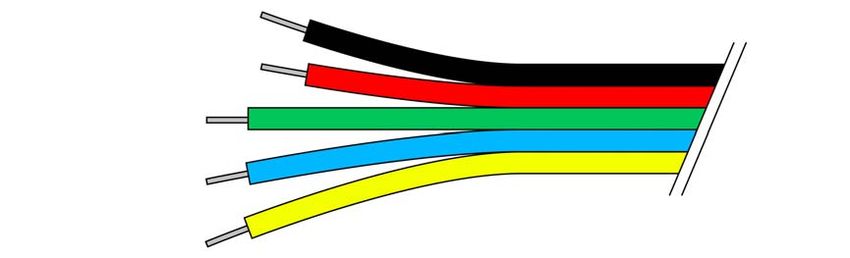
• Separate the individual leads of the fly-lead for about 15 – 20mm.
• Trim the red and black leads so that they are 5mm shorter than the yellow,
blue and green leads.
• Use a scalpel or wire stripper to remove about 3mm of insulation from the end
of the wires and then slightly twist the exposed ends.
• Use a soldering iron and solder to add some solder to the tips of the wires.2. Pass the Drive Doctor’s lead through the case.
• Pass the Drive Doctor’s fly-lead through the one of the vent holes on the back
of the console’s lid as shown in the diagram, so that it sits flush and no wire
will be visible once the installation is complete.
• For a more permanent fit, remove the backing from the sticky pad on the Drive
Doctor™ before attaching it to your console.
3. Solder the fly-lead to the underside of the DVD drive
Turn the DVD drive upside down and identify the solder points shown on the
separate colour soldering instructions card.
The solder points are located very near to the brown socket that the ribbon cable
(detached in Section 10) connects to. Make sure you match the exact solder points
indicated in the diagram.
• Carefully solder the five wires to the solder points on the circuit board. The
black and red power leads are soldered to two slightly larger pads on the
board as shown in the diagram below:
The yellow, green and blue signal carriers are soldered to slightly smaller pads on
the board. The recommended order to solder the wires is:
• BLUE, GREEN, YELLOW, RED, BLACK
Before continuing, look closely at the connections. Make sure that the wires are
properly connected to the pads (no dry joints) and that none of the wires are
interconnected.3.4. Put the Console Back Together
1. Reconnect the DVD drive and route the fly-lead
With the wires soldered in place we can now begin to put the Wii back together.
• Position the drive to the side of the console at 90°, and carefully reconnect the
ribbon cable by reinserting the connector and closing the brown clip and the
multi-lead.
• Direct the cable from the solder points towards the back of the DVD drive.
• Carefully hinge the DVD drive back down onto its mounting points with the
Drive Doctor’s fly lead coming out from underneath the DVD drive next to the
main heat-sink towards the back of the console.
Once sitting back on its mounts, you might find the DVD drive rocks ever so slightly
on the fly-lead. This is normal and will stop when the mounting screws are replaced.
• Replace the four silver, Phillips-headed, self-tapping screws (they have a
washer type head) that hold the DVD drive in place.
2. Replace the main lid
• To ensure the main lid can be replaced without obstruction, ease an excess
fly-lead into the gap in the plastic moulding to the side of the heat-sink at the
back of the console.
• If the metal shield is detached from the main lid, replace the shield over the
DVD drive.
• Gently slide the main lid back over the console. If it won’t go easily or seems
to be obstructed, adjust the routing of the fly-lead and try again.
3. Put the console back together
• Follow steps 7 back to 1 (from section 3.1) in reverse order to re-assemble the
console.
4. Using Drive Doctor
4.1. Introduction
Drive Doctor™ includes a PC application that allows you to communicate with the
device via USB, view and modify the contents of the drive’s internal and external
RAM and even write new firmware to Drive Doctor’s spare software bank.
4.2. Connecting to your PC & Installing the Drivers
In order to communicate with Drive Doctor, your Wii needs to be switched on and the
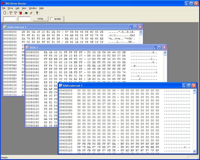
Drive Doctor™ unit needs to be connected to your PC using a USB lead (included).When you first connect Drive Doctor™ to your PC, Windows® will ask you to install the necessary drivers. The drivers are located in the root of the installation CD. Direct Windows® to this location when prompted. 4.3. Viewing and Modifying Memory The Drive Doctor™ PC software can display the data stored in 3 different types of memory on the console’s DVD Drive: Internal RAM, External RAM and the ROM (firmware). Only the Internal and External RAM are writable. Open individual windows to display the contents of these types of memory. The screen is split into columns with the memory address shown in the left hand column and the values stored at those memory locations listed in the middle columns. Use the ‘Write’ fields (normally towards the top left of the screen) to write values to specific memory locations within the active memory. The first field is used for the memory address which can be in HEX (i.e. 0x00400100) or Decimal format (4194560). The second field is for the value to write to that address. If ’16 bits’ in not checked, it is assumed that the value to be written is an 8bit value. When you click ‘Write’ the value will be instantly written to the memory location. Alternatively, values can be entered directly into memory locations in the relevant memory window.
Right click in a memory window to open the ‘Goto’ dialogue box whereby you can
jump instantly to a particular memory location.

4.4. Upgrading or Changing the Firmware
Drive Doctor™ has two software banks that can contain its boot firmware, so if
necessary, updated Drive Doctor™ firmware can be released in the future.

The first bank contains the default Drive Doctor™ firmware that the unit ships with.
This cannot be overwritten. The second bank is writable, and can contain updated
firmware (should it become available). If this bank is blank, the original firmware will
be used.

The Drive Doctor™ unit has a hardware reset button (the blue light) which can be
used to clear the second firmware bank, so you can always restore to the original
firmware should it be necessary (see section 4.5)

Upgrade the Drive Doctor’s firmware as follows:

   •   Click ‘USB’ on the menu and then choose ‘Firmware’.
   •   Make sure ‘Flash’ is selected on the firmware dialogue.
   •   Click the ‘Firmware’ button to browse for a new firmware binary.
   •   Select the binary and choose ‘OK’. The binary is written to the second bank
       on the Drive Doctor.
   •   Click the ‘Reset’ button reboot Drive Doctor™ and use the new firmware.

The new firmware will now be used automatically in place of the original firmware. If
you need to restore the original firmware, follow the instructions in the next section.

4.5. Restoring the Original Firmware
If it becomes necessary to roll back the Drive Doctor™ firmware to the original
version, follow these steps:

   •   Disable Wii Connect 24 (so the console properly powers down when switched
       off).
   •   Disconnect the USB lead (if it’s connected).
   •   Switch the console off.
   •   Press and hold the blue button on the Drive Doctor.
   •   Connect the USB cable with blue button still depressed.
   •   Switch the console on with the blue button still depressed.

Drive Doctor™ will now be using the original firmware.

5. Technical Support
If you’re experiencing difficulties any aspect of your Drive Doctor™ for Nintendo Wii™, please ensure you have read and understood the contents of this user manual before contacting Datel’s Technical Support department. When you contact Datel’s Customer Services or Technical Support department, please have ready the version number of the software you are using (normally found on the inner ring on the underside of the software disc) along with when and where you purchased the product. DATEL CUSTOMER SERVICES EUROPE: Customers Services, Datel Ltd, Stafford Road, Stone, STAFFS ST15 0DG UNITED KINGDOM Email: support@datel.co.uk Web: www.codejunkies.com DATEL CUSTOMER SERVICES USA: ATTN: Customer Services, Datel Design & Development Inc, 33 North Garden Avenue, Suite 900, Clearwater, FL 33755 Email: support@dateldesign.com Customer service knowledgebase: www.datelcustomerservice.com Main website: www.codejunkies.com
Drive Doctor™ is a 100% unofficial product and is NOT sponsored, endorsed or
approved by NINTENDO, nor any games developer or publisher.

© 2007 Datel Design & Development Ltd. Wii and GameCube are registered
trademarks of NINTENDO.
You can also read