DRONE: A Flexible Framework for Distributed Rendering and Display
←
→
Page content transcription
If your browser does not render page correctly, please read the page content below
DRONE: A Flexible Framework for Distributed
         Rendering and Display

 Michael Repplinger1,2 , Alexander Löffler1 , Dmitri Rubinstein1,2 , and Philipp
                                 Slusallek1,2
          1
           Computer Graphics Lab, Saarland University, Saarbrücken, Germany
    2
     German Research Center for Artificial Intelligence (DFKI), Agents & Simulated
                             Reality, Saarbrücken, Germany
    email: michael.repplinger@dfki.de, loeffler@cs.uni-sb.de, dmitri.rubinstein@dfki.de,
                                philipp.slusallek@dfki.de

         Abstract. The available rendering performance on current computers
         increases constantly, primarily by employing parallel algorithms using
         the newest many-core hardware, as for example multi-core CPUs or
         GPUs. This development enables faster rasterization, as well as conspicu-
         ously faster software-based real-time ray tracing. Despite the tremendous
         progress in rendering power, there are and always will be applications
         in classical computer graphics and Virtual Reality, which require dis-
         tributed configurations employing multiple machines for both rendering
         and display.
         In this paper we address this problem and use NMM, a distributed multi-
         media middleware, to build a powerful and flexible rendering framework.
         Our framework is highly modular, and can be easily reconfigured – even
         at runtime – to meet the changing demands of applications built on top
         of it. We show that the flexibility of our approach comes at a negligible
         cost in comparison to a specialized and highly-optimized implementation
         of distributed rendering.

1       Introduction

Even though the performance available for rendering on today’s hardware in-
creases continuously, there will always be demanding applications for which a
single computer is not enough, and the workload has to be distributed in a
network to accomplish the desired tasks. This demand for distribution is not
restricted to the rendering end, but also the display of rendered images fre-
quently requires distribution: be it for a multi-wall projection-based Virtual Re-
ality setup, or server-based rendering where rendering cluster and thin display
client are connected across the Internet.
    All these scenarios have something in common: they require a foundation
that is able to provide access to a maximum of available hardware resources
for their particular rendering implementation, be that in the form of processing
on a single machine, or by distribution onto several machines. There are strong
requirements for timing and synchronization as well, since the distribution of
2 Authors Suppressed Due to Excessive Length
rendering tasks and the display of their results are highly dependent on each
other and have to be done in due time and often synchronized across different
physical devices. In this paper, we present the DRONE (Distributed Rendering
Object Network) architecture as a framework solution that addresses all these
requirements. DRONE is based on NMM, a distributed multimedia middleware.
Together, DRONE supports all of the above scenarios to meet the requirements
of current and future applications.
This paper is structured as follows: in Section 2, we present related work
and derive requirements for our framework. Section 3 then provides an overview
of the basic technology of DRONE, before Section 4 explains and discusses its
architecture in more detail. Section 5 describes the versatile command language
we use for an easy setup of render graphs. Section 6 evaluates the performance
of the framework and shows that the overhead of the framework is negligible in
comparison to a highly optimized implementation. We conclude our paper and
highlight future work in Section 7.
2 Related Work
Molnar et al. [1] presented a classification scheme for distributed rendering. The
authors subdivide techniques that distribute geometry according to screen-space
tiles (sort-first), distribute geometry arbitrarily while doing a final z-compositing
(sort-last), or distribute primitives arbitrarily, but do per-fragment processing in
screen-space after sorting them during rasterization (sort-middle). This separa-
tion of techniques is based on rasterization, and where the rasterization pipeline
distributes the workload across multiple processors. It is difficult to apply the
scheme for a generic rendering and visualization architecture supporting other
techniques besides rasterization, as for example ray tracing. Here, Molnar’s clas-
sification approach is no longer applicable, as geometry processing and screen-
space projection are combined in the single operation of sampling the scene
with rays. Instead, we will discuss several typical application scenarios that our
framework should support and discuss available solution strategies.
The first application scenario (AS1), we call it single-screen rendering, com-
prises presenting rendered images on a single screen while using multiple systems
for rendering. The major demand of flexibility for (AS1) is the possibility of us-
ing available systems in the network both for rendering and displaying a scene,
while being independent of the network infrastructure connecting them. A dis-
tributed middleware like NMM provides network transparency, which in turn
allows transparent access to distributed objects, and aids in achieving this high
degree of flexibility. Another desired aspect of (AS1) is the possibility to use
different rendering techniques such as ray tracing or rasterization, all working
on the same scenes.
Previously presented frameworks for distributed rendering like WireGL [2],
and Chromium [3] are limited to the rasterization approach. The Real-Time
Scene Graph (RTSG) [4], on the other hand, provides a strict separation of
the scene graph and a specific implementation of a renderer, thus making itLecture Notes in Computer Science 3
applicable to use both rasterization and ray tracing. Equalizer [5] concentrates
on rasterization as well, but also supports ray tracing as shown in RTT’s Scale
software [6]. However, a drawback of Equalizer as well as the other rendering
frameworks is that they have fixed pipelines and do not allow flexible post-
processing of rendered images.
The second application scenario (AS2), multi-screen rendering, extends (AS1)
by splitting the resulting frame and presenting it on multiple displays simultane-
ously and fully synchronized. This is required for display walls, for example for
large-scale terrain or industrial visualization. The major desired aspect of (AS2)
is the flexibility of combining multiple displays as if they were a single one. This
also includes presenting of multiple views of the same scene at the same point
in time. For example, this is required for stereo imagery required for Virtual
Reality installations like the CAVE.
For (AS2), we need distributed synchronization to present an image simulta-
neously on all displays: hardware-based solutions, e.g., using the genlock signal of
the video output of special graphics cards [7] allow for exact frame synchroniza-
tion, while software-based solutions like NTP, are able to synchronize PCs over
the Internet with a few milliseconds of variance. We believe a flexible rendering
framework should be able to support arbitrary synchronization mechanisms.
The third application scenario (AS3) is remote rendering. It covers situations
where rendered images have to be transmitted through a network connection
with limited bandwidth, often because the original data sets have to stay at a
controlled and secure location. The main demand for of (AS3) is the ability to
add different post processing steps, e.g., the encoding of rendered images before
a network transmission. Here, the application of a distributed flow graph within
our rendering shows its full potential by providing the means to transparently
insert new processing elements in the data processing pipeline. FlowVR [8] is also
based on a flow graph but neither provides the same capability of video post-
processing nor the possibility to select transmission protocols (e.g., RTP) that
are more suitable for sending multimedia data through an Internet connection.
The last application scenario (AS4) is collaborative rendering, an arbitrary
number of combinations of the previously described scenarios. An ideal sys-
tem scenario should allow, for example, a large control center with tiled display
walls, and simultaneously thin clients only receiving some important aspects
of large rendered images. This is especially interesting for collaborative work
where people on different locations have to work with the same view of a scene.
This requires that the application is able to share the same rendered images
between multiple users while each user may be able to interact with the scene.
A similar solution to a collaborative rendering scenario is provided by the CO-
VISE [9] system. It does not transfer images but renderer-specific data making
it renderer-dependent. Also, multiplexed views for displaying are not possible.
In summary, to our knowledge, there exists no rendering framework that is
able to support all the described application scenarios.4 Authors Suppressed Due to Excessive Length 3 Overview The DRONE framework is build on the Network-Integrated Multimedia Mid- dleware (NMM) [10]. NMM uses the concept of a distributed flow graph for distributed media processing, which perfectly fits the requirement of flexibility we defined for the framework. This approach provides a strict separation be- tween media processing and media transmission as well as a transparent access to local and remote components. The nodes of a distributed flow graph represent specific operations (e.g., rendering, or compressing images), whereas edges rep- resent the transmission between those nodes (e.g., pointer forwarding for local connections, or TCP for a network connection). Nodes can be connected to each other via their input jacks and output jacks; depending on the type of operation a node implements, their numbers may vary. Nodes and edges allow the applica- tion to configure and control media processing and transmission transparently, for instance by choosing a certain transport protocol from the application layer. Prerequisite for the successful connection of two nodes is a common format, which must be identical for the output jack of the predecessor node and the input jack of the successor node to be connected. NMM incorporates a unified messaging system, which allows to send control events together with multimedia data from sources to sinks, being processed by each node in-between. 3.1 The DRONE Flow Graph The DRONE framework builds on top of an NMM flow graph consisting of custom processing nodes supplemented by existing nodes of core NMM. The ability of NMM to distribute nodes arbitrarily in the network, but still access them transparently from within an application allows the placement of applica- tion sub-tasks on arbitrary hosts, enabling high flexibility and efficient use of a cluster. Fig. 1. This flow graph shows the general idea of distributed and parallel rendering in DRONE using n rendering nodes to render to a single output device. RenderNode : A render node performs the actual rendering of a scene descrip- tion to a 2D image. Key principle of DRONE is rendering a single frame dis- tributed on multiple render nodes in the flow graph. All render nodes have access to an identical copy of the scene graph. This node renders the assigned
Lecture Notes in Computer Science       5

   scene to a memory buffer for further processing. Since NMM transparently
   supports many-core architectures, e.g., GPUs and Cell [11], rendering engines
   using many-core architectures can also be integrated into DRONE. Require-
   ments for integrating a rendering engine into DRONE are (1) the possibility
   of rendering tile frames and (2) extending a buffer into the rendering engine
   that is used for rendering.
ManagerNode : The single source node of the DRONE flow graph is called man-
   ager node; its job is to distribute the workload of rendering an image to the
   available render nodes. The manager node distributes the workload between
   render nodes by splitting the frame to be rendered into many frame tiles and
   assigning them dynamically to render nodes.
DisplayNode : A display node constitutes a sink of the flow graph, and simply
   presents any incoming image buffer synchronized according to its timestamp.
   Display nodes are part of core NMM and usually platform-dependent: for
   example, an XDisplayNode would be used on a Unix platform running the
   X window system.
TileAssemblyNode : A tile assembly node in general can receive frame tiles
   from all rendering nodes, and assembles them to a composite image buffer.
   As there is one dedicated tile assembly node for each downstream display
   node, the nodes receive only those tiles of the rendered image stream that
   are relevant for the particular display node they precede.

4     Architecture

Based on the NMM flow graph components presented in Section 3.1, DRONE
provides its functionality to the application in the form of processing blocks,
which bundle their underlying modules and provide high-level access to an ap-
plication developer. Furthermore, composite blocks allow the application to group
different processing blocks that can be treated in the same way as a single pro-
cessing block afterwards. Below, we will use the application scenarios presented
in Section 2 as a guide through the specific design decisions of the framework,
and explain how the different processing and composite blocks fit together.

4.1   Single-Screen Rendering (AS1)

The primary processing block, which occurs in every DRONE application, is
the rendering block. It contains those NMM components that are responsible for
rendering a two-dimensional image from a 3D scene: In particular, it consists of
a single manager node and at least one render node. Together, all render nodes
take care of rendering a frame. The distribution among nodes is done by tiling
the frame, and assigning single frame tiles to separate render nodes.
    The rendering block is connected to at least one presentation block, which
combines the tiles and displays the frame on an actual physical display device.
A presentation block is a composite block that can be extended by additional
nodes for post processing but contains at least two NMM nodes: a tile assembly
6 Authors Suppressed Due to Excessive Length
Fig. 2. DRONE encapsulates the flow graph in different basic processing and com-
posite blocks. The rendering block includes the manager node as well as all rendering
nodes. The presentation block includes all remaining nodes required to present ren-
dered images. GUI events received from a display node are forwarded to the render
nodes through the manager node.
node, and a display node. All those tiles of the rendered frame that are sent from
the render nodes to the corresponding assembly node have to be displayed by
the succeeding display node. Since information about the specific view is part
of the connection format between a render and tile assembly node, each render
node knows which frame tiles have to be sent to which tile assembly node. In the
trivial case of having just one display (depicted in Figure 2), the tile assembly
node receives all tiles of each frame.
DRONE also allows user interaction with the rendered scene. Because all
render nodes render the scene, each one has to be informed about user events,
such as changes to the viewpoint. In our setup, interaction events, key presses or
mouse movements, first are sent as events from the application to the manager
node. The manager node in turn forwards all incoming events to all connected
render nodes. The key point in doing so is that input events are propagated only
between tiles of different successive frames to avoid changes of viewpoint before
the processing of a single frame is fully completed.
Load Balancing The manager node is responsible for load balancing because it
sends information about the next tile to be rendered as so called tile events to its
successive render nodes. If the manager node and render nodes run in the same
address space, the manager node is directly informed by a render node about
processed tile events and the corresponding render node receives a new one as
soon as its current tile event was processed. In case of a TCP connection between
manager and a render node, DRONE configures the underlying TCP connection
such that it stores exactly one tile event in the network stack on the side of
the manager and renderer, respectively. This is possible because NMM provides
access to the underlying network connection between two nodes. As soon as the
render node starts rendering a tile event, NMM reads the next tile event from
the network stack on the side of the render node and forwards it to the node for
processing. The tile event stored in the network stack on the side of the manager
node is automatically requested by the flow control mechanism of TCP and
transmitted to the network stack on the render side. Furthermore, the managerLecture Notes in Computer Science 7
node is informed by NMM that this connection is no longer blocked and new data
can be sent through this connection. The manager node in turn sends a new tile
event to the corresponding render node such that a network connection acts as
queue of exactly three tile events. This allows DRONE to reuse the flow control
mechanism of TCP for load balancing without any additional communication
between manager node and distributed render nodes.
This simple scheduling approach leads to an efficient dynamic load balancing
between the render nodes, because render nodes that finish rendering tiles ear-
lier, do receive new rendering event earlier as well. This approach automatically
considers differences in rendering time that can be caused by different scene com-
plexity, or different processing power of different rendering machines. Moreover,
NMM informs the manager node about a failed network connection to a render
node, so that the manager node no longer tries to send tile events to this node.
All this is only possible due to the scalable transparency approach of NMM.
4.2 Multi-Screen Rendering (AS2)
Fig. 3. DRONE allows combining multiple independent presentation blocks (e.g., for
realizing video walls). The synchronized presentation of rendered images is achieved
by adding these presentation blocks into a synchronization block which then connects
a synchronizer to these presentation blocks.
The general idea to support applications that need to present rendered images
on multiple screens can be seen in Figure 4.2. The application specifies multiple
presentation blocks as well as the partial frame configuration to be displayed
by each block. All these presentation blocks are then connected to the same
rendering block by the framework. To support rendering multi-view images for
stereo or Virtual Reality scenarios, each eye is conceptually represented as a
separate presentation block. Those independent images are then treated as a
single frame and have to be presented at the identical point in time.
Synchronized presentation of rendered images is achieved by adding presen-
tation blocks to a specialized composite block, called synchronization block. This
block connects a synchronizer component to all display nodes of child presenta-
tion blocks. The synchronization block is then connected to the rendering block,8 Authors Suppressed Due to Excessive Length
while the framework automatically connects all presentation blocks to the ren-
dering block, and in doing so adds the information about the partial frame to
be presented as part of the connection format between render nodes and tile
assembly nodes. In summary, any rendered frame can be presented on any of
the screens simultaneously; either in full or in part for realizing a video wall
setup. For scenarios where blending between adjacent projectors is required, the
overlap between presentation blocks can be freely adjusted. Since our specific
synchronization component is encapsulated into a composite block, it is not
coupled with the framework itself, so that arbitrary synchronization techniques
can be integrated into DRONE by implementing a new synchronization block.
The synchronizer realized in the DRONE framework is described in [12] and
allows for synchronizing the presentation of partial or full frames in multiple
display configurations.
4.3 Remote Rendering (AS3)
Fig. 4. Extended presentation block: DRONE allows to add an arbitrary number of
postprocessing blocks to a presentation block. In this example, we first adjust brightness
and then encode rendered images before sending them through an Internet connection.
To enable sending a stream of rendered images across a high-latency network like
the Internet and still enable an interactive manipulation of the rendered scene
as described in Section 4.1, the bandwidth of the rendered raw video stream has
to be reduced drastically. The necessary reduction of the data rate is typically
done by means of encoding the image stream before sending; for example using an
MPEG-4 or H.263 video codec. Besides encoding of the stream, one can imagine
many more potential operations to be performed on the rendered images. For
instance, a color correction of neighboring projections of a video wall setup [13],
tone mapping or arbitrary other operations in pixel space.
To enable all these scenarios, we allow the insertion of one or more post-
processing blocks into a presentation block. This is automatically supported by
the framework because the presentation block is a composite block itself. Fig-
ure 4 shows a presentation block enhanced by two postprocessing blocks: one
for brightness adjustment, and one for encoding and decoding of the stream.
A postprocessing block with all its internal nodes is either inserted in front of
the tile assembly node or between the tile assembly and the display node of
any presentation block. Here, the application of a multimedia middleware likeLecture Notes in Computer Science 9
NMM, shows its full potential by providing the means to transparently insert
new processing elements in the data processing pipeline.
4.4 Collaborative Rendering (AS4)
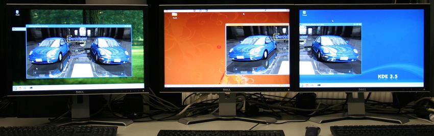
Fig. 5. Real-time ray tracing simultaneously displayed on three presentation hosts, all
of which are fully interactive and synchronized. The rendered images are displayed in
a single window on one computer (left) and a display-wall via two split video streams
on two additional machines (right).
The final application scenario to be covered by DRONE is the situation of mul-
tiple parties working on and interacting with one and the same rendering block,
realizing a collaborative environment, as for example industrial collaborations
in which 3D models are synchronously displayed to engineers in distinct offices
around the globe. In terms of the DRONE framework, this scenario represents
an arbitrary combination of (AS1) to (AS3) as presented above.
As before, the framework configuration for (AS4) includes a single rendering
block with potentially multiple presentation blocks attached. The flexible archi-
tecture of DRONE allows, for example, to realize different encoded streams for
each one of the presentation blocks, and arbitrary display setups for the partic-
ipating parties. Moreover, different applications can access and share the same
rendering block while adding their specific presentation blocks. For example, this
could be used for application scenarios where users permanently enter or leave
a collaborative virtual 3D environment. Since this scenario may incorporate ar-
bitrary rules of interaction with the scene viewpoint for different applications
written against the framework, DRONE can not define access control scenar-
ios that are appropriate purposes. Instead, we only provide access to exclusive
manipulation of the virtual camera of a single viewpoint for one presentation
block at a time. The access right to manipulate the scene is requested from
the corresponding presentation block itself. As soon as an application has re-
quested this access right, it can change the viewpoint through the interface of
the presentation block.
The possibility to realize this application scenario by combining and grouping
previously presented results again shows the high degree of flexibility of our
framework as well as the benefit for applications build on top of it.10 Authors Suppressed Due to Excessive Length
5 A Simple Command Language
To be able to easily specify and manipulate the components of a DRONE render
graph, we defined the command line application renderclic, able to play back
render graph descriptions (RGDs) defined in respective RGD files. Both appli-
cation and descriptions are inspired by the graph description format used to
specify NMM flow graphs. The RGD syntax is built upon the following context-
free grammar:
< render_graph > ::= < rendering_block > "|" < composite_blo ck >
< rendering_block > ::= < identifier > [ < method >+ ]
< composite_block > ::= < identifier > [ < method >+ ] "{" < comp osite_block >+ "}"
| < presentation_block >
< presentation_block > ::= < identifier > [ < method >+ ] [ < pre sentation_body > ]
< presentation_body > ::= "{" < postprocessing_graph > "}"
< postproc_graph > ::= < postprocessing_block > [ "|" < postp rocessing_block > ]
< postproc_block > ::= < identifier > [ < method >+ ] [ "[" < nmm_graph > "]" ]
< method > ::= " $ " < identifier > "(" < arguments > ")" < state >
< state > ::= " CONSTRUCTED " | " INITIALIZED " | " STARTED "
It defines the basic DRONE render graph (render graph) components, namely
a rendering block (rendering block), a composite block and its specialization
presentation block (composite block, presentation block). All blocks have
interfaces enabling a definition of methods (method) in an interface definition
language, as well as of the internal state (state) the block should be in upon their
execution. The RGD command language also features a direct specification of
post-processing blocks, which may contain inline NMM flow graphs (nmm graph).
Here, we omit their specification and the further resolution of identifier and
argument symbols (identifier, arguments) for brevity, though.
With the RGD language, we can define the example depicted in Figure 5,
which is real-time ray tracing rendered on two hosts and synchronously displayed
on three hosts, two of which configured in a video-wall setup. We can directly
run it with the renderclic application afterwards:
RenderingBlock $addHost (" render1 ") INITIALIZED # more re nder hosts optional
$setSceneURL ("~/ box . wrl ") INITIALIZED |
SyncBlock $setResolution (1200 , 768) INITIALIZED # used for all children
{
P r e s e n t a t i o n B l o c k $setHost (" display1 ") INITIALIZED # full frame
P r e s e n t a t i o n B l o c k $setHost (" display2 ") INITIALIZED # half frame 1
$setViewport (600 , 768) INITIALIZED # no offset here
P r e s e n t a t i o n B l o c k $setHost (" display3 ") INITIALIZED # half frame 2
$setViewport (600 , 768) INITIALIZED
$setOffset (600 , 0) INITIALIZED # viewport offset
}
6 Performance Measurements
In order to measure the overhead of our framework, we developed a rendering
node on top of RTSG and integrated OpenRT as ray tracer into RTSG which
also provides support for distributed ray tracing. As OpenRT is able to distribute
rendering in itself, our test environment allows for measuring the overhead when
DRONE is used for local or distributed rendering compared to the highly spe-
cialized implementation OpenRT.Lecture Notes in Computer Science 11
The test scene we use contains more than 1.3 million triangles and uses reflec-
tive and refractive surfaces. Each frame is rendered in a resolution of 1024x512
pixels using a fixed tile size of 64x64 pixel. Our hardware setup consists of 4 ren-
dering PCs, each equipped with two quad core Intel(R) Xeon(R) CPU 3GHz,
64GB RAM and are connected over Infiniband. In Test (1), we measure the
overhead of our flexible render graph in comparison to the monolithic rendering
application like OpenRT by rendering on a single core without any DRONE-
specific distribution. As can be seen in Table 1, DRONE achieves a frame rate
that is 0.9 % lower than the frame rate of standalone OpenRT. In order to
measure the overhead of the DRONE network communication, we gradually in-
creased in Test (2)-(5) the used cores by eight while presenting images on a
different PC. In this case, DRONE achieves a frame rate that is 1.3 % lower
than the frame rate of OpenRT. Since an overhead of 0.9 % is caused by using a
flow graph, the overhead caused by the network communication has an influence
of 0.4 % on the frame rate. We then perform the same tests but with a second
presentation block in DRONE in order to show the overhead of the synchroniza-
tion mechanism. However, when using two presentation blocks, presenting half
of each frame, no additional overhead of the synchronization is introduced.
From our point of view, both performance and memory overhead intro-
duced by DRONE are negligible, because applications greatly benefit when using
DRONE due to the flexibility of the framework.
Test Cores OpenRT DRONE
1 Display 1 Display 2 Displays
(1) 1 0.434 fps 0.43 fps 0.43 fps
(2) 8 3.14 fps 3.10 fps 3.10 fps
(3) 16 6.05 fps 5.93 fps 5.93 fps
(4) 24 9.08 fps 8.97 fps 8.97 fps
(5) 32 12.12 fps 12.00 fps 12.00 fps
Table 1. Performance results using standalone OpenRT vs. OpenRT integrated in
DRONE. Frame rate is measured when presenting images on a single display as well
as on two displays, each presenting half of the frame.
7 Conclusion and Future Work
In this paper we presented the DRONE architecture, an application development
framework for distributed rendering and display. Using NMM as an underlying
communication architecture provides an unprecedented flexibility in parallelizing
and distributing all aspects of a rendering system: user input, load-balancing,
rendering, post-processing, display, and synchronization. By designing a small
set of modules that can be combined easily, an application can flexibly configure
distributed rendering and display – even dynamically during runtime. As shown12 Authors Suppressed Due to Excessive Length
in Section 6, this flexibility comes at a negligible cost over specialized and highly
optimized implementations of the same functionality.
In the future, we want to explore ways to even further make use of all hard-
ware resources available for rendering in the network. We plan to integrate next-
generation multi-core technologies such as the CUDA and Cell architectures in
our rendering pipelines.
References
1. Molnar, S., Cox, M., Ellsworth, D., Fuchs, H.: A Sorting Classification of Parallel
Rendering. IEEE Computer Graphics & Applications 14 (1994) 23–32
2. Humphreys, G., Eldridge, M., Buck, I., Stoll, G., Everett, M., Hanrahan, P.:
WireGL: a Scalable Graphics System for Clusters. In: SIGGRAPH ’01: Proceedings
of the 28th Annual Conference on Computer Graphics and Interactive Techniques.
(2001) 129–140
3. Humphreys, G., Houston, M., Ng, R., Frank, R., Ahern, S., Kirchner, P.D.,
Klosowski, J.T.: Chromium: a Stream-Processing Framework for Interactive Ren-
dering on Clusters. In: SIGGRAPH ’02: Proceedings of the 29th Annual Conference
on Computer Graphics and Interactive Techniques. (2002) 693–702
4. Rubinstein, D., Georgiev, I., Schug, B., Slusallek, P.: RTSG: Ray Tracing for X3D
via a Flexible Rendering Framework. In: Proceedings of the 14th International
Conference on Web3D Technology 2009 (Web3D Symposium ’09), New York, NY,
USA, ACM (2009) 43–50
5. Eilemann, S., Pajarola, R.: The Equalizer Parallel Rendering Framework. Technical
Report IFI 2007.06, Department of Informatics, University of Zürich (2007)
6. Technology, R.: Rtt scale homepage (2009) http://www.realtime-technology.com/.
7. NVIDIA Corporation: NVIDIA Quadro G-Sync.
(http://www.nvidia.com/page/quadrofx gsync.html)
8. Arcila, T., Allard, J., Ménier, C., Boyer, E., Raffin, B.: FlowVR: A Framework For
Distributed Virtual Reality Applications. In: 1iere journées de l’Association Fran-
caise de Réalité Virtuelle, Augmentée, Mixte et d’Interaction 3D, Rocquencourt,
France (2006)
9. Rantzau, D., Lang, U., Lang, R., Nebel, H., Wierse, A., Ruehle, R.: Collabo-
rative and Interactive Visualization in a Distributed High Performance Software
Environment. In Chen, M., Townsend, P., Vince, J.A., eds.: Proceedings of the
International Workshop on High Performance Computing for Graphics and Visu-
alization, Springer (1996) 207–216
10. Lohse, M., Winter, F., Repplinger, M., Slusallek, P.: Network-Integrated Multime-
dia Middleware (NMM). In: MM ’08: Proceedings of the 16th ACM international
conference on Multimedia. (2008) 1081–1084
11. Repplinger, M., Beyer, M., Slusallek, P.: Multimedia Processing on Many-Core
Technologies Using Distributed Multimedia Middleware. In: Proceedings of The
13th IASTED International Conference on Internet and Multimedia Systems and
Applications (IMSA ’09) (to appear). (2009)
12. Repplinger, M., Löffler, A., Rubinstein, D., Slusallek, P.: URay: A Flexible Frame-
work for Distibuted Rendering and Display. Technical Report 2008-01, Department
of Computer Science, Saarland University, Germany (2008)
13. Kresse, W., Reiners, D., Knöpfle, C.: Color Consistency for Digital Multi-Projector
Stereo Display Systems: the HEyeWall and the Digital CAVE. In: EGVE ’03:
Proceedings of the workshop on Virtual environments 2003. (2003) 271–279You can also read