SPICE Module User's Guide - Powersim Inc - Powersim, Inc
←
→
Page content transcription
If your browser does not render page correctly, please read the page content below
SPICE Module
                  User’s Guide

                     Powersim Inc.

Chapter :                            -3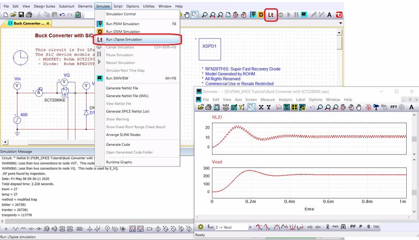
SPICE Module User’s Guide
Version 2020a
Release 1

May 2020

Copyright © 2016-2020 Powersim Inc.
All rights reserved. No part of this manual may be photocopied or reproduced in any form or by any means without the written
permission of Powersim Inc.

Disclaimer
Powersim Inc. (“Powersim”) makes no representation or warranty with respect to the adequacy or accuracy of this
documentation or the software which it describes. In no event will Powersim or its direct or indirect suppliers be liable for any
damages whatsoever including, but not limited to, direct, indirect, incidental, or consequential damages of any character
including, without limitation, loss of business profits, data, business information, or any and all other commercial damages or
losses, or for any damages in excess of the list price for the licence to the software and documentation.

Powersim Inc.

Email: support@powersimtech.com
powersimtech.com

-2                                                                                                                     Chapter :
Contents

1      Introduction
      1.1   Setup for SPICE simulation    1
      1.2   Run SPICE Simulation      2

2      PSIM-SPICE Interface
      2.1   SPICE Directive Block     3
      2.2   SPICE Model Libraries    4
            2.2.1 SPICElib Folder     4
            2.2.2 Search Paths for SPICE Models     4
            2.2.3 Finding SPICE Models in Libraries   5
            2.2.4 Using SPICE Models not in Libraries   5
      2.3   Simulation Control for SPICE Simulation   5
            2.3.1 Transient Analysis     6
            2.3.2 AC Analysis       7
            2.3.3 DC Analysis       8
            2.3.4 Step Run Option      9
            2.3.5 Other Analysis Options     9
      2.4   PSIM Elements for SPICE Simulation   10
            2.4.1 Multi-Level Elements     10
            2.4.2 SPICE Subcircuit Netlist Block  11
            2.4.3 AC Analysis for Switch-Mode Circuits      12
            2.4.4 Capacitor (V Controlled)    13
      2.5   Create PSIM Element from SPICE Netlist    14

3      SPICE Analysis Directives
      3.1   Overview    18
      3.2   Convergence Issue    18
      3.3   SPICE Analysis Types     18
            3.3.1 .AC     18
            3.3.2 .DC     18
            3.3.3 .END      19
            3.3.4 .ENDS       19
            3.3.5 .FOUR       19
            3.3.6 .FUNC       19
            3.3.7 .GLOBAL        20
            3.3.8 .IC    20
            3.3.9 .INCLUDE        20
            3.3.10 .LIB    20
            3.3.11 .MODEL       21
            3.3.12 .OP    21
            3.3.13 .OPTIONS      21
            3.3.14 .PARAM       22
            3.3.15 .SAVE     24
            3.3.16 .STEP     24

Chapter :                                                         i
                                                                 -1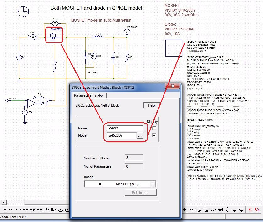
3.3.17 .SUBCKT    25
            3.3.18 .TEMP   25
            3.3.19 .TRAN   25

4     SPICE Elements and Device Models
      4.1   Overview      27
      4.2   Passive Elements  28
            4.2.1 Resistor   28
            4.2.2 Capacitor   28
            4.2.3 Inductor   28
            4.2.4 Coupled Inductor        29
      4.3   Transmission Lines  30
            4.3.1 Lossless Transmission Line  30
            4.3.2 Uniform Distributed RC Line   30
      4.4   Active Elements   31
            4.4.1 Voltage-Controlled Switch      31
            4.4.2 Current-controlled switch     31
            4.4.3 Controlled Switch Model      32
            4.4.4 Diode     32
            4.4.5 Bipolar Junction Transistor (BJT)    33
            4.4.6 MOSFET       33
            4.4.7 Junction Field-Effect Transistor (JFET)       34
            4.4.8 MESFET       34
      4.5   Sources  35
            4.5.1 Independent voltage and current sources       36
                    4.5.1.1 Pulse    36
                    4.5.1.2 Sinusoidal    37
                    4.5.1.3 Exponential    37
                    4.5.1.4 Piece-Wise Linear     37
                    4.5.1.5 Single-Frequency FM        38
                  4.5.1.6 Wavefile  38
            4.5.2 Linear Dependent Sources        38
                    4.5.2.1 Voltage-Controlled Voltage Source        38
                    4.5.2.2 Voltage-Controlled Current Source        39
                    4.5.2.3 Current-Controlled Voltage Source        39
                    4.5.2.4 Current-Controlled Current Source   39
            4.5.3    Nonlinear Dependent Sources (Behavioral Sources)     40
            4.5.4    Special Functions  40

5      References

ii0                                                                            Chapter :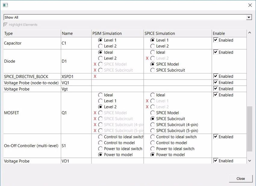
1
Introduction
The SPICE Module is an add-on option of the PSIM software. It provides a link to the LTspice1 software, and
allows user to create a circuit schematic in the PSIM environment, and run LTspice simulation by simply
clicking on the button "Run LTspice Simulation". It also provide the option to read netlists generated from other
sources, as long as the netlists are in LTspice format.
Features of the SPICE Module include:
• Support of LTspice simulation in the PSIM environment.
• Accommodation of component models from manufacturers and other sources.
• Generation of LTspice netlist for simulation.
This manual describes how to use the SPICE Module, and provides essential information for SPICE analysis,
elements, and models.
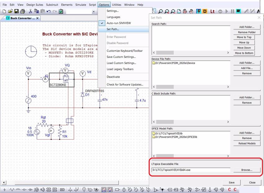
1.1 Setup for SPICE simulation
Before running LTspice simulation, user must install LTspice on the computer, and specify the location of
LTspice executable file by selecting Options >> Set Path. At the bottom of this dialog, as shown in the picture
below, user the Browse button to find and enter the path and filename for the LTspice executable file. Then,
click Save and close the dialog.
1. LTspice is copyright by Analog Devices Inc., 1998-2020
Chapter 1: Introduction 1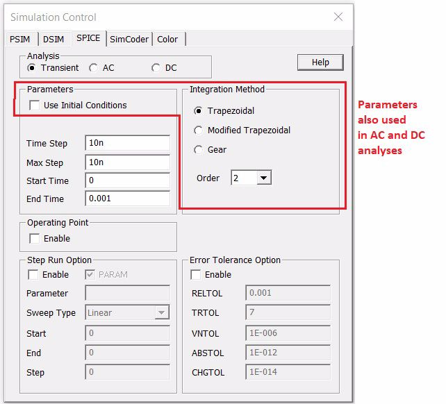
1.2   Run SPICE Simulation
      To run LTspice simulation, click on the button Run LTspice Simulation on the tool bar or select Simulate >>
      Run LTspice Simulation from the pull-down menu, as indicated below.
      The simulation runs entirely inside the LTspice engine.

      At the start of LTspice simulation, the content of LTspice’s ".log" file will be displayed in the Simulation
      Message window. During the time while simulation is running, there is no status or progress information passed
      from LTspice to PSIM. Therefore, the messages in this window can not be updated.
      At the end of simulation, the simulation result will be displayed in SIMVIEW. The Simulating Message
      window will refresh with the content from the .log file generated by LTspice.
      If the LTspice engine encounters an unsolvable situation during simulation, such as convergence failure or a bug
      in its code, as long as LTspice does not stop simulation, PSIM can not stop LTspice. In such cases, users must
      stop LTspice simulation. from the Windows Task Manager.

2                                                                                               Chapter 1: Introduction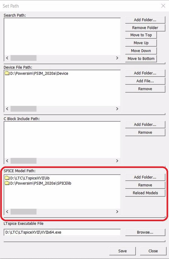
2
                                                                             PSIM-SPICE Interface

        The SPICE Module provides functions to integrate SPICE models into the PSIM environment.

2.1      SPICE Directive Block
        The element "SPICE Directive Block" is provided to allow users to write SPICE commands, options, models,
        subcircuit netlist, parametric attributes, and other directives which are not implemented by PSIM schematic.
        This block can be found in Elements >> SPICE >> SPICE Directive Block.
        Only one SPICE Directive block is allowed in each schematic. Therefore, all the SPICE directives must be
        collected together in one block. In the netlist generated by PSIM, the content of this block will be placed at the
        top of the file.
        The figure below is an example of a SPICE Directive Block with some netlist content. One can or copy and
        paste the netlist into this block. The button "Save to File" allows users to save the content of this block into a
        text file.

        Since simulation runs in the LTspice engine, the model netlist files must conform to LTspice netlist syntax. If
        SPICE netlist files were generated for other SPICE software, they may contain syntaxes which are not accepted
        by LTspice.
        We have provided a function for users to check and convert the netlist syntaxes into what can be accepted by
        LTspice. This function is inside of the element "SPICE Directive Block".
        The button "Check Syntax" in the SPICE Directive Block will help users to check the netlist against LTspice
        format. It will open the "SPICE Netlist Check" dialog.
        In the "SPICE Netlist Check" dialog, the original netlist statements are on the left hand side and the LTspice
        acceptable netlist statements are on the right hand sides.
          • The lines highlighted in blue indicate those statements have minor syntax difference and PSIM has
             converted those statements into LTspice format.

Chapter 2: PSIM-SPICE Interface                                                                                         3
• The lines highlighted in yellow indicate those statements have no compatible conversion. It could be a
         function that LTspice do not support. User must convert those statements and rewrite them manually.
      One can also use the "Load" button to load other netlist files and check the syntax.

2.2   SPICE Model Libraries
      PSIM can load device models in SPICE netlist form directly. Even the encrypted models can be used. The
      libraries of the SPICE models are managed in the following ways.

2.2.1 SPICElib Folder
      PSIM comes with a model library which contains SPICE netlist files. These models are stored in the subfolder
      "SPICElib". Users may add into this folder the netlist files containing models written by themselves or from
      manufacturers.

2.2.2 Search Paths for SPICE Models
      To utilize pre-existing SPICE netlist files stored in locations other than the SPICElib folder, the search path
      must be properly set.
      Select Options >> Set Path. On the dialog, in the section for "SPICE Model Path", specify or add the locations
      of the SPICE library files, as shown below. Remember to Reload Models and Save the path settings before
      closing the dialog.

4                                                                                     Chapter 2: PSIM-SPICE Interface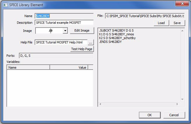
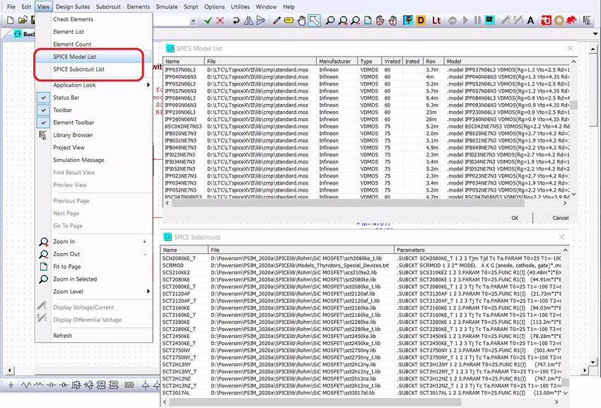
2.2.3 Finding SPICE Models in Libraries
        All the models in the files in the search path folders are loaded into PSIM. To check if the search path is set
        correctly and what models are available, select View >> SPICE Model List or View >> SPICE Subcircuit
        List, as shown below

2.2.4 Using SPICE Models not in Libraries
        If the models are not found in the SPICE libraries and search paths, one must use the SPICE Directive Block as
        explained in Section 2.1 SPICE Directive Block.
        In this block, one can write (copy & paste) the netlist for SPICE models.
        If one prefers to store the model netlist files in a location other than in one of PSIM’s search paths, the
        “.include” command must be included in the "SPICE Directive Block".
            .include \
        If the models are encrypted, such as in ".lib", no matter whether the files are in the PSIM search
        paths or not, one must write the ".lib" command in the SPICE Directive Block as below:
             .lib \.lib
        This is because the name of the models and subcircuits are also encrypted in such files. PSIM can not un-
        encrypt those names, and hence, can not find them in the search paths.

2.3      Simulation Control for SPICE Simulation
        SPICE simulation has three basic analyses: transient analysis, AC analysis, and DC analysis. Simulation control
        parameters and options are defined in the Simulation Control dialog, under the SPICE tab, as explained in the
        following subsections.
        For SPICE analysis and options not included in the Simulation Control dialog, one must write SPICE
        commands and define the options in the "SPICE Directive Block".

Chapter 2: PSIM-SPICE Interface                                                                                      5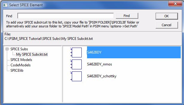
2.3.1 Transient Analysis
     For transient analysis, the Simulation Control dialog define the following parameters:
       Use Initial Conditions:   If the box is checked, the "UIC" option is added to the .tran command.
                                 Note: This setting also affects AC and DC Analysis.
       Time Step:                Suggested time step Tstep, in second.
       Max Step:                 The maximum step size Tmax that SPICE uses, in second. By default, it chooses
                                 either Tstep or (Tend-Tstart)/50, whichever is smaller. Tmax is useful when one
                                 wishes to guarantee a computing interval which is smaller than Tstep.
       Start Time:               The initial time Tstart, in second. The transient analysis always begins at time zero.
                                 In the interval from zero to tstart, the circuit is analyzed (to reach a steady state),
                                 but no outputs are stored.
       End Time:                 The final time Tend, in second.
       Integration Method        The numerical integration methods used by SPICE. Choices are: Trapezoidal,
                                 Modified Trapezoidal, and Gear.
                                 Note: This setting also affect AC and DC Analysis.
       Order                     The order for the numerical integration method. Available values for Trapezoidal
                                 method are 1 and 2. Available values of Gear method are from 2 to 6.
     Some of these parameters are also used for AC and DC analyses, although they do not show in those settings.

6                                                                                      Chapter 2: PSIM-SPICE Interface
2.3.2 AC Analysis
For AC analysis, the Simulation Control dialog defines the following parameters:
Sweep Type Defines the sweep types. The options are: Octave, Decade, Linear, or List.
Parameters for the Octave or Decade option:
Start Freq: Starting frequency, in Hz.
End Freq: Final frequency, in Hz.
Points/oct (or dec): Number of points per octave or decade.
Parameters for the Linear option:
Start Freq: Starting frequency, in Hz.
End Freq: Final frequency, in Hz.
Points: Total number of points.
Parameters for the List option:
Freq List: A list of frequencies to be analyzed, in Hz. Each value is separated
with a space.
Chapter 2: PSIM-SPICE Interface 72.3.3 DC Analysis
For DC analysis, the Simulation Control dialog accepts the following parameters:
Name Name of the source for DC sweep. Source 1 is by default the x-axis. Source 2 can
be enabled. The DC sweep sources can be voltage, current, or temperature.
Sweep Type Defines the sweep types. The options are: Octave, Decade, Linear, or List.
Parameters for the Octave and Decade options:
Start: Starting value.
End: Final value.
Points/oct (or dec): Number of points per octave or decade.
Parameters for the Linear option:
Start: Starting value.
End: Final value.
Increment: Incremental step size.
Parameters for the List option:
List: A list of values to be analyzed. Each value is separated with a space.
8 Chapter 2: PSIM-SPICE Interface2.3.4 Step Run Option
If enabled, SPICE simulation would run a parameter sweep.
Parameter Name of the parameter for Step Run. If the step run is NOT for a voltage or a
current source, or temperature, the box "PARAM" must be checked.
Sweep Type Defines the sweep types. The options are: Octave, Decade, Linear, or List.
Parameters for the Octave and Decade options:
Start: Starting value.
End: Final value.
Points/oct (or dec): Number of points per octave or decade.
Parameters for the Linear option:
Start: Starting value.
End: Final value.
Step: Incremental step size.
Parameters for the List option:
List: A list of values to be analyzed. Each value is separated with a space.
2.3.5 Other Analysis Options
The Simulation Control dialog also defines the following analysis options:
Operating Point: If enabled, SPICE simulation will determine the DC operating point of the circuit
with inductors shorted and capacitors opened.
Step Run Option: If enabled, SPICE simulation would run a parameter sweep.
Parameter: The name of the parameter to sweep
Start: Starting value
Step: Incremental value
End: Final value
Error Tolerance Option: If enabled, the tolerance values for SPICE simulation can be set manually.
RELTOL: Relative error tolerance of the program.
TRTOL: Transient error tolerance.
VNTOL: Absolute voltage error tolerance of the program
ABSTOL: Absolute current error tolerance of the program
CHGTOL: Charge tolerance of the program
For SPICE analyses and options not included in the Simulation Control dialog, one must write SPICE
commands and define the options in the "SPICE Directive Block".
Chapter 2: PSIM-SPICE Interface 92.4 PSIM Elements for SPICE Simulation
Many PSIM schematic elements are supported for SPICE simulation. One can set PSIM’s display option to see
which elements are supported. In the menu Options >> Settings >> Advanced, check the box Show image next
to elements that can be used for SPICE. With this box checked, the elements supported by SPICE will be
marked with the image .
The SPICE netlist implementation of PSIM elements imitates the PSIM element characteristics. For example, if
the element Resistor’s Model Level is selected as Level 1, its corresponding SPICE netlist is a single resistor; if
it is selected as Level 2, its corresponding SPICE netlist would contain a resistor with a series inductor and a
parallel capacitor.
2.4.1 Multi-Level Elements
Most of the marked elements can be used both in PSIM simulation and in SPICE simulation. However,
some elements have multi-level options. Some levels may be used for both PSIM and SPICE simulation; some
levels are for PSIM only while others are for SPICE only.
The advantage of multi-level elements is that, one can specify the level for desired simulation, and hence, the
same schematic can run in both PSIM simulation and SPICE simulation.
For example, the element Power >> Switches >> MOSFET is a multi-level element. It has the following
model levels:
• Ideal: Can be used in both PSIM and SPICE simulation.
• Level 1: For SPICE simulation only.
• Level 2: For PSIM simulation only.
• SPICE Model: For SPICE simulation only.
• SPICE Subcircuit: For SPICE simulation only, 3-node: drain, gate, source
• SPICE Subcircuit (4-pin): For SPICE simulation only, 4-nodes: drain, gate(+), gate(-), and source
• SPICE Subcircuit (5-pin): For SPICE simulation only, 5-nodes: drain, gate, source, temp(+), and temp(-).
One can check the box "Select different element models for simulation" in the "Simulation Models" tab in this
MOSFET’s parameter dialog, and specify different levels for "PSIM Model" and for "SPICE Model".
To help users checking if correct model level is selected for desired simulation, the function View >> Check
Elements is provided. It will list elements in the circuit, as shown below.
10 Chapter 2: PSIM-SPICE InterfaceThe list can show different types of elements by selecting the options from the drop-down menu:
• Show all: List all the elements in the schematic.
• Show only multi-level elements: List only multi-level elements, and show the model level selected for PSIM
simulation or SPICE simulation.
• Show only elements that are not compatible with PSIM simulation: List only the elements which are not
supported for PSIM simulation.
• Show only elements that are not compatible with SPICE simulation: List only the elements which are not
supported for SPICE simulation
If the checkbox Highlight Elements is checked, all the elements listed in display will be highlighted in the
schematic.
The model levels of multi-level elements can be changed here directly, and it has the same effect as if they were
changed through the property dialog window.
Elements can be enabled/disabled by checking/unchecking the Enable checkbox.
With this function, one can quickly identify and replace the elements which are not supported by the desired
simulation engine.
2.4.2 SPICE Subcircuit Netlist Block
PSIM provides the element "SPICE Subcircuit Netlist Block" for users to create or to use existing SPICE
subcircuit netlist in PSIM. This block can be found in the menu Elements >> SPICE >> SPICE Subcircuit
Netlist Block.
This block generates a calling statement to the subcircuit. In this block, one can specify the subcircuit’s name,
number of nodes, parameter names, and parameter values. The definition and content of the subcircuit must be
provided by either browsing the subcircuit files or writing in the SPICE Directive Block.
The subcircuit syntax in the SPICE Directive Block must follow SPICE netlist format for subcircuit, starting
with .SUBCKT and ending with .ENDS. One should always check the netlist for SPICE netlist syntax errors
before running simulation.
For the example shown in the picture below, in the SPICE netlist, the calling of the subcircuit in SPICE netlist
is:
XSPS2 3 5 10 Si4628DY
And the subcircuit content will be the same as written in the SPICE Directive Block:
.SUBCKT Si4628DY D G S
X1 D G S Si4628DY_nmos
X2 S D Si4628DY_schottky
.ENDS Si4628DY
...
...
Chapter 2: PSIM-SPICE Interface 112.4.3 AC Analysis for Switch-Mode Circuits
LTspice can perform small signal AC analysis of a linear circuit. However, it cannot perform ac analysis if the
circuit is nonlinear, such as a switch-mode converter circuit.
PSIM overcomes this limitation by performing transient simulation with small signal AC perturbation over a
range of frequencies and calculating the ac sweep response in the end.
For detailed procedure, please refer to "Tutorial - AC Analysis of Switch-Mode Models in LTspice
Simulation.pdf".
Three elements are created for this purpose:
AC Sweep (1 probe): AC sweep excitation source with one response probe
AC Sweep (2 probes): AC sweep excitation source with two response probes
AC Sweep (loop): AC sweep excitation source with a loop response probe
Images:
AC Sweep (1 probe) AC Sweep (2 probes) AC Sweep (loop)
12 Chapter 2: PSIM-SPICE InterfaceAttributes:
Parameters Description
Peak Amplitude Amplitude of AC excitation, in V.
DC Offset DC offset of the AC excitation source, for steady state operation point, in V. This
parameter is not used in AC Sweep (loop).
Notes:
The nodes connecting to these elements must be named using Edit >> Set Node Name. This is because the
method used for the calculation of the frequency response in LTspice needs the net names to be predefined.
• The node connecting to the "Source" must be named "ACS".
• The node connecting to the "Response" must be named "ACR".
• For AC Sweep (loop), the nodes connecting to the two "Responses" must be named "ACR1" and "ACR2".
The Simulation Control for AC analysis of switching mode circuit must be set up as Transient Analysis with
Step Run to sweep the frequency of the AC excitation signal, as shown below
The "Start Time" for the transient analysis is pre-estimated time when the circuit reaches steady state operation.
2.4.4 Capacitor (V Controlled)
This is a nonlinear capacitor model. The capacitance is controlled by the voltage across it.
Images:
Chapter 2: PSIM-SPICE Interface 13There are three model types:
Model A: This model is a current source. The input node "Ct" controls the capacitance.
Ct= Q/V.
Model B: This model is a voltage source. The input node "Ct" controls the capacitance.
Ct= Q/V.
Model Cd: This model is s a current source. The input node "Cd" controls the capacitance.
However, Cd=dQ/dV (not Q/V).
Note:
The signal connected to "Ct" or "Cd" can be either from a nonlinear expression of the voltage across the
capacitor, or from a lookup table output.
2.5 Create PSIM Element from SPICE Netlist
Users may have accumulated many subcircuit netlists from previous works or from manufacturers’ model
database. PSIM provides a convenient way for users to utilize those pre-existing netlists. One may create and
maintain a SPICE element library as part of the PSIM schematic element library.
Before the SPICE subcircuit elements can be entered into a PSIM element library, the path for the SPICE
subcircuit netlist files must be included in PSIM’s search path.
Once the SPICE netlist file is entered into PSIM search path, one should remove it from the SPICE Directive
Block in the circuit schematic.
A SPICE subcircuit element library can be created and maintained in the same way as an element in PSIM
library. The following information are needed to create a PSIM library element from a SPICE subcircuit netlist:
Name The name of the subcircuit, must be the same as in the .subckt line in the netlist.
Description A short description of the subcircuit.
Image One can use PSIM’s Image Editor and define the subcircuit's image size and port
positions connecting to main circuit. PSIM provides a few standard semiconductor
images. Make sure the port sequence is the same as in the subcircuit netlist.
Help File The link to the optional html help file of the subcircuit.
Ports A list of port names/numbers as defined in the netlist's .subckt statement.
Parameters List of parameters and default values, must be the same as in the .subckt or .param
statement.
File The name of the subcircuit file.
For example, if a SPICE netlist file "My SPICE Subckt.txt" contains some SPICE subcircuit netlists, and it is
saved in the folder "C:\PSIM_SPICE Tutorial\SPICE Subs". To create a new library which contains those
subcircuits:
• Include the folder "C:\PSIM_SPICE Tutorial\SPICE Subs" in the PSIM’s SPICE model search path.
• In the menu Edit >> Edit Library >> Edit Library Files, select New Library to create a new library for
SPICE subcircuit elements.
• Type the library name to be displayed in PSIM's "Elements" menu as "User SPICE Elements".
• Type the library file name: "My SPICE File". Click OK to add this new file into the library list.
• Select this new library name "My SPICE File.lib", then, click the button for "Edit Selected Library". The
image library editor would open as shown below.
14 Chapter 2: PSIM-SPICE Interface• Click the button for "New SPICE Element". All the models and subcircuits in the files which already are
put into the PSIM searching path would be displayed.
• Double click the file name "My SPICE Subckt.txt" and all the subcircuits in this file would show.
Chapter 2: PSIM-SPICE Interface 15• Double click on "Si4628DY", the editor for SPICE Library Element would open. In this editor, the
subcircuit's definition, name, nodes, and parameters and their default values are parsed automatically.
• Write an optional brief description "SPICE Tutorial example MOSFET".
• Select the MOSFET image from the image list. Please make sure the node sequence in the image is the
same as in the subcircuit definition.
• If a new image is desired, click "Edit Image" to edit this element's image: to set the size, to locate the nodes,
to add texts, and to draw graphic designs for the image.
• It is optional to create a html formatted help file name "SPICE Tutorial MOSFET Help.html" in the folder
"Powersim\Help", type the help file name in the space provided, and click the button "Test Help Page" to
verify the link.
• Click "Save" button to save the element in the library, and click "OK" to close the SPICE element editor.
• In the Image Library editor, the new element "Si4628DY" is shown now.
16 Chapter 2: PSIM-SPICE Interface• Click "Save Image Library" to update the library, then, click "Update Menu" button to update the Elements
menu for the display of this newly created element.
• Now this new PSIM element is ready to be used for in the schematics for SPICE simulation.
• To insert this newly created element in a schematic for SPICE simulation, simply click on Elements >>
User SPICE Elements >> Si4628DY, place it in the proper location in the schematic, and connect the
wires.
Chapter 2: PSIM-SPICE Interface 173
SPICE Analysis Directives
3.1 Overview
PSIM creates netlists in standard LTspice syntax. For more information on LTspice syntax, refer to [1]. For
general SPICE syntax, refer to [2-3].
This chapter describes SPICE directives related to analysis types, commands, and options. These directives can
also be directly added to the netlist to run the relevant analyses.
3.2 Convergence Issue
Sometimes SPICE simulation does not converge. When this occurs, one can try to change the type of the
numerical integration algorithm, or adjust the error tolerance values, or add snubber circuits to switches.
3.3 SPICE Analysis Types
All the analysis types and options supported in LTspice are supported by the SPICE module, as listed below.
More details and extensive documentation is available on line [4].
The simulator supports the following different types of analysis:
• AC Small-Signal Analysis
• DC Analysis (Operating Point and DC Sweep)
• Transient Analysis
3.3.1 .AC
Perform a small signal AC analysis linearized based on a dc operating point.
Syntax:
.ac
Examples:
.ac dec 10 1 10k
.ac lin 100 1 100
Keyword Description
oct/dec/lin Specify if the analysis is in octave, decade, or linear variation
Nsteps Number of steps in each octave, decade, or total number of linearly spaced steps
between the starting and final frequency.
StartFreq Starting frequency
EndFreq Final frequency
3.3.2 .DC
Perform dc analysis while sweeping the dc value of a source. It is useful for plotting the characteristic curves of
an electronic component.
Syntax:
.dc [ ]
Examples:
18 Chapter 3: SPICE Analysis Directives.dc Vds 3.5 0 -0.05 Vgs 0 3.5 0.5
Keyword Description
srcnam Name of the independent source that is to be swept. it can be a voltage or current
source.
Vstart Starting value for the sweep
Vstop Final value for the sweep
Vincr Incremental step value for the sweep
3.3.3 .END
It marks the end of the netlist. All data and every other command must come before it. All lines after this is
ignored.
Syntax:
.END
3.3.4 .ENDS
It marks the end of a subcircuit definition. See.SUBCKT for more information
Syntax:
.ENDS
3.3.5 .FOUR
This command controls whether SPICE performs a Fourier analysis as a part of the transient analysis. The
Fourier analysis is performed over the one period interval before the transient analysis’ final time.
Syntax:
.four [Nharmonics] [Nperiods] [ ...]
Example:
.four 1kHz V(out)
Keyword Description
frequency Fundamental frequency
Nharmonics The number of harmonics to be included in analysis
Nperiods The number of period to be included in analysis, from the end.
data trace Variable to be analyzed
3.3.6 .FUNC
This directive allows the creation of user-defined functions for behavioral sources.
Syntax:
.func ([args]) {}
Example:
.func Pythag(x,y) {sqrt(x*x+y*y)}
Keyword Description
Fname Function name
args Arguments in the function
expression Mathematical expression of the function
Chapter 3: SPICE Analysis Directives 193.3.7 .GLOBAL
This statement declares the nodes which are available to all circuit and subcircuit blocks independent from any
circuit hierarchy.
Syntax:
.global [node2 [node3] [...]]
Example:
.global VDD VCC
Keyword Description
node1, node2, node3 ... The nodes defined as global, to be accessible from the top level.
3.3.8 .IC
This line sets initial conditions for transient analysis.
Syntax:
.ic [V()=] [I()=]
Example:
.ic V(in)=2 V(out)=5 V(vc)=1.8 I(L1)=300m
Keyword Description
V()= Initial node voltage settings
I()= Initial inductor current setting
3.3.9 .INCLUDE
This directive includes the named file as if that file has been typed into the netlist. There is no restriction on the
file name beyond those imposed by the Windows operating system.
The absolute path should be entered for the file name. Otherwise, PSIM will look in the folder that contains the
calling netlist, then the paths set by the "Set Path" option.
Syntax:
.INCLUDE path\filename
Example:
.INCLUDE C:\PSIM_SPICE Tutorial\SPICE Subs\LC_FILTER.sub
3.3.10 .LIB
This directive includes the named library as if that file has been typed into the netlist. There is no restriction on
the file name beyond those imposed by the local operating system.
The absolute path name should be entered for the file name. Otherwise, PSIM will look in the folder that
contains the calling netlist, then the paths set by the "Set Path" option.
Syntax:
.LIB path\filename
Example:
.LIB C:\LTC\lib\cmp\standard.bjt
Encrypted Netlist Files
If a model netlist file is encrypted, the directive ".lib" and the absolute path must be used. This is because PSIM
20 Chapter 3: SPICE Analysis Directivescan not read the model or subcircuit names in the encrypted codes.
3.3.11 .MODEL
This directive defines a model for SPICE components.
Syntax:
.model [()]
Example:
.MODEL QT1 npn (bf=50 is=1e-13 vbf=50)
Keyword Description
modname Model name, must be unique for each type of circuit element. For example, a diode
and a transistor can not have the same model name.
type Model type as listed in the table below.
parameter list Parameters and their values for the model. Some models are highly complicated
with a long list of parameters. Please refer to the reference documents for
comprehensive and detailed model parameter descriptions and definitions.
Model Type Associated Circuit Element
R Semiconductor resistor model
C Semiconductor capacitor model
L Inductor model
SW Voltage controlled switch
CSW Current controlled switch
URC Uniform distributed RC line
LTRA Lossy transmission line
D Diode
NPN NPN bipolar transistor
PNP PNP bipolar transistor
NJF N-channel JFET model
PJF P-channel JFET model
NMOS N-channel MOSFET
PMOS P-channel MOSFET
NMF N-channel MESFET
PMF P-channel MESFET
VDMOS Vertical double diffused power MOSFET
3.3.12 .OP
Operating point analysis. This directive determines the dc operating point of a circuit with all inductors shorted
and all capacitors opened.
Syntax:
.OP
Example:
.OP
3.3.13 .OPTIONS
This command sets simulator options. It allows users to set options for specified simulation purpose.
Chapter 3: SPICE Analysis Directives 21Syntax:
.OPTIONS opt1 opt2 ...
.OPTIONS opt1=val opt2=val ...
Example:
.OPTIONS TELTOL=0.005 TRTOL=8
The table below lists some often used options. Many of these options can be set in the Simulation Control
dialog under the tab SPICE.
For a complete option list, please refer to the reference documents listed at the end of this document.
Keyword Description Default Value
ABSTOL Absolute current error tolerance 1 pA
CHGTOL Absolute charge tolerance 10 fC
MAXSTEP Maximum step size for transient analysis Infinity
METHOD Numerical integration method. The choices are Trapezoidal
trapezoidal, modified trapezoidal, and Gear.
RELTOL Relative error tolerance 0.001
TEMP Default temperature for circuit element instances that do 27 degree C
not specify temperature
TRTOL Transient error tolerance. This parameter is an estimate 1
of factor by which the actual truncation error is
overestimated.
VNTOL Absolute voltage error tolerance. 1uV
3.3.14 .PARAM
This directive allows the creation of user-defined variables. It is useful for associating a name with a value for
the sake of clarity and parameterizing subcircuits.
Syntax:
.PARAM param1=expr1 param2=expr2...
Example:
.PARAM po=6 pp=7.8 pop=10k
The table below lists the built-in operators available to be used in .PARAM lines, grouped in reverse order of
precedence of evaluation:
Operator Description
& Boolean AND
| Boolean OR
^ Boolean XOR
< Less than
> Greater than
= Greater or equal
+ Add
- Subtract
* Multiply
/ Divide
** Power, same as PWR
22 Chapter 3: SPICE Analysis DirectivesThe table below lists the built-in functions available to be used in .PARAM lines:
Function Name Description
abs(x) Absolute value of x
acos(x) Real part of the arc cosine of x, e.g., acos(-5) returns 3.14159, not
3.14159+2.29243i
arccos(x) Synonym for acos()
acosh(x) Real part of the arc hyperbolic cosine of x, e.g., acosh(.5) returns 0, not 1.0472i
asin(x) Real part of the arc sine of x, e.g., asin(-5) returns -1.57080, not -1.57080+2.29243i
arcsin(x) Synonym for asin()
asinh(x) Arc hyperbolic sine
atan(x) Arc tangent of x
arctan(x) Synonym for atan()
atan2(y, x) Four quadrant arc tangent of y/x
atanh(x) Arc hyperbolic tangent
buf(x) 1 if x > .5, else 0
cbrt(x) Cube root of (x)
ceil(x) Integer equal or greater than x
cos(x) Cosine of x
cosh(x) Hyperbolic cosine of x
exp(x) e to the x
fabs(x) Same as abs(x)
flat(x) Random number between –x and x with uniform distribution
floor(x) Integer equal to or less than x
gauss(x) Random number from Gaussian distribution with sigma of x.
hypot(x,y) sqrt(x**2 + y**2)
if(x,y,z) If x > .5, then y else z
int(x) Convert x to integer
inv(x) 0. if x > .5, else 1.
limit(x,y,z) Intermediate value of x, y, and z
ln(x) Natural logarithm of x
log(x) Alternate syntax for ln()
log10(x) Base 10 logarithm
max(x,y) The greater of x or y
mc(x,y) A random number between x*(1+y) and x*(1-y) with uniform distribution.
min(x,y) The smaller of x or y
pow(x,y) Real part of x**y, e.g.,
pow(-.5,1.5) returns 0., not 0.353553i
pwr(x,y) abs(x)**y
pwrs(x,y) sgn(x)*abs(x)**y
rand(x) Random number between 0 and 1 depending on the integer value of x.
random(x) Similar to rand(), but smoothly transitions between values.
round(x) Nearest integer to x
sgn(x) Sign of x
sin(x) Sine of x
Chapter 3: SPICE Analysis Directives 23sinh(x) Hyperbolic sine of x
sqrt(x) Real part of the square root of x, e.g., sqrt(-1) returns 0, not 0.707107i
table(x,a,b,c,d,...) Interpolate a value for x based on a look up table given as a set of pairs of points.
tan(x) Tangent of x.
tanh(x) Hyperbolic tangent of x
u(x) Unit step, i.e., 1 if x > 0., else 0.
uramp(x) x if x > 0., else 0.
The scaling suffixes (any decorative alphanumeric string may follow):
Suffix Value
g 10e9
meg 1e6
k 1e3
m 1e-3
u 1e-6
n 1e-9
p 1e-12
f 1e-15
3.3.15 .SAVE
This directive names the vector(s) to be saved in raw data file.
Please note there is a difference between PSIM and LTspice when saving the data in the simulation result. In a
LTspice netlist, if there is no ".SAVE" directive, all variables will be saved in the simulation result. However, if
no probe is put in a schematic, PSIM would generate an error message. One should use either the probes in a
PSIM schematic or add .SAVE statement in the generated netlist in order to keep the simulation result data.
Syntax:
.SAVE vector1 vector2 ...
Example:
. SAVE i(Vin) V(node2)
3.3.16 .STEP
This command is used for parameter sweep. It causes an analysis to be repeatedly performed while stepping the
specific parameter.
In PSIM, this command must be used together with .PARAM in order to define the sweep parameter. The is
done in the Simulation Control dialog under SPICE tab by checking the box for "Step Run Option" and fill in
the parameters.
Syntax:
.STEP Param_name Vstart Vend Vstep
Example:
. STEP Rswp 10 20 1
...
R1 3 0 {Rswp}
24 Chapter 3: SPICE Analysis Directives...
Keyword Description
Param_name Name of the parameter to be swept. In the example, it is Rswp
Vstart Starting value
Vend Final value
Vstep Increment value.
3.3.17 .SUBCKT
This directive starts a SPICE subcircuit definition netlist. The end of a subcircuit definition must be a .ENDS
directive.
Syntax:
Xsub_callling node1 node2 ...Sub_name param1=val param2=val ...
.SUBCKT Sub_name node1 node2 ... param1=dval param2=dval ...
Example:
* The following line is the calling for the subcircuit:
xdiv1 10 7 0 vdivide
*
* The following lines are the subcircuit definition:
.SUBCKT vdivide 1 2 3
r1 1 2 10K
r2 2 3 5K
. ENDS vdivider
Keyword Description
Xsub_calling Circuit component which calls for the subcircuit.
param1=val Subcircuit parameters. In the Xsub_calling line, they are the values used in circuit
param2=val for the simulation. If one or more parameters are omitted, their default values
defined in the subcircuit definition will be used.
Sub_name Name of the subcircuit
node1 node2 ... Subcircuit nodes
param1=dval Parameters. In the subcircuit definition, they are default values.
param2=dval
3.3.18 .TEMP
This is another form of the step command. It performs the simulation for each temperature listed.
Syntax:
.TEMP ...
It is equivalent to
.STEP TEMP LIST ...
3.3.19 .TRAN
This command performs transient analysis of the circuit.
Syntax:
.TRAN [Tstart [dTmax]] [modifiers]
.TRAN [modifiers]
Example:
. TRAN 10n 1m
Chapter 3: SPICE Analysis Directives 25. TRAN 1n 100n UIC
Keyword Description
Tstep Suggested computing increment.
Tstop Final time of the simulating
Tstart Initial time of the simulation. Optional. If omitted, it is assumed to be zero. The
transient analysis always starts at time zero. In the interval from zero to Tstart, the
circuit is analyzed but no results are stored.
dTmax Maximum time step size for simulation. if omitted, as default, (Tstop-Tstart)/50 is
used.
UIC Use initial conditions. This option indicates that one does not want SPICE to solve
for the quiescent operating point before beginning the transient analysis. Then,
SPICE uses the values specified with .IC control line of IC=val in various elements
as the initial condition.
26 Chapter 3: SPICE Analysis Directives4
SPICE Elements and Device Models
4.1 Overview
This chapter describes the most common netlist format of the elements and device models in SPICE simulation.
For more details and complex elements, such as how to specify temperature dependency or how to define a
resistor’s semiconductor model, the information can be found in the SPICE manuals in the references listed at
the end of this document.
For the SPICE elements that have not been included in a library, one can insert them in the schematics as
subcircuit blocks using the "SPICE Subcircuit Netlist Block" and "SPICE Directive Block".
The table below is a quick reference of the LTspice circuit elements:
Component Syntax
Special functions Axxx n1 n2 n3 n4 n5 n6 n7 n8 [extra
parameters]
Arbitrary behavioral source Bxxx n+ n-
Capacitor Cxxx n+ n-
Diode Dxxx A K
Voltage dependent voltage souce Exxx n+ n- nc+ nc-
Current dependent current souce Fxxx n+ n-
Voltage dependent current souce Gxxx n+ n- nc+ nc-
Current dependent voltage souce Hxxx n+ n-
Independent current source Ixxx n+ n-
JFET transistor Jxxx D G S
Mutual inductance Kxxx L1 L2 L3…
Inductance Lxxx n+ n-
MOSFET transistor Mxxx D G S B
Lossy transmission line Oxxx L+ L- R+ R-
Bipolar transistor Qxxx C B E [S]
Resistor Rxxx n1 n2
Voltage controlled switch Sxxx n1 n2 nc+ nc-
Lossless transmission line Txxx L+ L- R+ R- ZO= TD=
Uniform RC-line Uxxx n1 n2 ncommon L=
Independent voltage source Vxxx n+ n-
Current controlled switch Wxxx n1 n2
Subcircuit Xxxx n1 n2 n3...
MESFET transistor Zxxx D G S
Chapter 4: SPICE Elements and Device Models 274.2 Passive Elements
The following passive elements are described in this section:
SPICE Element PSIM Schematic Element
Resistor Resistor
Inductor Inductor
Capacitor Capacitor, Capacitor (electrolytic)
Coupled Inductor Coupled Inductor
PSIM only generate the basic forms of the passive elements. For level 2 model of R, L, and C, those additional
parameters are defined as additional R, L, and C elements in the circuit netlist.
In the netlist generated by PSIM, one can add other parameters, such as an equivalent series resistance, series
inductance, parallel resistance and parallel shut capacitance.
4.2.1 Resistor
This element defines a linear resistor between nodes N1 and N2.
General Form:
Rxxx n1 n2
Examples:
R1 1 2 25
R2 3 4 10k
Arguments Description
Rxxx Name of the resistor in the circuit
n1 Positive element node
n2 Negative element node
value Resistance, in Ohm. It must not be zero.
4.2.2 Capacitor
This element defines a linear capacitor between nodes N1 and N2.
General Form:
Cxxx n1 n2 [ic=]
Examples:
C1 1 2 1u
C2 3 4 10u IC=4V
Arguments Description
Cxxx Name of the capacitor in the circuit
n1 Positive element node
n2 Negative element node
capacitance Capacitance, in Farad. It must not be zero.
ic= Optional initial condition of capacitor voltage, in volt.
4.2.3 Inductor
This element defines a linear inductor between nodes N1 and N2.
General Form:
28 Chapter 4: SPICE Elements and Device ModelsLxxx n+ n- [ic=]
Examples:
L1 1 2 1m
L2 3 4 5m IC=2
Arguments Description
Lxxx Name of the inductor in the circuit.
n+ Positive element node
n- Negative element node
inductance Inductance, in Henry, must not be zero.
ic= Optional initial condition of inductor current, in ampere.
4.2.4 Coupled Inductor
This element defines a coupled (mutual) inductor between inductors Lname1 and Lname2.
General Form:
Kxxx L1 L2 [L3 ...]
Examples:
K1 L1 L2 L3 L4 0.9
Arguments Description
Kxxx Name of the coupling inductors
L1, L2, ... Name of the coupled inductors
Lname2 Name of the second coupled inductor
coefficient Coefficient of coupling. It must be in the range of -1 to 1.
The above example is synonymous with the six line below:
K1 L1 L2 0.9
K2 L2 L3 0.9
K3 L3 L4 0.9
K4 L1 L3 0.9
K5 L2 L4 0.9
K6 L1 L4 0.9
Chapter 4: SPICE Elements and Device Models 294.3 Transmission Lines
Although transmission lines are not represented as PSIM schematic elements, one can insert them in a
schematic as subcircuit blocks using the "SPICE Subcircuit Netlist Block" and "SPICE Directive Block".
4.3.1 Lossless Transmission Line
This element defines a lossless transmission line between port 1 and port 2.
General Form:
Txxx L+ L- R+ R- Zo= Td=
Examples:
T1 1 0 2 0 Zo=50 TD=5ns
Arguments Description
Tname Name of the lossless transmission line
L+. L- Nodes at port 1
R+, R- Nodes at port 2
Zo=value Characteristic impedance, in ohm
Td= Transmission delay, in second (optional)
4.3.2 Uniform Distributed RC Line
This element defines a uniformly distributed RC line between nodes N1 and N2, with the capacitance connected
to node N3.
General Form:
Uxxx N1 N2 Ncom L= [N=]
Examples:
U1 1 2 3 Model_UniRC
Arguments Description
Uxxx Name of the uniform distributed RC line
N1, N2 Nodes connect RC line
Ncom Node connects the capacitance
model Model name of the lossy transmission line. The model parameters and descriptions
can be found in the reference list at the end of this document.
L= Length of the RC line, in meter.
N= Number of lumped segments to use in modeling the RC line (optional). The model
description is in the reference list at the end of this document.
30 Chapter 4: SPICE Elements and Device Models4.4 Active Elements
The following active elements are described in this section:
SPICE Element PSIM Schematic Element
Voltage-controlled switch Bi-directional Switch
Current-controlled switch
Diode Diode
BJT npn Transistor (model), pnp Transistor (model)
MOSFET MOSFET (model), p-MOSFET (model)
JFET
MESFET
For the SPICE elements which do not yet have corresponding PSIM element representation, one may insert
them in a schematics as subcircuit blocks using "SPICE Subcircuit Netlist Block" and "SPICE Directive
Block".
If a desired semiconductor device model is not included in the SPICE model library, one may either write the
model in "SPICE Directive Block" or include the model library file as described in Section 2.5.
4.4.1 Voltage-Controlled Switch
This element defines a voltage controlled switch between nodes N1 and N2 controlled by the voltage between
nodes NC1 and NC2.
General Form:
Sxxx n1 n2 nc+ nc- [on,off]
Examples:
S1 1 2 3 4 Smod ON
Arguments Description
Sname Name of the switch
n1, n2 Nodes at the two terminals of the switch
nc+, nc- Positive and negative terminals of the controlling voltage
model Name of the model for the switch
on,off Initial state of the switch. Required when the controlling voltage starts inside the
range of hysteresis loop. Optional otherwise.
4.4.2 Current-controlled switch
This element defines a current controlled switch between nodes N1 and N2 controlled by the current flowing
through the voltage source Vname.
General Form:
Wxxx n1 n2 Vnam [on,off]
Examples:
W1 1 2 3 4 Wmod ON
Arguments Description
Wxxx Name of the switch
n1, n2 Nodes at the two terminals of the switch
Chapter 4: SPICE Elements and Device Models 31Vnam Voltage source through which the controlling current flows through
model Name of the model for the switch
[on,off] Initial state of the switch. Required when the controlling voltage starts inside the
range of hysteresis loop. Optional otherwise.
4.4.3 Controlled Switch Model
A switch model defines a nearly ideal switch. In SPICE simulation, a switch can not be ideal to switch from 0 to
infinite resistance. A finite positive value must be assigned for on and off conditions.
Voltage Controlled Switch Model General Form:
.model model_name sw (vt=value1 vh=value2 ron=value3 roff=value4)
Current Controlled Switch Model General Form:
.model model_name csw (it=value1 ih=value2 ron=value3 roff=value4)
Example:
Vm3 14 0 dc 0 ; voltage source for W1 control current
S1 10 0 1 0 Sw1 off
W1 20 21 Vm3 Wsw1 off
.model Sw1 sw vt=1 vh=0.2 ron=1m roff=10meg;model for voltage controlled switch S1
.model Wsw1 csw it=1m ih=0.2m ron=0.01 roff=10meg; model for current controlled switch W1
The model parameters are listed in the table below.
Name Parameter Unit Default Model
vt Threshold voltage V 0.0 SW
vh Hysteresis voltage V 0.0 SW
it Threshold current A 0.0 CSW
ih Hysteresis current A 0.0 CSW
ron ON resistance ohm 1.0 SW, CSW
roff Off resistance ohm 1.0e-12 SW, CSW
4.4.4 Diode
This element defines a PN junction diode between nodes N1 and N2.
General Form:
Dxxx anode cathode [area] [on/off] [m=] [n=] [temp=]
Examples:
D1 1 2 Dmod
Arguments Description
Dxxx Name of the diode
anode Positive (anode) node
cathode Negative (cathode) node
model Name of the model for the diode
Initial state of the device for DC operating point analysis (optional)
m=, n= Instance parameters: m sets the number of parallel devices while n sets the number
of series devices
Diode Model General Form:
.model model_name d (param1=pval1 param2=pval2 ... )
Example:
32 Chapter 4: SPICE Elements and Device Models.model DMOD D (bf=50 is=1.2e-13 vbf=50)
The junction diode is the basic switching device and the simplest one modeled in SPICE. However, its model is
highly complicated. Please refer to the reference documents for comprehensive and detailed model parameter
descriptions and definitions.
4.4.5 Bipolar Junction Transistor (BJT)
This element defines either a npn junction transistor or a pnp junction transistor.
General Form:
Qxxx Nc Nb Ne [Ns] model []
Examples:
Q1 1 2 3 Qmod
Arguments Description
Qxxx Name of the transistor
Nc Transistor collector node
Nb Transistor base node
Ne Transistor emitter node
Ns Transistor substrate node (optional)
model Name of the transistor model.
instance parameters Instance parameters defining the transistor instance (optional)
BJT Model General Form:
.model model_name npn (param1=pval1 param2=pval2 ... )
.model model_name pnp (param1=pval1 param2=pval2 ... )
Example:
.model QMOD NPN (level=2)
The SPICE models for bipolar junction transistors are highly complicated. Please refer to the reference
documents for comprehensive and detailed model parameter descriptions and definitions.
4.4.6 MOSFET
This element defines either an N-channel MOSFET or a P-channel MOSFET.
General Form:
Mxxx Nd Ng Ns Nb []
Examples:
M1 1 2 3 0 Mmod L=1u W=2
Arguments Description
Mname Name of the MOSFET
Nd MOSFET drain node
Ng MOSFET gate node
Ns MOSFET source node
Nb MOSFET bulk node
model Name of the MOSFET model.
Instance parameters defining the MOSFET instance (optional)
MOSFET Model General Form:
.model model_name nmos (param1=pval1 param2=pval2 ... )
.model model_name pmos (param1=pval1 param2=pval2 ... )
Chapter 4: SPICE Elements and Device Models 33Example:
.model Mmod NMOS (level=3)
The SPICE models for MOSFET devices are highly complicated. Please refer to the reference documents for
comprehensive and detailed model parameter descriptions and definitions.
4.4.7 Junction Field-Effect Transistor (JFET)
This element defines either an N-channel JFET or a P-channel JFET.
General Form:
Jxxx Nd Ng Ns []
Examples:
J1 1 2 3 0 Jmod off
Arguments Description
Jxxx Name of the JFET
Nd JFET drain node
Ng JFET gate node
Ns JFET source node
model Name of the JFET model
Instance parameters defining the JFET instance (optional)
JFET Model General Form:
.model model_name NJF (param1=pval1 param2=pval2 ... )
.model model_name PJF (param1=pval1 param2=pval2 ... )
Example:
.model JMOD NJF (RD=80)
The SPICE models for JFET devices are highly complicated. Please refer to the reference documents for
comprehensive and detailed model parameter descriptions and definitions.
4.4.8 MESFET
This element defines either an N-channel MESFET or a P-channel MESFET.
General Form:
Zxxx Nd Ng Ns []
Examples:
Z1 1 2 3 Zmod
Arguments Description
Zxxx Name of the MESFET
Nd MESFET drain node
Ng MESFET gate node
Ns MESFET source node
model Name of the JFET model
Instance parameters defining the JFET instance (optional)
MESFET Model General Form:
.model model_name NMF (param1=pval1 param2=pval2 ... )
.model model_name PMF (param1=pval1 param2=pval2 ... )
Example:
.model Zmod NMF (level=1 rd=46)
34 Chapter 4: SPICE Elements and Device ModelsThe SPICE models for MESFET devices are complicated. Please refer to the reference documents for
comprehensive and detailed model parameter descriptions and definitions.
4.5 Sources
The following sources are described in this section:
• Independent voltage source
• Independent current source
• Voltage-controlled voltage source
• Current-controlled current source
• Voltage-controlled current source
• Current-controlled voltage source
The following passive elements are described in this section:
SPICE Elements PSIM Schematic Elements
Independent Sources:
Pulse Square-wave and Triangular-wave voltage and current
sources, Sawtooth-wave voltage source
Sinusoidal Sinusoidal voltage and current sources
Exponential
Piece-wise linear Piece-wise linear, Piece-wise linear (in pair), Step, and
Step (2 level) voltage and current sources
Single frequency FM
Amplitude modulated source
Transient noise source
Random voltage source Random voltage and current sources
Linear Dependent Sources
Linear voltage-controlled current source Voltage-controlled current source
Linear voltage-controlled voltage source Voltage-controlled voltage source
Linear current-controlled current source Current-controlled (flowing through) current source
Linear current controlled voltage source Current-controlled (flowing through) current source
Polynomial source
Nonlinear Dependent Sources (Behavioral Sources)
Nonlinear dependent source Variable-gain voltage-controlled, Nonlinear
(multiplication), Nonlinear (division), and Nonlinear
(square root) voltage and current sources. Power and
Math expression voltage sources. Polynomial and
Polynomial (1) current sources
Nonlinear voltage source
Nonlinear current source
For the SPICE elements which do not yet have corresponding PSIM element representations, one may insert
them in a schematic as subcircuit blocks using "SPICE Subcircuit Netlist Block" and "SPICE Directive Block".
Chapter 4: SPICE Elements and Device Models 354.5.1 Independent voltage and current sources
The independent voltage source is between node n+ and n- while the independent current source flows from n+
to n-.
General Form:
Vxxx n+ n- [AC=] []
Ixxx n+ n- [AC=] []
Examples:
Vcc 10 0 DC 12
Vin 1 2 AC 110 120
Arguments Description
Vxxx, Ixxx Name of the voltage and current sources
n+ Positive source node
n- Negative source node
voltage, current The value of constant voltage or current
AC= Optional keyword for the source to be used as AC analysis source. The amplitude
is the AC peak amplitude of the source, in V.
Options to define the following types of the voltage sources for transient analysis:
PULSE - Pulse
SINE - Sinusoidal
EXP - Exponential
PWL - Piecewise linear
SFFM - Single-frequency FM
WAVEFILE - External data (.wav file)
If the voltage source must have the options which do not yet have corresponding PSIM element representations,
one must use a subcircuit block to define the voltage source in a schematic using "SPICE Subcircuit Netlist
Block" and "SPICE Directive Block".
4.5.1.1 Pulse
General Form:
Vxxx n+ n- PULSE(V1 V2 Tdelay Trise Tfall Ton Tperiod Ncycles )
Example:
Vin 3 0 PULSE(0 10 2u 1u 1u 50u 100u)
Name Parameter Default Value Units
V1 Initial value -- V, A
V2 Pulsed value -- V, A
Tdelay Delay time 0.0 second
Trise Rise time TSTEP second
Tfall Fall time TSTEP second
Ton On time TSTEP second
Tperiod Period TSTEP second
Ncycles Number of cycles (omit for free Omit cycles
running pulse function)
The pulse source is often used to generate triangular and sawtooth waveforms.
36 Chapter 4: SPICE Elements and Device Models4.5.1.2 Sinusoidal
General Form:
Vxxx n+ n- SINE(Voffset Vamp Freq Td Theta Phi Ncycles)
Example:
Vin 3 0 SINE(0 110 60 0 120)
Name Parameter Default Value Units
Voffset Offset -- V, A
Vamp Amplitude -- V, A
Freq Frequency 1/TSTOP Hz
Td Delay 0.0 second
Theta Damping factor 0.0 1/second
Phi Initial phase 0.0 degree
Ncycles Number of cycles (omit for free Omit cycles
running pulse function)
For times less than Td or times after completing Ncycles, have run, the output voltage is given by
Voffset+Vamp*sin(pi*Phi/180)
Otherwise the voltage is given by
Voffset+Vamp*exp(-(time-Td)*Theta)*sin(2*pi*Freq*(time-Td)+pi*Phi/180)
The damping factor "Theta" is the reciprocal of the decay time constant.
4.5.1.3 Exponential
General Form:
Vxxx n+ n- EXP(V1 V2 Td1 Tau1 Td2 Tau2)
Example:
Vin 3 0 EXP(-4 -1 2n 30n 60n 40n)
Name Parameter Default Value Units
V1 Initial value -- V, A
V2 Pulsed value -- V, A
Td1 Rise delay time 0.0 second
Tau1 Rise time constant TSTEP second
Td2 Fall delay time TD1+TSTEP second
Tau2 Fall time constant TSTEP second
For times less than Td1, the output voltage is V1.
For times between Td1 and Td2 the voltage is given by
V1+(V2-V1)*(1-exp(-(time-Td1)/Tau1)).
For times after Td2 the voltage is given by:
V1+(V2-V1)*(1-exp(-(time-Td1)/Tau1))+(V1-V2)*(1-exp(-(time-Td2)/Tau2)).
4.5.1.4 Piece-Wise Linear
General Form:
Vxxx n+ n- PWL(t1 v1 t2 v2 t3 v3...)
Example:
Vosc 3 0 PWL(0 -1 10u -1 11u 0 20u 0 21u 1 50u 1) r=0 td=15u
Chapter 4: SPICE Elements and Device Models 37There can be any number of time-voltage points given. For times before t1, the voltage is v1.
For times between t(i) and t(i+1), the voltage varies linearly between v(i) and v(i+1).
For times after the last time, the voltage is kept at the last voltage.
4.5.1.5 Single-Frequency FM
General Form:
Vxxx n+ n- SFFM(Voff Vamp Fcar MDI Fsig)
Example:
V1 4 0 SFFM(0 1m 20K 5 1K)
Name Parameter Default Value Units
Voff Offset -- V, A
Vamp Amplitude -- V, A
Fcar Carrier frequency 1/TSTOP Hz
MDI Modulation index --
Fsig Signal frequency 1/TSTOP Hz
The voltage is given by
Voff+Vamp*sin((2.*pi*Fcar*time)+MDI*sin(2.*pi*Fsig*time)).
4.5.1.6 Wavefile
General Form:
Vxxx n+ n- wavefile= [chan=]
Example:
V1 5 0 wavefile=Control.wav
Name Parameter
filename Filename. It is either a full, absolute path for the .wav file or a relative path
computed from the directory containing the simulation schematic or
netlist. Double quotes may be used to specify a path containing spaces.
chan= The .wav file may contain up to 65536 channels, numbered 0 to 65535.
Chan may be set to specify which channel is used. By default, the first
channel, number 0, is used. The .wav file is interpreted as having a full
scale range from -1V to 1V.
This source only has meaning in a transient analysis. It should not be used in DC and AC analyses.
4.5.2 Linear Dependent Sources
Four types of linear dependent sources are described in this section:
• Voltage controlled voltage source
• Voltage controlled current source
• Current controlled voltage source
• Current controlled current source
4.5.2.1 Voltage-Controlled Voltage Source
This element defines a linear voltage controlled voltage source.
General Form:
Exxx n+ n- nc+ nc-
38 Chapter 4: SPICE Elements and Device ModelsYou can also read