DSE24A Digital Signage MPEG-2 Encoder with QAM Output - Toner Cable
←
→
Page content transcription
If your browser does not render page correctly, please read the page content below
DSE24A
           Digital Signage MPEG-2 Encoder with QAM Output

                                            INSTRUCTION MANUAL

    Model                          Item #     Description
    DSE24A                         1002571A   Digital Signage MPEG-2 Encoder with QAM Output
    DSE24A Rack Panel 1002565A                Rack Mount Panel for (2) DSE24A Encoders

                                                937-746-4556
                                               www.rldrake.com
© 2017 R.L. Drake Holdings, LLC.                                                           Rev: 021717 / 651237500B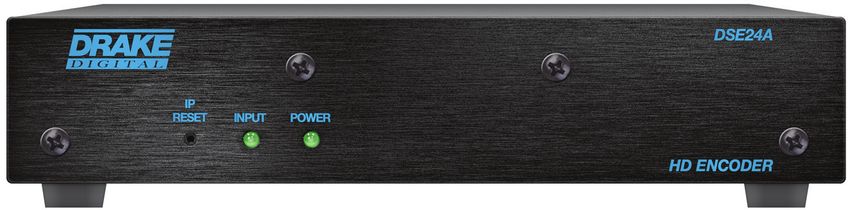
We recommend that you write the following information in the spaces provided below.

         Purchase Location Name:

         Purchase Location Telephone Number:

         DSE24A Serial Number:

This product incorporates copyright protection technology that is protected by U.S. patents and other
intellectual property rights. Reverse engineering or disassembly is prohibited.

                                     Manual Revision
The 2nd release has added cross link cable to Installation & Setup – Unpacking on page 10.

The 1st release of this manual uses firmware release version 0.9.0.0.

         For more information regarding product firmware releases, please visit our website
         at www.rldrake.com. You may also contact Technical Assistance at 937-746-6990 or
         by email: servicehelp@rldrake.com

2      937.746.4556 | www.rldrake.com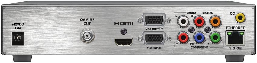
Table of Contents
GENERAL & SAFETY INFORMATION
SAFETY INSTRUCTIONS & CAUTION STATEMENTS..........................................................................................................                                                        4
GENERAL DESCRIPTION & FEATURES................................................................................................................................                                            6
SPECIFICATIONS.....................................................................................................................................................................                       7
FRONT AND REAR PANEL OPERATION...............................................................................................................................                                             8

INSTALLATION & SETUP
INSTALLATION & POWER-UP................................................................................................................................................ 10
COMMUNICATING WITH THE UNIT ...................................................................................................................................... 11

UNIT CONFIGURATION
ACCESSING THE UNIT VIA WEB BROWSER ..................................................................................................................... 12
MAIN TAB ................................................................................................................................................................................ 13
    STATUS SCREEN................................................................................................................................................................................... 13
    VIDEO SCREEN..................................................................................................................................................................................... 14
    AUDIO SCREEN..................................................................................................................................................................................... 15
    TS CONFIG SCREEN............................................................................................................................................................................. 16
    IP SCREEN............................................................................................................................................................................................. 18
    QAM SCREEN........................................................................................................................................................................................ 19
    OUTPUT SCREEN.................................................................................................................................................................................. 20
    REFRESH TAB....................................................................................................................................................................................... 21
NETWORK TAB ...................................................................................................................................................................... 21
ADMIN TAB ............................................................................................................................................................................. 22
TIME TAB ................................................................................................................................................................................ 25
EVENT LOG TAB .................................................................................................................................................................... 26

APPENDIX
A. VIEWING IP OUTPUT ON VLC MEDIA PLAYER ............................................................................................................. 27

SERVICE & WARRANTY
SERVICE................................................................................................................................................................................... 30
WARRANTY.............................................................................................................................................................................. 31

                                                                                                                                  937.746.4556 | www.rldrake.com                                           3
Important Safety Instructions
1. Read Instructions—All the safety and operating instructions should be read before the product, be sure the antenna or cable system is grounded so as to provide some protection
product is operated. against voltage surges and built-up static charges. Article 810 of the National Electrical Code,
ANSI/NFPA 70, provides information with regard to proper grounding of the mast and sup-
2. Retain Instructions—The safety and operating instructions should be retained for future porting structure, grounding of the lead-in wire to an antenna discharge unit, size of ground-
reference. ing conductors, location of antenna-discharge unit, connection to grounding electrodes, and
3. Heed Warnings—All warnings on the product and in the operating instructions should be requirements for the grounding electrode. See Figure A.
adhered to. 15. Lightning—For added protection for this product during a lightning storm, or when it
4. Follow Instructions—All operating and use instructions should be followed. is left unattended and unused for long periods of time, unplug it from the wall outlet and
disconnect the antenna or cable system. This will prevent damage to the product due to
5. Cleaning—Unplug this product from the wall outlet before cleaning. Do not use liquid lightning and power-line surges.
cleaners or aerosol cleansers. Use a damp cloth for cleaning.
16. Power Lines—An outside antenna system should not be located in the vicinity of over-
6. Attachments—Do not use attachments that are not recommended by the product manu- head power lines, other electric light or power circuits, where it can fall into such power lines
facturer as they may cause hazards. or circuits.
7. Water and Moisture—Do not use this product near water—for example, near a bathtub, 17. Overloading—Do not overload wall outlets, extension cords, or integral convenience
wash bowl, kitchen sink or laundry tub; in a wet basement; or near a swimming pool; and receptacles as this can result in a risk of fire or electric shock.
the like.
18. Object and Liquid Entry—Never push objects of any kind into this product through open-
8. Accessories—Do not place this product on an unstable cart, stand, tripod, bracket, or ings as they may touch dangerous voltage points or short-out parts that could result in a fire
table. The product may fall, causing serious injury to a child or adult, and serious damage or electric shock. Never spill liquid of any kind on the product.
to the product. Use only with a cart, stand, tripod, bracket, or table recommended by the
manufacturer, or sold with the product. Any mounting of the product should follow the 19. Servicing—Do not attempt to service this product yourself as opening or removing cov-
manufacturer’s instructions, and should use a mounting accessory recommended by the ers may expose you to dangerous voltage or other hazards. Refer all servicing to qualified
manufacturer. service personnel.
9. A product and cart combination should be moved with care. Quick stops, excessive force, 20. Damage Requiring Service—Unplug this product from the wall outlet and refer servicing
and uneven surfaces may cause the product and cart combination to overturn. to qualified service personnel under the following conditions:
10. Ventilation—Slots and openings in the cabinet are provided for ventilation and to ensure a. When the power-supply cord or plug is damaged,
reliable operation of the product and to protect it from overheating, and these openings b. If liquid has been spilled, or objects have fallen into the product,
must not be blocked or covered. The openings should never be blocked by placing the
product on a bed, sofa, rug, or similar surface. This product should not be placed in a built-in c. If the product has been exposed to rain or water,
installation such as bookcase or rack unless proper ventilation is provided or the manufac-
turer’s instructions have been adhered to. d. If the product does not operate normally by following the operating instructions. Adjust
only those controls that are covered by the operating instructions as an improper adjust-
11. Power Sources—This product should be operated only from the type of power source ment of other controls may result in damage and will often require extensive work by a
indicated on the marking label. If you are not sure of the type of power supplied to your qualified technician to restore the product to its normal operation,
home, consult your product dealer or local power company. For products intended to oper-
ate from battery power, or other sources, refer to the operating instructions. e. If the product has been dropped or damaged in any way, and
12. Grounding or Polarization—This product may be equipped with a polarized alternat- f. When the product exhibits a distinct change in performance—this indicates a need for
ingcurrent line plug (a plug having one blade wider than the other). This plug will fit into service.
the power outlet only one way. This is a safety feature. If you are unable to insert the plug 21. Replacement Parts—When replacement parts are required, be sure the service techni-
fully into the outlet, try reversing the plug. If the plug should still fail to fit, contact your cian has used replacement parts specified by the manufacturer or have the same characteris-
electrician to replace your obsolete outlet. Do not defeat the safety purpose of the polarized tics as the original part. Unauthorized substitutes may result in fire, electric shock or other
plug. Alternate Warnings—If this product is equipped with a three-wire grounding-type hazards.
plug, a plug having a third (grounding) pin, the plug will only fit into a grounding-type power
outlet. This is a safety feature. If you are unable to insert the plug into the outlet, contact 22. Safety Check—Upon completion of any service or repairs to this product, ask the service
your electrician to replace your obsolete outlet. Do not defeat the safety purpose of the technician to perform safety checks to determine that the product is in proper operating
grounding-type plug. condition.
13. Power-Cord Protection—Power-supply cords should be routed so that they are not 23. Wall or Ceiling Mounting—The product should be mounted to a wall or ceiling only as
likely to be walked on or pinched by items placed upon or against them, paying particular recommended by the manufacturer.
attention to cords at plugs, convenience receptacles, and the point where they exit from the 24. Heat—The product should be situated away from heat sources such as radiators, heat
product. registers, stoves, or other products (including amplifiers) that produce heat.
14. Outdoor Antenna Grounding—If an outside antenna or cable system is connected to the
FIGURE A
CAUTION STATEMENT Example of antenna grounding as per National Electrical Code, ANSI/NFPA 70
WARNING: TO PREVENT FIRE OR
ELECTRICAL SHOCK DO NOT ANTENNA
LEAD IN
EXPOSE TO RAIN OR MOISTURE WIRE
! CAUTION ! GROUND CLAMP
RISK OF ELECTRIC SHOCK ANTENNA
DO NOT OPEN DISCHARGE UNIT
(NEC SECTION 810-20)
WARNING: TO REDUCE THE RISK OF ELECTRIC SHOCK, DO NOT
REMOVE POWER SUPPLY COVERS
NO USER-SERVICEABLE PARTS INSIDE ELECTRIC GROUNDING
REFER SERVICING TO QUALIFIED PERSONNEL
SERVICE CONDUCTORS
EQUIPMENT (NEC SECTION 810-21)
An appliance and cart combination should be moved with care. Quick stops, excessive
GROUND CLAMPS
force and uneven surfaces may cause the appliance and cart combination to overturn.
POWER SERVICE GROUNDING ELECTRODE
SYSTEM (NEC ART 250, PART H)
The lightning flash with arrow head symbol, within an equilateral triangle, is intended to
alert the user to the presence of uninsulated “dangerous voltage” within the product’s
NEC - NATIONAL ELECTRIC CODE
enclosure that may be of sufficient magnitude to constitute a risk of electric shock to
persons.
The exclamation point within an equilateral triangle is intended to alert the user to
the presence of important operating and maintenance (servicing) instructions in the
NOTE TO CATV SYSTEM INSTALLERS:
literature accompanying the appliance.
THIS REMINDER IS PROVIDED TO CALL THE CATV
SYSTEM INSTALLER’S ATTENTION TO ARTICLE 820 - 40
WARNING: TO REDUCE THE RISK OF FIRE OR ELECTRIC SHOCK, DO NOT EXPOSE THIS
OF THE NEC WHICH PROVIDES GUIDELINES FOR PROPER
APPLIANCE TO RAIN OR MOISTURE. DO NOT OPEN THE CABINET, REFER
SERVICING TO QUALIFIED PERSONNEL ONLY.
GROUNDING AND, IN PARTICULAR, SPECIFIES THAT
CAUTION: TO PREVENT ELECTRIC SHOCK, DO NOT USE THIS (POLARIZED) PLUG WITH AN THE CABLE GROUND SHALL BE CONNECTED TO THE
EXTENSION CORD RECEPTACLE OR OTHER OUTLET UNLESS THE BLADES CAN
BE FULLY INSERTED TO PREVENT BLADE EXPOSURE. GROUNDING SYSTEM OF THE BUILDING, AS CLOSE TO
THE POINT OF CABLE ENTRY AS PRACTICAL.
4 937.746.4556 | www.rldrake.comImportantes De Sécurité
1. Lire les directives—Toutes les directives de sécurité et d’utilisation devraient être lues aux électrodes de mise à la terre et les spécifications pour les électrodes de mise à la terre.
avant de mettre l’appareil en opération.
Voir la figure A.
2. Conserver les directives—Les directives de sécurité et d’utilisation devraient être con-
servées pour consultation future. 15. Foudre—Pour une protection supplémentaire de cet appareil pendant un orage élec-
trique, ou quand il est laissé sans surveillance et inutilisé pendant de longues périodes, le
3. Tenir compte des avertissements—Tous les avertissements apparaissant sur l’appareil et débrancher de la prise électrique murale et déconnecter le système d’antenne ou de câble.
dans les consignes d’utilisation devraient être respectés. Ceci préviendra les dommages à l’appareil dus à la foudre et aux surtensions.
4. Suivre les directives—Toutes les directives d’opération et d’utilisation devraient être 16. Lignes électriques—Un système d’antenne extérieur ne devrait pas être situé à proximité
suivies. de lignes électriques aériennes ou de tout autre circuit électrique, où il pourrait tomber sur
de tels circuits ou lignes électriques. Lors de l’installation d’un système d’antenne extérieur,
5. Nettoyage—Débrancher l’appareil de la prise électrique murale avant le nettoyage. Ne pas d’extrêmes précautions devraient être prises afin de prévenir tout contact avec des lignes ou
utiliser de nettoyants liquides ou aérosols. Employer un linge humide pour le nettoyage. circuits électriques. Entrer en contact avec de tels circuits ou lignes électriques pourrait être
6. Fixation—Ne pas utiliser d’autres fixations que celles recommandées par le manufacturier; fatal.
elles pourraient être source de dangers. 17. Surcharge—Ne pas surcharger les prises de courant murales, les rallonges électriques ou
7. Eau et humidité—Ne pas utiliser cet appareil près de l’eau. Par exemple, près d’une les prises de courant intégrées. Un risque d’incendie ou de choc électrique pourrait résulter
baignoire, d’un bac de lavage, d’un évier de cuisine ou d’une cuvette de lessivage; dans un d’une telle surcharge.
sous-sol humide; ou à proximité d’une piscine; et autres environnements similaires. 18. Insertion d’objet ou de liquide—Ne jamais insérer d’objet par les ouvertures de cet
8. Accessoires—Ne pas installer cet appareil sur un chariot, un socle, un trépied, un support appareil. Il pourrait toucher des points de voltage dangereux ou court-circuiter des pièces,
ou une table instables. L’appareil pourrait tomber, entraînant des blessures graves à un ce qui pourrait résulter en incendie ou en choc électrique. Ne jamais verser de liquide sur
enfant ou à un adulte, et des dommages importants à l’appareil. Employer seulement avec l’appareil.
un chariot, un socle, un trépied, un support, ou une table recommandés par le fabricant ou 19. Entretien—Ne pas essayer de faire soi-même l’entretien de cet appareil. En ouvrir ou en
vendu avec l’appareil. Toute installation de l’appareil devrait être conforme aux directives du retirer les couvercles pourrait vous exposer à des voltages dangereux ou à d’autres dangers.
manufacturier et devrait utiliser des accessoires d’installation recommandés par celui-ci. Confier tout entretien à un personnel de service qualifié.
9. Un chariot supportant l’appareil devrait être déplacé avec précaution. Les arrêts brusques, 20. Dommage exigeant un entretien—Débrancher cet appareil de la prise de courant élec-
la force excessive et les surfaces inégales peuvent renverser le chariot. trique et confier l’entretien au personnel de service qualifié dans les éventualités suivantes:
10. Ventilation—Des fentes et ouvertures dans le châssis sont prévues pour la ventilation a. Quand le cordon d’alimentation ou sa fiche sont endommagés,
de l’appareil, pour en assurer la fiabilité d’opération et le protéger contre la surchauffe.
Ces ouvertures ne doivent pas être bloquées ou recouvertes. Ces ouvertures ne devraient b. Si des objets sont tombés dans l’appareil, ou si du liquide y a été renversé,
jamais être bloquées en plaçant l’appareil sur un lit, un sofa, une couverture, ou une surface
semblable. Cet appareil ne devrait pas être installé dans un meuble encastré comme une bib- c. Si l’appareil a été exposé à la pluie ou à l’eau,
liothèque ou une étagère à moins de lui fournir une ventilation adéquate ou que l’installation d. Si l’appareil ne fonctionne pas normalement en suivant les consignes d’utilisation.
soit conforme aux directives du manufacturier. Ajuster seulement les commandes qui sont mentionnées dans le guide d’opération. Un
11. Sources d’alimentation électrique—Cet appareil devrait être utilisé seulement avec mauvais ajustement des autres commandes pourrait causer des dommages à l’appareil et
le type d’alimentation électrique inscrite sur l’étiquette. Si vous n’êtes pas certain du type souvent exiger un travail supplémentaire de la part d’un technicien qualifié pour remettre
d’alimentation électrique fourni à votre maison, consultez le vendeur de l’appareil ou l’appareil en état normal d’opération.
l’entreprises d’énergie locale. Pour des appareils alimentés par une batterie ou d’autres e. Si l’appareil a été échappé ou endommagé de n’importe quelle façon, et
sources, se référer aux consignes d’utilisation.
f. Quand l’appareil montre un changement notable de performance – ceci indique qu’un
12. Mise à la terre ou Polarisation—Cet appareil est équipé avec un cordon d’alimentation entretien est nécessaire.
à trois fils. Il est a brancher sur une prise ayant un connecteur a la terre. Assurez-vous que la
connection a la terre ne manque pas. 21. Pièces de rechange—Si des pièces de rechange sont nécessaires, s’assurer que le tech-
nicien de service a employé des pièces de rechange spécifiques du manufacturier ou ayant
13. Protection du cordon d’alimentation—Les cordons d’alimentation devraient être dispo- les mêmes caractéristiques que les pièces originales. L’utilisation de pièces de rechange non
sés de façon à ce qu’on ne puisse marcher dessus ou qu’ils soient susceptibles d’être coincés autorisées pourrait résulter en incendie, choc électrique ou autres dangers.
par des articles placés sur ou contre eux. Une attention particulière doit être portée aux
fiches, prises de courant, et aux points où ils sortent de l’appareil. 22. Vérification de sécurité—À la suite de toute réparation ou entretien de cet appareil,
demander au technicien de service d’exécuter des vérifications de sécurité afin de s’assurer
14. Mise à la terre de l’antenne extérieure—Si un système extérieur d’antenne ou de câble que l’appareil est en condition normale de fonctionnement.
est relié à l’appareil, s’assurer que le système d’antenne ou de câble est muni d’une mise à la
terre afin de fournir une certaine protection contre les surtensions et les charges d’électricité 23. Montage au mur ou au plafond—L’appareil ne devrait être monté au mur ou au plafond
statique. L’article 810 du code électrique national, ANSI/NFPA 70, fournit l’information néces- qu’uniquement de la façon recommandée par le manufacturier.
saire en ce qui concerne la mise à la terre appropriée du mât et de la structure porteuse, 24. Chaleur—L’appareil devrait être situé loin de sources de chaleur telles que des radia-
la mise à la terre du câble de connexion à une unité de décharge d’antenne, le calibre des teurs, des registres de chaleur, des fourneaux, ou d’autres appareils (y compris amplifica-
conducteurs de mise à la terre, la location de l’unité de décharge d’antenne, le raccordement teurs) produisant de la chaleur.
FIGURE A
ATTENTION DÉCLARATION Exemple de mise à la terre d’antenne selon le Code Électrique National, ANSI/NFPA 70
AVERTISSEMENT: AFIN D’ÉVITER TOUT RISQUE D’INCENDIE
ANTENNA
OU D’ÉLECTROCUTION, NE PAS EXPOSER CET APPAREIL À LA LEAD IN
WIRE
PLUIE OU À L’HUMIDITÉ.
ATTACHES DE
MISE À LA TERRE
! AVERTISSEMENT ! UNITÉ DE DÉCHARCHE D’ANTENNE
RISQUE DE CHOC ELECTRIQUE - (NEC SECTION 810-20)
NE PAS OUVRIR
ATTENTION: POUR RÉDUIRE LE RISQUE D’ÉLECTROCUTION, NE PAS APPAREILS
ENLEVER LE DOS DE L’APPAREIL NI OUVRIR LE BOÎTIER. AUCUNE PIÈCE N’EST
RÉPARABLE PAR L’UTILISATEUR À L’INTÉRIEUR. SE RÉFÉRER UNIQUEMENT À ÉLECTRIQUES CONDUCTEURS DE MISE À LA TERRE
DES TECHNICIENS QUALIFIÉS POUR L’ENTRETIEN. DE SERVICE (NEC SECTION 810-21)
ATTACHES DE
Une combinaison de l’appareil et chariot doit être déplacé avec précaution. Des arrêts MISE À LA TERRE
brusques, une force excessive et des surfaces inégales peuvent causer la combinaison SYSTÈME DE MISE À LA TERRE DU BÂTIMENT
de l’appareil et le chariot. (NEC ART 250, PART H)
NEC - CODE ÉLECTRIQUE NATIONAL
Le symbole de l’éclair à l’intérieur d’un triangle équilatéral est destiné à alerter
l’utilisateur sur la présence d’une “tension dangereuse” non isolée dans le boîtier du
produit. cette tension est suffisante pour provoquer l’électrocution de personnes.
Le point d’exclamation à l’intérieur d’un triangle équilatéral est destiné à alerter
l’utilisateur sur la présence d’opérations d’entretien importantes au sujet desquelles des
renseignements se trouvent dans le manuel d’instructions.
NOTE AUX INSTALLATEURS DE SYSTÈME DE CATV:
CE RAPPEL EST FOURNI POUR PORTER À L’ATTENTION DES
AVERTISSEMENT: AFIN D’ÉVITER TOUT RISQUE D’INCENDIE OU D’ÉLECTROCUTION, NE PAS INSTALLATEURS DE SYSTÈME DE CATV, L’ARTICLE 820 - 40 DU
EXPOSER CET APPAREIL À LA PLUIE OU À L’HUMIDITÉ. NE PAS OUVRIR LE
BOÎTIER, CONFIER TOUS TRAVAUX À DU PERSONNEL TECHNIQUE QUALIFIÉ. NEC QUI DONNE DES DIRECTIVES POUR UNE MISE À LA TERRE
APPROPRIÉE ET, EN PARTICULIER, SPÉCIFIE QUE LE CÂBLE DE
CAUTION: POUR PREVENIR LES CHOCS ELECTRIQUES, NE PAS UTILISER CETTE FICHE MISE À LA TERRE DEVRAIT ÊTRE RACCORDÉ AU SYSTÈME DE
POLARISEE AVEC UN PROLONGATEUR, UNE PRISE DE COURANT OU UNE MISE À LA TERRE DU BÂTIMENT LE PLUS PRÈS POSSIBLE DE
AUTRE SORTIE DE COURANT, SAUF SI LES LAMES PEUVENT ETRE INSEREES A L’ENTRÉE DU CÂBLE.
FOND SANS EN LAISSER AUCUNE PARTIE A DECOUVERT.
937.746.4556 | www.rldrake.com 5General Description & Features INTRODUCTION The DSE24A is a single channel HD encoder with RF QAM and IP outputs. Drake’s DSE24A encodes an uncompressed video source from devices with HDMI, high-resolution component, composite or VGA outputs. The DSE24A encodes the incoming video to MPEG2. It is then internally connected to a QAM modulator and low-noise upconverter. The DSE24A comes as a small, modular desktop model but can be rack-mounted in just 1RU of height by using the optional 19” rack mounting panel. Control and access is through a GUI-based menu via Web browser. Distribution is over legacy coaxial networks. This provides instant access to an extensive network of digital displays capable of viewing valuable ad-based or informational video in a vibrant high-definition format. FEATURES • Receives High-Resolution Component, Composite, VGA, or HDMI (non-HDCP content-protection) from one video source • QAM and IP Outputs • Digitally Encodes to MPEG2 • Encodes to resolutions of 480i, 720p, or 1080i • Audio Encoding to Dolby® Digital • Supports Closed Captioning • GUI-based Remote Network Control and Monitoring • Desktop Model 6 937.746.4556 | www.rldrake.com
Specifications
DSE24A Digital Signage MPEG-2 Encoder with QAM Output Item # 1002571A
INPUT OUTPUT
Component RF QAM
Connector(s): 3x RCA for Video (Y, Pb, Pr) Connector(s): 1x “F” Female (Rear-panel)
Video Resolution: 480i, 720p, & 1080i Modulation: QAM 16, 32, 64, 128, and 256
Video Aspect Ratio: 4:3 & 16:9 Standards: ITU-T J.83; Annex A and B
Audio: 2x RCA for Analog Audio (L, R) Frequency Range: 5 to 1002 MHz
1x RCA for Digital Audio (PCM)
Tuning: CATV Channel Selectable (T7 to T14, 2 to 158)
HDMI Channel Bandwidth: 6 MHz
Connector(s): 1x HDMI
RF Level: +40 dBmV ±1 dB
Video Resolution: 480i, 720p, & 1080i
RF Level Adjustment: +35 to +42 dBmV, 0.5 dB increment
HDCP Encryption: Not Supported
Frequency Stability: ± 5 kHz over 32 to 122 °F (0 to 50 °C)
Audio: Embedded PCM & pass-thru Dolby® Digital only
Frequency Tolerance: ± 0.5 kHz @ 77 °F (25 °C)
VGA Phase Noise: -98 dBc (@ 10 kHz)
Connector(s): 2x Female VGA (Input + Loop-through Output) Spurious: -60 dBc
Video Resolution: 640x480 @ 60 fps Broadband Noise: -70 dBc (@ +40 dBmV output level, 5.5 MHz
800x600 @ 60 fps bandwidth)
1024x768 @ 60 fps
Impedance: 75 Ω
Audio: 2x RCA for Analog Audio (L, R)
1x RCA for Digital Audio (PCM) Return Loss: 14 dB typical
Composite Signal-to-Noise Ratio (SNR): 40 dB typical
Connector(s): 1x RCA for Video (Y) MER: 40 dB typical
Video Resolution: 480i I/Q Phase Error: Less than 1 degree
Audio: 2x RCA for Analog Audio (L, R) I/Q Amplitude Imbalance: Less than 1%
1x RCA for Digital Audio (PCM)
IP
ENCODING PROFILE Connector(s): 1x RJ45 (Rear-panel)
Video Standard: 100/1000Base-T Ethernet
Output Format: MPEG-2 HD MP@ML; ISO 13818-2 UDP/RTP: Supported (user-selectable)
Chroma: 4:2:0 GENERAL
Resolution: 480i, 720p, & 1080i
Mechanical
Frame Rate: 29.97 fps (480i); 29.97 fps (1080i); 59.97 fps (720p)
Dimensions (W x D x H): 8.66 x 9.15 x 1.96 inches
Aspect Ratio: 4:3 & 16:9 (219.9 x 232.41 x 49.784 mm)
GOP Structure: I & P frames (user selectable) Weight: 2 lbs (0.907 kg)
Transport Rate: Variable (user selectable) Operating Temperature: 32 to 122 °F (0 to 50 °C)
Video Bit Rate: Variable (user selectable) Storage Temperature: -13 to 158 °F (-25 to 70 °C)
Video Pre-filter: Variable (user selectable) Operating Humidity: 0 to 95% RH @ 35 °C max, non-condensing
Color Space: YCbCr and RGB Storage Humidity: 0 to 95% RH @ 35 °C max, non-condensing
Audio Power
Output Format: Dolby® Digital Power: External Power Supply
(Input 115-230VAC / Output 12VDC @ 3 Amp)
Sampling Rate: 48 kHz
Dissipation: 16 W
Bit Rate: Variable; 96 - 448 Kbps
Closed Captioning ALARMS/MONITORING/CONTROL
Component: EIA- 608; 1x RCA (CC) Local Monitoring: 1x Power LED
1x Status LED
HDMI: EIA- 608; 1x RCA (CC)
Local Control: 1x IP Reset Button
VGA: EIA- 608; 1x RCA (CC)
Remote Monitoring/ GUI-based menu via Web browser
Composite: EIA- 608 Control: (1x RJ45 (rear-panel); 100/1000Base-T, also used for IP
output)
Specifications are subject to change without notice or obligation.
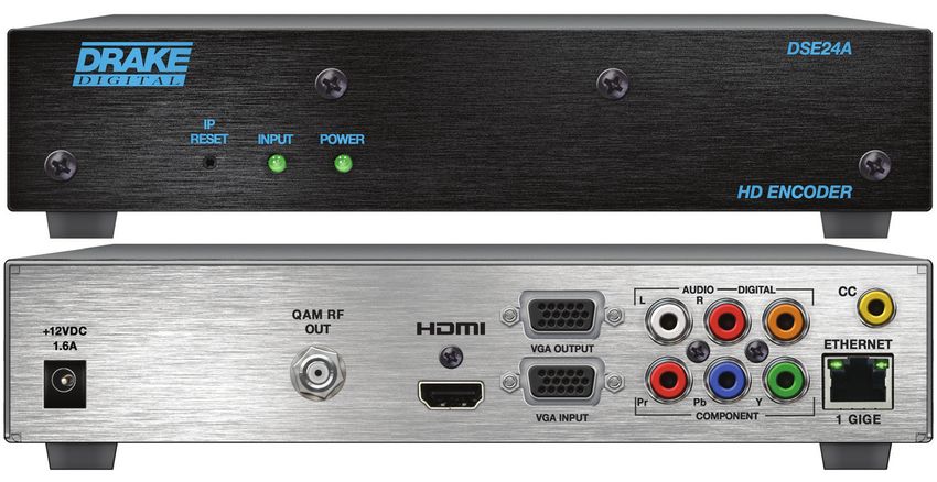
937.746.4556 | www.rldrake.com 7Front and Rear Panel Operation
FRONT PANEL VIEW:
1 2 3
FRONT PANEL DESCRIPTION
1 IP Reset: When pressed for >10 seconds, the IP address of the control port will be enabled to the default factory
IP address (172.16.70.1, Subnet Mask 255.255.0.0). The login credentials will also be enabled to the default
username Admin and password pass, which are both case-sensitive.
Note: The old IP address, login, and password will still be present in the encoder settings. To clear the reset mode simply
reboot the encoder.
2 Status LED: indicates the status of input video and audio as follows:
Green = Both Video and Digital Audio inputs are present.
Red = Either the Video or Digital Audio is not present, or internal temperature is too high.
Note: The encoder does not sense analog audio inputs. Therefore, if the Audio is set for Analog, the status indicator will
only be valid for video.
3 Power LED: indicates if the unit is receiving power.
Green = power is detected.
Off = indicates (i) power is not connected, or (ii) power is connected but the power supply or encoder is
defective. The unit must be sent to the factory for repair for condition (ii).
8 937.746.4556 | www.rldrake.comFront and Rear Panel Operation
REAR PANEL VIEW:
7 9
11
4 12
5 6 8 10
REAR PANEL DESCRIPTION
4 +12VDC, 1.6A: ITE power supply - rated 115-230VAC / Output 12VDC @ 3 Amp.
5 QAM RF Output: "F" Connector for QAM Output.
6 HDMI: HDMI connector for unencrypted HDMI input.
The DSE24A does not accept HDCP-Encrypted HDMI Input.
7 VGA Output: DE-15 female connector for loop-through VGA output.
8 VGA Input: DE-15 female connector for VGA input.
9 Audio: RCA connectors (marked: L and R) for Analog Left/Right Audio input and RCA connector (marked: DIGITAL)
for Digital Audio program input.
10 Component Out: RCA connectors (marked: Pr, Pb, Y) for Analog Component Video input. The RCA connector
(marked: Y) is also used for Composite Video input.
11 CC: RCA connector (marked “CC”) for Analog NTSC Closed Captioning (EIA-608, also known as Line 21), which
will then be digitized and inserted in the MPEG-2 Transport Stream of the Component, HDMI, and VGA inputs.
12 ETHERNET 1 GIGE: RJ45 connector for 100/1000Base-T Ethernet interface for monitoring and configuring the
unit. The same interface is used to deliver the IP output. Only static IP address can be assigned to this interface.
(Factory Default: "172.16.70.1")
937.746.4556 | www.rldrake.com 9Installation & Setup
Unpacking
You will find the following items in the box:
• DSE24A Encoder (QTY=1)
• Switching Mode Power Supply, 12 VDC, 3.0A (Item: 515132200)
• Cross Link Cable, 7 Ft (Item: 515102875 A)
Installation
The DSE24A encoder is designed for a desk/table top installation. An optional rack panel (stk#1002565A) allows two encoders to be
mounted in a 1RU.
You can mount the chassis in a standard EIA, 24 inch (610 mm) deep, enclosed rack. Secure the rack chassis front panel to the rack by
inserting four machine screws, with cup washers, through the four mounting holes in the front panel.
When installing units in a headend rack, it is recommended to leave a 1 rack unit space (1.75” high) between units to maximize air flow.
Power-Up
To power up the unit, connect the line cord of the external supply to a 115/230 VAC outlet.
The “POWER” LED on the front-panel will light green.
10 937.746.4556 | www.rldrake.comInstallation & Setup
To begin setup, connect the appropriate input and output video cables and plug in the DSE24A power cable.
ETHERNET ACCESS:
Local or remote communication with the unit is only possible through a GUI-based menu via any standard web browser.
Chrome, Firefox and Internet Explorer 7 (or higher) are recommended. Before you can communicate with the unit you
must configure your computer's IP address to conform with your existing IP network or LAN. To do so, follow these steps:
Plug one end of an Ethernet cross cable to the unit’s front-panel RJ45 interface marked “ETHERNET 1 GIGE”. Plug the
other end of the cable to your computer.
1. The following steps explain how to do this for a computer with Windows 7, Windows 8.x or Windows 10 operating
software:
a) On your computer, navigate to the "Network and Sharing Center".
(Note: This can be found using the search box in the Start Menu or for Windows 8.x, the Start Screen)
b) Once open, click on “Change Adapter Settings” on left hand side of the window.
c) Right-click on the "Local Area Connection", and then click on the "Properties".
d) A dialog box entitled "Local Area Connection Properties" will appear. In this box, double-click on the
"Internet Protocol Version 4 (TCP/IPv4)".
e) A dialog box entitled "Internet Protocol Version 4 (TCP/IPv4) Properties" will appear. Select the
"Use the following IP address" option and enter the following addresses:
IP address: 172.16.70.2
Subnet mask: 255.255.255.0
No need to enter a value for the Default Gateway for local access.
Click OK to close the dialog box. Now your computer is ready to communicate with the unit.
- OR -
2. The following steps explain how to do this for a computer with Windows XP operating software:
a) On your computer, open the "Control Panel"
b) Double-click on "Network Connections"
c) Right-click on the "Local Area Connection", and then click on the "properties".
dialog box entitled "Local Area Connection Properties" will appear. In this box, double-click on the "Internet
d) A
Protocol (TCP/IP)".
dialog box entitled "Internet Protocol (TCP/IP) Properties" will appear. Select the "Use the following IP address"
e) A
option and enter the following addresses:
IP address: 172.16.70.2
Subnet mask: 255.255.255.0
No need to enter a value for the Default Gateway for local access.
Click OK to close the dialog box. Now your computer is ready to communicate with the unit.
937.746.4556 | www.rldrake.com 11Unit Configuration
Accessing the Unit via the Web Browser
The user must complete the steps described in "Installation & Setup" before proceeding as follows:
1. Open a web browser on your computer (Chrome, Firefox, and IE7+ are recommended) and enter the following URL
address (http://172.16.70.1). The "Login" Screen (Figure 1) will appear.
Figure 1 - Login Screen
2. Enter the following case-sensitive factory-default Username and Password, and click on the "Submit" button.
NOTE: When logged in as Admin, the user has read and write permission. Only one Admin can be logged
in at a time. When logged in as Guest, the user has read permission only. Up to four Guests can be logged
in simultaneously.
Username = Admin (case-sensitive)
Password = pass (case-sensitive)
- OR -
Username = Guest (case-sensitive)
Password = pass (case-sensitive)
Monitoring and configuration of the unit is achieved via a series of web pages described in following sections. The following
read-only information is displayed in a white “page header”on top of each web page:
ESN: unit’s Serial number
Headend name: a user-defined field to make identification easier
Temperature: temperature of unit’s chipset
Uptime: time elapsed since last time the unit was turned on
Location: a user-defined field to make identification easier
As shown in Figure 2, under the white “page header” the following Primary tabs will appear:
• Primary tab “Main” (includes sub-tabs: Status, Video, Audio, TS Config, IP, QAM, Output and Refresh.)
• Primary tab “Network” (no sub-tabs)
• Primary tab “Time” (no sub-tabs)
• Primary tab “Event Log” (no sub-tabs)
• Primary tab "Logout" (no sub-tabs, used to log out of the unit)
• Primary tab “Admin” (no sub-tabs)
Each Primary and sub-tab is described in the subsequent Sections
12 937.746.4556 | www.rldrake.comUnit Configuration
Main Tab: Status Screen
The “Main Tab: Status" sub-tab (Figure 2) is a “read only” screen and displays the following information:
1 2 3 4
Figure 2 - Main Tab: Status Screen
In the section entitled "TS" under the orange header, the following parameters about the output are displayed:
1 TS: indicates the selected program's information. The program information includes the PMT PID, Program number,
Short Name, Major-minor channel number, Video elementary stream PID, Video input source, Audio elementary
stream PID, and Audio input source.
2 Bitrates: indicates the transport stream bitrate (see 2 of "Main Tab: Video" section) and the TS Bitrate (see 2 of
"Main Tab: TS Config" section).
In the section entitled "Output" under the blue header, the following parameters about the output are displayed:
3 IP: indicates the encapsulation method, IP address, and the port number to which an output is assigned.
4 QAM: indicates the RF channel number of the QAM output.
937.746.4556 | www.rldrake.com 13Unit Configuration
Main Tab: Video Screen
The “Main Tab: Video” sub-tab (Figure 3) is a “user-configurable” screen to select the video encoder parameters for the
input program.
1
2
3
4
5
6
7
8
Figure 3 - Main Tab: Video Screen
1 Source: allows the user to select the type of video input source. Options are: Composite, Component, VGA, and HDMI.
2 Bitrate: user must enter the bitrate for the input video. It is recommended that the bitrate of the input video does not
exceed “TS Bitrate” selected on the “Main Tab: TS Config” screen (see 2 of "Main Tab: TS Config" section).
3 Closed Caption: the process of passing the EIA-608 Closed Captioning (CC) information and displaying the CC text
on television or other visual display. Options: Enabled and Disabled. (Factory Default: “Disabled”)
4 Video Filter Level: a two-dimensional low-pass filter controlling the degree of which the input video is filtered.
Options are: Off (no filtering), On-Level 1, On-Level 2, On-Level 3, and On-Level 4 (highest filtering
coefficient). Level 1 filtering of the video will smoothen the sharp edges of the pixels and produce a softer
image. The softer an image, the less number of bits required to encode the image at the quantizer level.
5 Video Coding Mode: user must select the Video Coding Mode. Options: Frame and Field. (Factory Default: "Frame")
6 HDMI Colorspace: allows the user to select the color space of HDMI input source. Options: RGB and YCbCr.
(Factory Default: "RGB")
NOTE: If the displayed pictures are very green or violet in color, it is a good indication that
this setting is incorrect.
Option 6 will be available only if "HDMI" is selected in 1 above.
7 GOP Size: the length between I-frames is known as the group of pictures (GOP) size. The range is 1 to 120 with 1
I-frame for every 14 non-I-frames. (Factory Default: "15")
8 Test Pattern: the video pattern that will be inserted into the transport stream if no input video is detected. Options:
Color Bars, Black Screen, Blue Screen, and Red Screen.
Remember to click on the SAVE button to apply the new values/configurations.
14 937.746.4556 | www.rldrake.comUnit Configuration
Main Tab: Audio Screen
The “Main Tab: Audio” sub-tab (Figure 4) is a “user-configurable” screen where the following parameters associated with
the Dolby® Digital encoded stereo audio are configured and displayed for the audio input under a green header:
1
2
3
4
5
6
7
8
9
Figure 4 - Main Tab: Audio Screen
1 Source: allows the user to select the type of audio input source. Options: Analog, Digital, and HDMI.
2 Data Rate: allows the user to select the audio encoding bitrate in kbps (kilobits per second). The range is 96 to 448
kbps. (Factory Default: 192 kbps, which supports Audio Coding Mode 2/0:L, R)
3 Delay: allows the user to adjust the audio delay (-300 to 300 ms) to correct for input video/audio sync mismatch.
4 Sample Rate: indicates the input sampling rate of the encoder. The unit supports 48 kHz sampling rate.
5 Audio Coding Mode: also referred to as Channel mode. Indicates the number of main audio channels within the
encoded bitstream and also indicates the channel format. The unit supports 2/0:L,R = audio is a dual channel (Left &
Right).
6 Dialog Normalization: behaves as an audio Automatic Gain Control (AGC) or Dynamic Range Control (DRC). It has
the ability to take different incoming audio levels and normalize them. The ability of the Dialog Normalization depends
on the configuration of the Dynamic Range Control. The unit allows you to adjust the normalization from -1 to -31 dB.
The typical value is -27 dB. This is based on the standard film audio formats which normally are between -25 and
-31 dB.
7 Dolby Surround Mode: indicates if the audio is two-channel Dolby or not. Options:
Unspecified: indicates the decoder must determine the audio format by itself.
Disabled: indicates the audio is not encoded in surround mode.
Enabled: indicates the audio is encoded in surround mode.
8 Line Mode: allows the user to select the type of Dynamic Range Compression to be applied to signals that will be used
as direct audio feeds into a TV tuner or other receive devices. (Factory Default: “None”)
937.746.4556 | www.rldrake.com 15Unit Configuration
Main Tab: Audio Screen (continued)
9 RF Mode: allows the user to select the type of Dynamic Range Compression to be applied to signals that will be used
for retransmission on an RF carrier, and fed into a TV tuner or other receive device(s). (Factory Default: “None”)
Options for 8 and 9 are:
i) None: no dynamic range controls have been assigned.
ii) Film Standard: suitable for movies where the very low-level sounds are not to be amplified due to other undesirable
background noises that may become audible, but rather the peaks and valleys are normalized instead. It has a null
bandwidth of 10 dB (-31 to -21 dB) and can add up to 6 dB of boost for low levels and attenuate high levels.
iii) Film Light: is similar to “Film Standard” but with a null bandwidth of 20 dB (-41 to -21 dB) and can add up to 6 dB of boost
for low levels and attenuate high levels.
iv) Music Standard: suitable for program content that is mainly made up of music where the sound level is to be normalized
(reducing the loudness) to be consistent with other programs. It has a null bandwidth of 10 dB (-31 to-21 dB) and can add up
to 12 dB of boost for low levels and attenuate high levels.
v) Music Light: similar to “Music Standard” but with a null bandwidth of 20 dB (-41 to -21 dB) and can add up to 12 dB of
boost for low levels and attenuate high levels.
vi) Speech: suitable for program content that is mainly made up of speech only and has a null band width of 10 dB (-31 to
-21 dB) for average speech and can add up to 15 dB of boost for low levels and attenuate high levels.
Remember to click on the SAVE button to apply the new values/configurations.
Main Tab: TS Configuration Screen
The "Main Tab: TS Config” sub-tab (Figure 5) is a “read and write” screen to assign the TS parameters.
1 2 3 4
5 6 7 8 9 10
Figure 5 - Main Tab: TS Config Screen
In the section entitled “TS Output Configuration”, the user can select and configure the following parameters of the output
TS:
1 TS ID: user must enter the identification number for the Transport Stream (TS) output. The range is 1 to 65535.
2 TS Bitrate: user must select the bitrate for the output TS. Options are 19.39 Mbps and 38.81 Mbps.
16 937.746.4556 | www.rldrake.comUnit Configuration
Main Tab: TS Configuration Screen (continued)
Always select the option "QAM Modulator", if QAM output is required. The TS Bitrate assigned will
then depend on the "Output QAM Mode" selected on the "Main Tab: QAM" Screen
(refer to 5 in "Main Tab: QAM" section) and will be as follows:
QAM Output Mode TS Bitrate assigned (Mbps)
64B 26.97
256B 38.81
16A 18.64
32A 23.30
64A 27.96
128A 32.62
256A 37.28
3 Modulation Mode: allows the user to select the modulation mode. Options are: Reserved, Analog, QAM64,
QAM256, 8-VSB, and 16-VSB.
4 Out of Band: An out-of-band (OOB) is a channel which is the combination of the forward and reverse OOB
channels. When a cable virtual channel is flagged as being out-of-band, it is carried on the out-of-band channel.
Options are Enable and Disable. When Enabled, assigns the OOB bit in the TS packet and labels the TS as out-of-
band.
NOTE: As per the ATSC and Cable standards, the Modulation Mode and Out-of-Band fields are
required to be assigned in the TS packet. Selecting the above two fields would allow the TS packets to
be compliant with industry standards, but would not affect the input or output configuration of the unit.
In the section entitled “Output Mapping”, the user can select and configure the following parameters for the output
TS indicated by “TS - QAM” under gray header:
5 Input: indicates the program selected by the user. It includes the Input video source, and audio source.
6 PID: user must enter the PID value for each stream. PID (Packet Identifier) values are embedded by the content
provider in the MPEG-2 stream to identify tables and programming packets.
The PID value must be unique in an output stream. If a duplicate PID exists, assign a different PID
in the range of 48 to 8176 (recommended range provided by the International Standards)
7 Program Number: user must enter an output program number. The PMT (Program Map Table) provides
information for program present in the transport stream such as program_number, and the list of the elementary
streams (audio, video or data). The range is 1 to 65535.
8 Short Name: user must enter the short name of the channel. Up to 7 alphanumeric characters are allowed.
9 Major Channel: user must enter the major channel number for the output program. The range is 1 to 99 for
Terrestrial and 1 to 999 for Cable.
10 Minor Channel: user may enter minor channel number for the output program. The range is 1 to 99 for Terrestrial
and 0 to 999 for cable. NOTE: When zero (0) is entered as a minor channel, it sets the encoder to provide a one
part virtual channel number as entered in the major channel field. For example, a major channel of “205” with a
minor channel of “0” will be displayed as “205” on a TV. A major channel of “205” with a minor channel of “1” will
be displayed on a TV as “205-1”.
Remember to click on the SAVE button to apply the new values/configurations.
937.746.4556 | www.rldrake.com 17Unit Configuration
Main Tab: IP Screen
The “Main Tab: IP" sub-tab (Figure 6) is a “read and write” screen to assign IP parameters for the TS:
1 2 3 4 5 6
Figure 6 - “Main Tab” IP Screen
1 Destination IP: allows user to assign the IP address of the equipment to which the IP output is streamed to.
(Factory Default: "192.168.253.2")
The Destination IP Address must be present before streaming occurs, otherwise the session
is aborted. For Multicast applications, the IP address must be in the range of 244.0.0.0 through
239.255.255.255. For Unicast applications, the IP address must be outside the above-mentioned range.
2 Encapsulation: user must select the protocol that matches the protocol used by the receiving equipment.
Options are RTP and UDP. (Factory Default: "UDP")
3 Destination Port: user must enter the IP Port of the receiving equipment. The range is 1 to 65535. (Factory
Default: "50000")
4 Source Port: user must enter the IP Port of the equipment that the input IP source is streamed from. The range
is 1 to 65535. (Factory Default: "50000")
NOTE: Port number is recommended to be from 49152 to 65535. Reason: Port 1-1023 and
1024-49151 are the Reserved Ports and the Registered Ports, respectively.
5 Time to Live: is an upper limit on the time that an IP packet can exist in an IP network. The value is set by the
sender of the packet, and reduced by every host on the route to packet’s final destination. If the Time to Live
reaches zero before the packet arrives at its final destination, then the packet is discarded. The purpose of this
field is to avoid an undeliverable packet from circulating on an IP network perpetually. The range is 1 to 255.
(Factory Default: "128")
6 Stuffing: Null packets are inserted to ensure that the TS bitrate assigned in 2 of the "Main Tab: TS Config"
section remains constant. Options are Enable and Disable. It is advisable to Disable stuffing when only IP output
is used to help reduce the traffic on the network.
Remember to click on the SAVE button to apply the new values/configurations.
18 937.746.4556 | www.rldrake.comUnit Configuration
Main Tab: QAM Screen
The “Main Tab: QAM" sub-tab (Figure 7) is a “read and write” screen to assign QAM parameters for the TS:
1
2
3
4
5
6
7
8
9
Figure 7 - Main Tab: QAM Screen
1 Output Channel/Frequency: user must assign an RF channel number to the RF QAM output of the QAM module
(i.e. RF channel 70, as shown in Figure 7). The range is CATV channels T7 to T14, 2 to 158.
The RF Channel number will be displayed on TV only if the source stream does not carry any
virtual channel number
2 Output Control: allows the user to turn the RF channel On/Off.
3 CW Control: allows the user to switch the QAM output mode to CW (Continuous Waveform) which activates an
analog carrier at the selected channel’s center frequency; this is typically used in level adjustment of the system.
4 Final Output Level: user must select the QAM RF output level for the output. The range is 32 to 42 dBmV. It is
recommended to maintain the output level at 40 dBmV for normal operation.
5 Output QAM Mode: user must select the desired QAM modulation mode. Options are: 64B, 256B, 16A, 32A, 64A,
128A, and 256A. For most applications in the USA, the recommended QAM modulation mode is 256B.
6 Output QAM Map: user must select the desired QAM Map. Options are STD, IRC, and HRC.
7 Output QAM Data Rate: indicates the maximum data rate depending on the selected QAM mode, for example
5.3605 Mbaud for QAM 256B.
8 Output QAM Interleaver: indicates the interleaver value for the QAM mode.
9 QAM Lock State: indicates whether QAM module is working properly (locked) or not.
NOTE: The module may take a few seconds to lock when QAM output parameters are changed.
Remember to click on the SAVE button to apply the new values/configurations.
937.746.4556 | www.rldrake.com 19Unit Configuration
Main Tab: Output Screen
The “Main Tab: Output" sub-tab (Figure 8) is a “read and write” screen to assign the TS to desired IP, QAM, and ASI outputs:
1 2 3 4
Figure 8 - Main Tab: Output Screen
In the section entitled "TS" under the orange header, the following parameters about the TS are displayed:
1 TS Mapping: indicates the program assigned to the TS. The program information includes the PMT PID, Program
number, Short Name, Major-minor channel number. For example, under TS [100 (1) (Test) (3-1)] the following
information is displayed:
100 - indicates the Program MAP Table (PMT) of the program.
1 - indicates the Program number as assigned in 7 of the "Main Tab: TS Config" section.
Test - indicates the Short Name as assigned in 8 of the "Main Tab: TS Config" section.
3-1 - indicates the Major - minor channel number as assigned in 9 and 10 of the "Main Tab: TS Config" section.
101 V: Component - indicates that the input video source is Component and the elementary stream PID is 101.
102 A: Analog - indicates that the input audio source is Analog and the elementary stream PID is 102.
2 Bitrates: indicates the assigned transport stream bitrate (see 2 of the "Main Tab: Video" section for details) and the
TS Bitrate (see 2 of the "Main Tab: TS Config" section for details).
In the section entitled "Output" under blue header, the following parameters about the output TS are displayed:
3 IP: displays the IP address, and the port number to which TS is assigned (see 1 of the "Main Tab: IP" section for
details). To disable the IP output, select "None".
4 QAM: displays the QAM RF channel number of the QAM output (see 1 of the "Main Tab: QAM" section for details).
Remember to click on the SAVE button to apply the new values/configurations.
20 937.746.4556 | www.rldrake.comUnit Configuration
Main Tab: Refresh Tab
The "Main Tab: Refresh Tab" can be clicked while you are on any of the following sub-tabs screens: "Status", "Video",
"Audio", "TS Config", "IP", "QAM", and "Output". When clicked, it will update all relevant fields/ parameters of the active
screen as that information is retrieved from the unit in a real time basis.
Network Tab
The "Network Tab" (Figure 9) is a "read and write" screen where the following parameters are displayed and configured:
1
2
3
4
5
6
7
8
9
10
11
12
Figure 9 - Network Tab
1 Ethernet MAC Address: indicates the MAC Address of the “Remote Control/Data 100/1000” Port.
2 Software Version: indicates the software version of the unit.
3 FPGA Version: indicates the current hardware version of the unit’s FPGA chipset.
4 QAM Version: indicates the current software version of the unit’s QAM output module.
5 Hardware Version: indicates the current hardware version of the unit.
6 Serial Number: indicates the unit’s serial number.
7 Headend Name: a user-defined field to make identification easier.
8 Location: another user-defined field to make identification easier.
9 Login Timeout (Minutes): indicates the period of time before the unit logs itself out if there is no activity on the web
screens. Options are 5, 15, 30, or 60 minutes. (Factory Default: "5" minutes)
10 Ethernet IP Address: for details, see 15 of the "Admin Tab" section.
11 Ethernet Subnet Mask: for details, see 16 of the "Admin Tab" section.
12 Ethernet Default Gateway: for details, see 17 of the "Admin Tab" section.
Remember to click on the SAVE button to apply the new values/configurations.
937.746.4556 | www.rldrake.com 21You can also read