On-Load Tap-Changer ECOTAP VPD - Operating Instructions 6107891/02 EN
←
→
Page content transcription
If your browser does not render page correctly, please read the page content below
On-Load Tap-Changer
ECOTAP® VPD®
Operating Instructions

6107891/02 EN

© All rights reserved by Maschinenfabrik Reinhausen
Dissemination and reproduction of this document and use and disclosure of its content are strictly prohibited
unless expressly permitted.
Infringements will result in liability for compensation. All rights reserved in the event of the granting of patents,
utility models or designs.
The product may have been altered since this document was published.
We reserve the right to change the technical data, design and scope of supply.
Generally the information provided and agreements made when processing the individual quotations and orders
are binding.
The original operating instructions were written in German.
Table of contents

Table of contents

1       Introduction......................................................................................................................... 6
1.1     Manufacturer....................................................................................................................................... 6
1.2     Completeness..................................................................................................................................... 6
1.3     Safekeeping........................................................................................................................................ 6
1.4     Notation conventions .......................................................................................................................... 6
1.4.1   Hazard communication system ............................................................................................................................. 7
1.4.2   Information system................................................................................................................................................ 8
1.4.3   Instruction system ................................................................................................................................................. 8
1.4.4   Typographic conventions ...................................................................................................................................... 9

2       Safety................................................................................................................................. 10
2.1     Appropriate use ................................................................................................................................ 10
2.2     Inappropriate use.............................................................................................................................. 11
2.3     Fundamental Safety Instructions ...................................................................................................... 11
2.4     Personnel qualification...................................................................................................................... 13
2.5     Personal protective equipment ......................................................................................................... 14

3       Product description.......................................................................................................... 16
3.1     Scope of delivery .............................................................................................................................. 16
3.2     Function description.......................................................................................................................... 16
3.3     Variants............................................................................................................................................. 17
3.4     Setup/models.................................................................................................................................... 17
3.4.1   ECOTAP® VPD® III without change-over selector............................................................................................. 18
3.4.2   ECOTAP® VPD® III with change-over selector.................................................................................................. 20
3.4.3   ECOTAP® VPD® I without change-over selector............................................................................................... 21

4       Packaging, transport and storage .................................................................................. 24
4.1     Packaging ......................................................................................................................................... 24
4.1.1   Suitability............................................................................................................................................................. 24
4.1.2   Markings.............................................................................................................................................................. 25
4.2     Transportation, receipt and handling of shipments........................................................................... 25
4.3     Storage of shipments........................................................................................................................ 26
4.4     Unpacking shipments and checking for transportation damages ..................................................... 27

Maschinenfabrik Reinhausen GmbH 2019                                  6107891/02 EN                                                          ECOTAP® VPD®                        3
Table of contents

5       Mounting ........................................................................................................................... 28
5.1     Fastening on-load tap-changer to transformer cover........................................................................ 28
5.1.1   Attaching the ECOTAP® VPD® III...................................................................................................................... 28
5.1.2   Attaching the ECOTAP® VPD® I........................................................................................................................ 32
5.2     Connecting tap winding and on-load tap-changer take-off lead ....................................................... 35
5.3     Mounting motor-drive unit and control unit ....................................................................................... 39
5.4     Taking measurements ...................................................................................................................... 44
5.5     Drying the on-load tap-changer ........................................................................................................ 46
5.6     Filling transformer with oil ................................................................................................................. 48

6       Commissioning................................................................................................................. 49
6.1     Commissioning the on-load tap-changer at the transformer manufacturer's site ............................. 49
6.1.1   Tests on the transformer ..................................................................................................................................... 50
6.1.2   Resetting automatic adjustment.......................................................................................................................... 52
6.2     Transporting transformer to the operating site.................................................................................. 53
6.3     Commissioning transformer at operating site ................................................................................... 54
6.3.1   Switching on the low-voltage busbar................................................................................................................... 54

7       Operation........................................................................................................................... 56
7.1     Monitoring on-load tap-changer........................................................................................................ 56
7.2     Operating motor-drive unit and control unit ...................................................................................... 57

8       Fault elimination ............................................................................................................... 58

9       Maintenance...................................................................................................................... 59
9.1     Inspection ......................................................................................................................................... 59
9.1.1   Visual check ........................................................................................................................................................ 59
9.1.2   Read out software version (F6)........................................................................................................................... 60
9.1.3   Reading remaining life (F2)................................................................................................................................. 60
9.1.4   LED function test (F3) ......................................................................................................................................... 61
9.1.5   Checking the temperature blocking..................................................................................................................... 62
9.1.6   Oil quality ............................................................................................................................................................ 62
9.2     Maintenance ..................................................................................................................................... 62
9.3     Care .................................................................................................................................................. 62

10      Disposal............................................................................................................................. 63

4        ECOTAP® VPD®                                                           6107891/02 EN                            Maschinenfabrik Reinhausen GmbH 2019
Table of contents

11       Technical data................................................................................................................... 64
11.1     On-load tap-changer type designation.............................................................................................. 64
11.1.1   ECOTAP® VPD on-load tap-changer designation.............................................................................................. 64
11.1.2   Number of positions and basic connection ......................................................................................................... 64
11.2     Technical data for the on-load tap-changer ...................................................................................... 65
11.3     Step capacity diagrams .................................................................................................................... 67
11.4     Permitted voltage stresses ............................................................................................................... 69
11.5     Tapped winding potential connection ............................................................................................... 74
11.6     Limit values for dielectric strength and water content of on-load tap-changer oil ............................. 75

12       Drawings ........................................................................................................................... 76
12.1     Information on the drawings in the appendix .................................................................................... 76
12.2     Dimensional drawings....................................................................................................................... 76
12.2.1   SED_5872027..................................................................................................................................................... 77
12.2.2   SED_5957148..................................................................................................................................................... 80
12.2.3   SED_6330650..................................................................................................................................................... 83
12.2.4   SED_6344630..................................................................................................................................................... 86
12.3     High-voltage connection diagrams ................................................................................................... 89
12.3.1   SBI_5662910 ...................................................................................................................................................... 90
12.3.2   SBI_5798490 ...................................................................................................................................................... 91
12.3.3   SBI_5662912 ...................................................................................................................................................... 92
12.3.4   SBI_5662914 ...................................................................................................................................................... 93
12.3.5   SBI-6620632 ....................................................................................................................................................... 94
12.3.6   SBI_6620634 ...................................................................................................................................................... 95

Maschinenfabrik Reinhausen GmbH 2019                                 6107891/02 EN                                                        ECOTAP® VPD®                       5
1 Introduction

                    1 Introduction
                       This technical file contains detailed descriptions on the safe and proper in-
                       stallation, connection, commissioning and monitoring of the product.

                       It also includes safety instructions and general information about the prod-
                       uct.

                       This technical file is intended solely for specially trained and authorized per-
                       sonnel.

                   1.1 Manufacturer
                       The product is manufactured by:

                       Maschinenfabrik Reinhausen GmbH

                       Falkensteinstraße 8
                       93059 Regensburg, Germany
                       Tel.: (+49) 9 41/40 90-0
                       Fax: (+49) 9 41/40 90-7001
                       E-mail: sales@reinhausen.com

                       Further information on the product and copies of this technical file are avail-
                       able from this address if required.

                   1.2 Completeness
                       This technical file is incomplete without the supporting documents.

                       The following documents are considered supporting documents:
                       ▪ Operating instructions for the associated ECOTAP® VPD® MD&C motor-
                         drive unit with control unit.
                       ▪ Connection diagrams
                       ▪ Routine test report

                       Also observe generally valid legislation, standards, and guidelines as well as
                       specifications on accident prevention and environmental protection in the re-
                       spective country of use.

                   1.3 Safekeeping
                       Keep this technical file and all supporting documents ready at hand and ac-
                       cessible for future use at all times.

                   1.4 Notation conventions
                       This section contains an overview of the symbols and textual emphasis
                       used.

6   ECOTAP® VPD®                           6107891/02 EN            Maschinenfabrik Reinhausen GmbH 2019
1 Introduction
1.4.1 Hazard communication system
Warnings in this technical file are displayed as follows.
1.4.1.1 Warning relating to section
Warnings relating to sections refer to entire chapters or sections, sub-sec-
tions or several paragraphs within this technical file. Warnings relating to
sections use the following format:
WARNING Type of danger!
Source of the danger and outcome.
► Action
► Action
1.4.1.2 Embedded warning information
Embedded warnings refer to a particular part within a section. These warn-
ings apply to smaller units of information than the warnings relating to sec-
tions. Embedded warnings use the following format:
DANGER! Instruction for avoiding a dangerous situation.
1.4.1.3 Signal words and pictograms
The following signal words are used:
Signal word Definition
DANGER Indicates a hazardous situation which, if not avoided, will result in
death or serious injury.
WARNING Indicates a hazardous situation which, if not avoided, could result
in death or serious injury.
CAUTION Indicates a hazardous situation which, if not avoided, could result
in minor or moderate injury.
NOTICE Indicates measures to be taken to prevent damage to property.
Table 1: Signal words in warning notices
Maschinenfabrik Reinhausen GmbH 2019 6107891/02 EN ECOTAP® VPD® 71 Introduction
Pictograms warn of dangers:
Pictogram Definition
Warning of a danger point
Warning of dangerous electrical voltage
Warning of combustible substances
Warning of danger of tipping
Warning of danger of crushing
Table 2: Pictograms used in warning notices
1.4.2 Information system
Information is designed to simplify and improve understanding of particular
procedures. In this technical file it is laid out as follows:
Important information.
1.4.3 Instruction system
This technical file contains single-step and multi-step instructions.
Single-step instructions
Instructions which consist of only a single process step are structured as fol-
lows:
8 ECOTAP® VPD® 6107891/02 EN Maschinenfabrik Reinhausen GmbH 20191 Introduction
Aim of action
ü Requirements (optional).
► Step 1 of 1.
ð Result of step (optional).
ð Result of action (optional).
Multi-step instructions
Instructions which consist of several process steps are structured as follows:
Aim of action
ü Requirements (optional).
1. Step 1.
ð Result of step (optional).
2. Step 2.
ð Result of step (optional).
ð Result of action (optional).
1.4.4 Typographic conventions
The following typographic conventions are used in this technical file:
Typographic con- Purpose Example
vention
UPPERCASE Operating controls, keys AVR MANUAL
Bold Displays/menus P21
Italics System messages/LED dis- ERROR LED
plays
[► Page number]. Cross reference [► 41].
Table 3: Typographic conventions
Maschinenfabrik Reinhausen GmbH 2019 6107891/02 EN ECOTAP® VPD® 92 Safety
2 Safety
This technical file contains detailed descriptions on the safe and proper in-
stallation, connection, commissioning and monitoring of the product.
▪ Read this technical file through carefully to familiarize yourself with the
product.
▪ This technical file is a part of the product.
▪ Read and observe the safety instructions provided in this chapter in partic-
ular.
▪ Observe the warnings in this technical file in order to avoid function-re-
lated dangers.
▪ The product is manufactured on the basis of state-of-the-art technology.
Nevertheless, risks to life and limb for the user or impairment of the prod-
uct and other material assets may arise in the event of improper use.
2.1 Appropriate use
The product is an on-load tap-changer and adjusts the transmission ratio of
transformers without interrupting the load flow. The product is designed
solely for use in electrical energy systems and facilities. If used as intended
and in compliance with the requirements and conditions specified in this
technical file as well as the warning notices in this technical file and attached
to the product, then the product does not present any danger to people,
property or the environment. This applies throughout service life of the prod-
uct, from delivery to installation and operation through to disassembly and
disposal.
The following is considered appropriate use:
▪ Only use the ECOTAP® VPD® on-load tap-changer in systems set up in
accordance with IEC 61936-1.
▪ You will find the standard valid for the product and the year of issue on the
nameplate.
▪ Only operate the product in accordance with this technical file and the
agreed delivery conditions and technical data.
▪ Only operate standard design on-load tap-changers in entirely oil-filled
transformers. Use in transformers with a gas cushion below the trans-
former cover is only permitted with an appropriate special design. In such
cases, ensure that the minimum oil fill level stated on the dimensional
drawing supplied is observed.
▪ Operation with alternative insulating fluids is possible in accordance with
the specification in the Technical data [►Section 11, Page 64]. In such
cases, you must ensure compliance with the limited temperature ranges
by means of temperature blocking.
▪ Only operate the ECOTAP® VPD® on-load tap-changer and
ECOTAP® VPD® MD&C motor-drive unit in this combination. Operation
with another on-load tap-changer or motor-drive unit is not permitted.
10 ECOTAP® VPD® 6107891/02 EN Maschinenfabrik Reinhausen GmbH 20192 Safety
▪ Ensure that all necessary work is performed by qualified personnel only.
▪ Use the equipment and special tools supplied solely for the intended pur-
pose and in accordance with the specifications of this technical file.
Permitted electrical operating conditions
In addition to the design data in accordance with the order confirmation, ob-
serve the following limits for the through-current and the step voltage:
In the standard version, the on-load tap-changer is designed for sinusoidal
50/60 Hz AC current with a curve form symmetrical to the zero axis and can
switch twice the rated through-current Ir at its rated step voltage Uir.
Exceeding the rated step voltage Uir for a short period by up to 10% is per-
mitted if the rated through-current Ir is not exceeded.
2.2 Inappropriate use
Use is considered inappropriate if the product is used in a way other than as
described in the "Appropriate use" section. In addition, observe the following:
Prohibited electrical operating conditions
All operating conditions that do not comply with the design data in accor-
dance with the order confirmation are prohibited.
Prohibited operating conditions may arise due to short circuits as well as due
to inrush current impulses when energizing transformers or other electrical
machines. This applies to the affected transformer itself just as it does to
transformers electrically connected in parallel or serially or other electrical
machines.
Higher voltages may occur due to transformer overexcitation following load
shedding, for example.
Operations outside of the permitted operating conditions can lead to injury to
persons and damage to the product.
▪ Prevent any such operations outside of the permitted operating conditions
by taking suitable measures.
2.3 Fundamental Safety Instructions
To prevent accidents, disruptions and damage as well as unacceptable ad-
verse effects on the environment, those responsible for transport, installa-
tion, operation, maintenance and disposal of the product or parts of the prod-
uct must ensure the following:
Maschinenfabrik Reinhausen GmbH 2019 6107891/02 EN ECOTAP® VPD® 112 Safety
Personal protective equipment
Loosely worn or unsuitable clothing increases the danger of becoming
trapped or caught up in rotating parts and the danger of getting caught on
protruding parts. This increases the danger to life and limb.
▪ All necessary devices and personal protective equipment required for the
specific task, such as a hard hat, safety footwear, etc. must be worn. Ob-
serve the section "Personal protective equipment" [►Section 2.5, Page
14].
▪ Never wear damaged personal protective equipment.
▪ Never wear rings, necklaces, or other jewelry.
▪ If you have long hair, wear a hairnet.
Work area
Untidy and poorly lit work areas can lead to accidents.
▪ Keep the work area clean and tidy.
▪ Make sure that the work area is well lit.
▪ Observe the applicable laws for accident prevention in the relevant coun-
try.
Working during operation
The product may only be operated in a sound, operational condition. Other-
wise it poses a danger to life and limb.
▪ Regularly check the operational reliability of safety equipment.
▪ Comply with the inspection work, maintenance work and maintenance in-
tervals described in this technical file.
Working with current transformers
Dangerous high voltages may occur when a current transformer is operated
with an open secondary circuit. This can lead to injuries and property dam-
age.
▪ Never operate a current transformer with an open secondary circuit; short-
circuit the current transformer to prevent this.
▪ Observe the information in the current transformer operating instructions.
Explosion protection
Highly flammable or explosive gases, vapors and dusts can cause serious
explosions and fire.
▪ Do not install or operate the product in areas where a risk of explosion is
present.
12 ECOTAP® VPD® 6107891/02 EN Maschinenfabrik Reinhausen GmbH 20192 Safety
Safety markings
Warning signs and safety information plates are safety markings on the
product. They are an important aspect of the safety concept.
▪ Observe all safety markings on the product.
▪ Make sure all safety markings on the product remain intact and legible.
▪ Replace safety markings that are damaged or missing.
Ambient conditions
To ensure reliable and safe operation, the product must only be operated
under the ambient conditions specified in the technical data.
▪ Observe the specified operating conditions and requirements for the in-
stallation location.
Modifications and conversions
Unauthorized or inappropriate changes to the product may lead to personal
injury, material damage and operational faults.
▪ Only modify the product after consultation with the manufacturer.
Spare parts
Spare parts not approved by the manufacturer may lead to physical injury,
damage to the product and operational faults.
▪ Only use spare parts approved by the manufacturer.
▪ Contact the manufacturer.
2.4 Personnel qualification
The person responsible for assembly, commissioning, operation, mainte-
nance and inspection must ensure that the personnel are sufficiently quali-
fied.
Electrically skilled person
The electrically skilled person has a technical qualification and therefore has
the required knowledge and experience, and is also conversant with the ap-
plicable standards and regulations. The electrically skilled person is also pro-
ficient in the following:
▪ Can identify potential dangers independently and is able to avoid them.
▪ Is able to perform work on electrical systems.
▪ Is specially trained for the working environment in which (s)he works.
▪ Must satisfy the requirements of the applicable statutory regulations for
accident prevention.
Maschinenfabrik Reinhausen GmbH 2019 6107891/02 EN ECOTAP® VPD® 132 Safety
Electrically trained persons
An electrically trained person receives instruction and guidance from an
electrically skilled person in relation to the tasks undertaken and the poten-
tial dangers in the event of inappropriate handling as well as the protective
devices and safety measures. The electrically trained person works exclu-
sively under the guidance and supervision of an electrically skilled person.
Operator
The operator uses and operates the product in line with this technical file.
The operating company provides the operator with instruction and training
on the specific tasks and the associated potential dangers arising from im-
proper handling.
Technical Service
We strongly recommend having maintenance, repairs and retrofitting carried
out by our Technical Service department. This ensures that all work is per-
formed correctly. If maintenance is not carried out by our Technical Service
department, please ensure that the personnel who carry out the mainte-
nance are trained and authorized by Maschinenfabrik Reinhausen GmbH to
carry out the work.
Authorized personnel
Authorized personnel are trained by Maschinenfabrik Reinhausen GmbH to
carry out special maintenance.
2.5 Personal protective equipment
Personal protective equipment must be worn during work to minimize risks to
health.
▪ Always wear the personal protective equipment required for the job at
hand.
▪ Never wear damaged personal protective equipment.
▪ Observe information about personal protective equipment provided in the
work area.
14 ECOTAP® VPD® 6107891/02 EN Maschinenfabrik Reinhausen GmbH 20192 Safety
Personal protective equipment to be worn at all times
Protective clothing
Close-fitting work clothing with a low tearing
strength, with tight sleeves and with no protrud-
ing parts. It mainly serves to protect the wearer
against being caught by moving machine parts.
Safety shoes
To protect against falling heavy objects and slip-
ping on slippery surfaces.
Special personal protective equipment for particular environments
Safety glasses
To protect the eyes from flying parts and splash-
ing liquids.
Visor
To protect the face from flying parts and splash-
ing liquids or other dangerous substances.
Hard hat
To protect from falling and flying parts and mate-
rials.
Hearing protection
To protect from hearing damage.
Protective gloves
To protect from mechanical, thermal, and electri-
cal hazards.
Maschinenfabrik Reinhausen GmbH 2019 6107891/02 EN ECOTAP® VPD® 153 Product description
3 Product description
This chapter contains an overview of the design and function of the product.
3.1 Scope of delivery
The product is packaged with protection against moisture and is delivered as
follows:
▪ On-load tap-changer
▪ Gasket
▪ Fixing screws with locking washers
▪ Nameplate (label)
▪ Technical files
Attach the on-load tap-changer nameplate to the corresponding motor-drive
unit. The position can be found in the section "Design/versions" [►Section
3.4, Page 17].
The crimp sleeves that may be needed for the connection are not included
in the scope of delivery.
Note the following information:
▪ Check the shipment for completeness on the basis of the shipping docu-
ments.
▪ Store the parts in a dry place until installation
▪ The product must remain in its airtight, protective wrapping and may only
be removed immediately before installation
You will find more information in the "Packaging, transport, and stor-
age" [►Section 4, Page 24] chapter.
3.2 Function description
On-load tap-changers are used to adjust the desired tap of a tap winding un-
der load.
The on-load tap-changer is based on the high-speed resistor-type tap-
changer principle and uses vacuum cells to change the tap position under
load. In this process, the arc is extinguished while isolated in a vacuum cell,
preventing contaminants from entering the oil.
16 ECOTAP® VPD® 6107891/02 EN Maschinenfabrik Reinhausen GmbH 20193 Product description
3.3 Variants
The ECOTAP® VPD® is available as a 3-phase or 1-phase version.
Type ECOTAP® VPD® III ECOTAP® VPD® I
Maximum rated through-current 30 A 30 A
Irm 100 A 100 A
Highest voltage for equipment 36 kV 36 kV
Um 40.5 kV
Optional change-over selector Yes No
Table 4: ECOTAP® VPD® versions
In the 1-phase version, the connection contacts are arranged on the left or
right side, depending on the order. Figures illustrating this can be found in
the section "ECOTAP® VPD® I without change-over selector" [►Section
3.4.3, Page 21].
For the correct connection, observe the order-specific connection diagram
supplied.
More important information can be found in the "Technical data" [►Section
11, Page 64] chapter.
3.4 Setup/models
The design and designation of the most important on-load tap-changer com-
ponents are shown in the following illustrations. Further details can be found
in the dimensional drawings in the appendix.
Maschinenfabrik Reinhausen GmbH 2019 6107891/02 EN ECOTAP® VPD® 173 Product description
3.4.1 ECOTAP® VPD® III without change-over selector
The on-load tap-changer without change-over selector has 9 operating posi-
tions.
Figure 1: Front view of the ECOTAP® VPD® without change-over selector
1 Motor-drive unit 2 Nameplate
3 Sealing module 4 Connection contact
5 O-ring gasket
18 ECOTAP® VPD® 6107891/02 EN Maschinenfabrik Reinhausen GmbH 20193 Product description
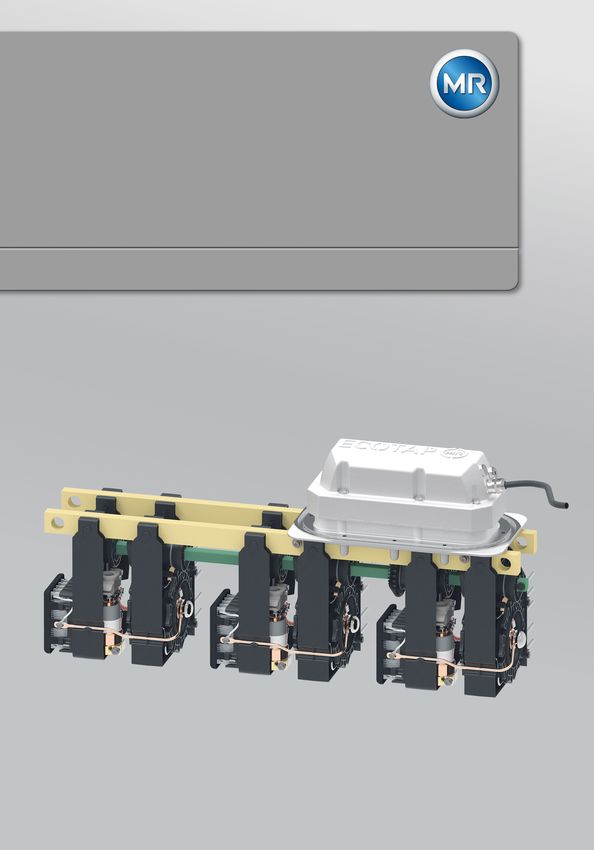
Figure 2: Rear view of the ECOTAP® VPD® without change-over selector
1 Diverter switch assembly with tran- 2 Selector assembly
sition resistor and vacuum inter-
rupter
Maschinenfabrik Reinhausen GmbH 2019 6107891/02 EN ECOTAP® VPD® 193 Product description
3.4.2 ECOTAP® VPD® III with change-over selector
The on-load tap-changer with change-over selector has 17 operating posi-
tions.
Figure 3: Front view of the ECOTAP® VPD® with change-over selector
1 Motor-drive unit 2 Nameplate
3 Sealing module 4 Connection contact
5 O-ring gasket
20 ECOTAP® VPD® 6107891/02 EN Maschinenfabrik Reinhausen GmbH 20193 Product description
Figure 4: Rear view of the ECOTAP® VPD® with change-over selector
1 Diverter switch assembly with tran- 2 Selector assembly
sition resistor and vacuum inter-
rupter
3 Change-over selector assembly
3.4.3 ECOTAP® VPD® I without change-over selector
The 1-phase on-load tap-changer is only available without a change-over se-
lector and has 9 operating positions.
Maschinenfabrik Reinhausen GmbH 2019 6107891/02 EN ECOTAP® VPD® 213 Product description
1-phase on-load tap-changer with connection contacts on the left
Figure 5: Front view, ECOTAP® VPD® I, connection contacts on left
1 Sealing module 2 Motor-drive unit
3 O-ring gasket 4 Connection contact
Figure 6: Rear view, ECOTAP® VPD® I, connection contacts on left
1 Selector assembly 2 Diverter switch assembly with tran-
sition resistor and vacuum inter-
rupter
3 Nameplate
22 ECOTAP® VPD® 6107891/02 EN Maschinenfabrik Reinhausen GmbH 20193 Product description
1-phase on-load tap-changer with connection contacts on the right
Figure 7: Front view, ECOTAP® VPD® I, connection contacts on right
1 Motor-drive unit 2 Nameplate
3 Sealing module 4 Connection contact
5 O-ring gasket
Figure 8: Rear view, ECOTAP® VPD® I, connection contacts on right
1 Diverter switch assembly with tran- 2 Selector assembly
sition resistor and vacuum inter-
rupter
Maschinenfabrik Reinhausen GmbH 2019 6107891/02 EN ECOTAP® VPD® 234 Packaging, transport and storage
4 Packaging, transport and storage
4.1 Packaging
The products are sometimes supplied with sealed packaging and sometimes
in a dry state, depending on requirements.
Sealed packaging surrounds the packaged goods with plastic foil on all
sides.
Products that have also been dried are identified by a yellow label on the
sealed packaging. In the dry state, delivery is also possible in a transport
container.
The information in the following sections should be applied as appropriate.
4.1.1 Suitability
NOTICE Property damage due to incorrectly stacked crates!
Stacking the crates incorrectly can lead to damage to the packaged goods.
► The outer marking on the packaging states if, for example, the on-load
tap-changer or selector has been packed upright. Never stack these
crates.
► General rule: Do not stack crates above a height of 1.5 m.
► For other crates: Only stack up to 2 equally sized crates on top of one an-
other.
The packaging is suitable to ensure undamaged and fully functional means
of transportation in compliance with local transportation laws and regula-
tions.
The packaged goods are packed in a sturdy crate. This crate ensures that,
when in the intended transportation position, the packaged goods are stabi-
lized to prevent impermissible changes in position, and that none of the parts
touch the loading surface of the means of transport or touch the ground after
unloading.
Sealed packaging surrounds the packaged goods with plastic foil on all
sides. The packaged goods are protected from humidity using a desiccant.
The plastic foil was bonded after the desiccant is added.
24 ECOTAP® VPD® 6107891/02 EN Maschinenfabrik Reinhausen GmbH 20194 Packaging, transport and storage
4.1.2 Markings
The packaging bears a signature with instructions for safe transport and cor-
rect storage. The following symbols apply to the shipment of non-hazardous
goods. Adherence to these symbols is mandatory.
Protect against Top Fragile Attach lifting Center of mass
moisture gear here
Table 5: Shipping pictograms
4.2 Transportation, receipt and handling of shipments
WARNING Danger of death and damage to property!
Danger of death and damage to property due to tipping or falling load.
► Only transport the crate when closed.
► Do not remove the securing material used in the crate during transport.
► If the product is delivered on a pallet, secure it sufficiently.
► Only trained and authorized persons may select the sling gear and se-
cure the load.
► Do not walk under the hanging load.
► Use means of transport and lifting gear with a sufficient carrying capacity
in accordance with the weight stated on the delivery slip.
In addition to oscillation stress, jolts must also be expected during trans-
portation. In order to prevent possible damage, avoid dropping, tipping,
knocking over and colliding with the product.
If a crate tips over, falls from a certain height (e.g. when slings tear) or is
subject to an unbroken fall, damage must be expected regardless of the
weight.
Every delivered shipment must be checked for the following by the recipient
before acceptance (acknowledgment of receipt):
▪ Completeness based on the delivery slip
▪ External damage of any type
The checks must take place after unloading when the crate or transport con-
tainer can be accessed from all sides.
Maschinenfabrik Reinhausen GmbH 2019 6107891/02 EN ECOTAP® VPD® 254 Packaging, transport and storage
Visible damage If external transport damage is found upon receipt of the shipment, proceed
as follows:
▪ Immediately record the identified transport damage in the shipping docu-
ments and have this countersigned by the carrier.
▪ In the event of severe damage, total loss or high damage costs, immedi-
ately notify the manufacturer and the relevant insurance company.
▪ After identifying damage, do not modify the condition of the shipment fur-
ther and retain the packaging material until an inspection decision has
been made by the transport company or the insurance company.
▪ Record the details of the damage immediately on site together with the
carrier involved. This is essential for any claim for damages.
▪ Photograph damage to packaging and packaged goods. This also applies
to signs of corrosion on the packaged goods due to moisture inside the
packaging (rain, snow, condensation).
▪ NOTICE! If the product is delivered in sealed packaging, inspect this im-
mediately. If the sealed packaging is damaged, do not under any circum-
stances install or commission the packaged goods. Either re-dry the dried
packaged goods as per the operating instructions, or contact the manu-
facturer to agree on how to proceed. Failure to do so may result in dam-
age to the packaged goods.
▪ Identify the damaged parts.
Hidden damage When damages are not determined until unpacking after receipt of the ship-
ment (hidden damage), proceed as follows:
▪ Make the party responsible for the damage liable as soon as possible by
telephone and in writing, and prepare a damage report.
▪ Observe the time periods applicable to such actions in the respective
country. Inquire about these in good time.
With hidden damage, it is very hard to make the transportation company (or
other responsible party) liable. Any insurance claims for such damages can
only be successful if relevant provisions are expressly included in the insur-
ance terms and conditions.
4.3 Storage of shipments
Packaged goods dried by Maschinenfabrik Reinhausen
Upon receipt of the shipment, immediately remove the packaged goods
dried by Maschinenfabrik Reinhausen from the sealed packaging and store
air-tight in dry insulating oil until used if the packaged goods were not sup-
plied in oil.
Non-dried packaged goods
Non-dried packaged goods but with a functional sealed packaging can be
stored outdoors when the following conditions are complied with.
26 ECOTAP® VPD® 6107891/02 EN Maschinenfabrik Reinhausen GmbH 20194 Packaging, transport and storage
When selecting and setting up the storage location, ensure the following:
▪ Protect stored goods against moisture (flooding, water from melting snow
and ice), dirt, pests such as rats, mice, termites and so on, and against
unauthorized access.
▪ Store the crates on timber beams and planks as a protection against ris-
ing damp and for better ventilation.
▪ Ensure sufficient carrying capacity of the ground.
▪ Keep entrance paths free.
▪ Check stored goods at regular intervals. Also take appropriate action after
storms, heavy rain or snow and so on.
Protect the packaging foil from direct sunlight so that it does not disintegrate
under the influence of UV rays, which would cause the packaging to lose its
sealing function.
If the product is installed more than 6 months after delivery, suitable mea-
sures must be taken without delay. The following measures can be used:
▪ Correctly regenerate the drying agent and restore the sealed packaging.
▪ Unpack the packed goods and store in a suitable storage space (well ven-
tilated, as dust-free as possible, humidity < 50% where possible).
4.4 Unpacking shipments and checking for transportation
damages
▪ NOTICE! Transport the packaged crate to the place where installation will
take place. Do not open the sealed packaging until just before installation.
If this is not done, damage to the packaged goods may occur due to inef-
fectively sealed packaging.
▪ WARNING! When unpacking, check the condition of the packaged
goods.Secure packaged goods in an upright crate from tipping out. If this
is not done, the packaged goods may be damaged and serious injuries
may result.
▪ Check completeness of supplementary parts on the basis of the delivery
slip.
Maschinenfabrik Reinhausen GmbH 2019 6107891/02 EN ECOTAP® VPD® 275 Mounting
5 Mounting
5.1 Fastening on-load tap-changer to transformer cover
NOTICE Damage to the on-load tap-changer and transformer!
Damage to on-load tap-changer and transformer due to electrical flashover
caused by insufficient distance from the motor-drive unit!
► When positioning the opening in the transformer, ensure a sufficient dis-
tance from adjacent energized parts.
Mount the on-load tap-changer horizontally with the sealing module on the
transformer cover.
Do not paint the surface on the underside of the transformer cover, which
later makes contact with the sealing module's o-ring. Only one coating of
primer is permitted.
1. Make opening for sealing module and holes for fixing screws in the trans-
former cover. The measurements and position can be found in the dimen-
sional drawing in the appendix.
2. Clean sealing surfaces on sealing module and underside of transformer
cover. Insert O-ring supplied in sealing module.
3. CAUTION! Gradually tighten screws crosswise as described below
without warping or deforming. Improper screw connection will result in
damage to the on-load tap-changer.
4. Guide on-load tap-changer from below through the opening in the trans-
former cover.
5. Evenly tighten screws crosswise by hand. Tighten screws crosswise with
a pre-tightening torque of 9 Nm.
6. Check seat of flange and seal for regularity.
7. Tighten screws crosswise with the full tightening torque of 16 Nm.
8. Tighten screws again with full tightening torque, working clockwise and
tightening one screw after another as far as each screw will go.
5.1.1 Attaching the ECOTAP® VPD® III
NOTICE Damage to the on-load tap-changer and transformer!
The on-load tap-changer may only be operated in transformers that are
completely filled with insulating fluid. Non-compliance may result in voltage
flashovers that cause serious damage to the on-load tap-changer and trans-
former.
► Use in hermetic transformers with a gas cushion below the transformer
cover is only permitted with an appropriate special design.
28 ECOTAP® VPD® 6107891/02 EN Maschinenfabrik Reinhausen GmbH 20195 Mounting
Mount the on-load tap-changer horizontally with the sealing module on the
transformer cover.
Do not paint the surface on the underside of the transformer cover, which
later makes contact with the sealing module's o-ring. Only one coating of
primer is permitted.
1. Make opening for sealing module and holes for fixing screws in the trans-
former cover. The measurements and position can be found in the dimen-
sional drawing in the appendix.
Figure 9: Top view of transformer cover with opening for sealing module
Maschinenfabrik Reinhausen GmbH 2019 6107891/02 EN ECOTAP® VPD® 295 Mounting
2. Clean sealing surfaces on sealing module and underside of transformer
cover. Insert O-ring supplied in sealing module.
Figure 10: O-ring gasket
3. CAUTION! Gradually tighten screws crosswise as described below
without warping or deforming. Improper screw connection will result in
damage to the on-load tap-changer.
4. Guide on-load tap-changer from below through the opening in the trans-
former cover.
5. Evenly tighten screws crosswise by hand. Tighten screws crosswise with
a pre-tightening torque of 9 Nm.
6. Check seat of flange and seal for regularity.
30 ECOTAP® VPD® 6107891/02 EN Maschinenfabrik Reinhausen GmbH 20195 Mounting
7. Tighten screws crosswise with the full tightening torque of 16 Nm.
Figure 11: Fastening the on-load tap-changer
Pre-tightening torque 9 Nm
Full tightening torque 16 Nm
8. Tighten screws again with full tightening torque, working clockwise and
tightening one screw after another as far as each screw will go.
Maschinenfabrik Reinhausen GmbH 2019 6107891/02 EN ECOTAP® VPD® 315 Mounting
5.1.2 Attaching the ECOTAP® VPD® I
NOTICE Damage to the on-load tap-changer and transformer!
The on-load tap-changer must be fully immersed in insulating fluid. Ener-
gized parts of the on-load tap-changer coming into contact with air may re-
sult in voltage flashovers that cause serious damage to the on-load tap-
changer and transformer.
► Use in hermetic transformers with a gas cushion is only permitted if there
is sufficient distance between the gas cushion and the on-load tap-
changer and connection contacts.
► The distance to the gas cushion must ensure that the on-load tap-
changer is fully immersed in insulating fluid in every operating situation.
Mount the on-load tap-changer vertically with the sealing module on the
transformer side wall.
Do not paint the inner surface of the transformer side wall which will later
make contact with the sealing module o-ring. Only one coating of primer is
permitted.
1. Make an opening for the sealing module and holes for the fixing screws
on the transformer side wall. The measurements and position can be
found in the dimensional drawing in the appendix.
Figure 12: View of the transformer side wall with opening for sealing module
32 ECOTAP® VPD® 6107891/02 EN Maschinenfabrik Reinhausen GmbH 20195 Mounting
2. Clean the sealing surfaces on the sealing module and the transformer
side wall. Insert O-ring supplied in sealing module.
Figure 13: O-ring gasket
3. CAUTION! Gradually tighten screws crosswise as described below
without warping or deforming. Improper screw connection will result in
damage to the on-load tap-changer.
4. Lead the on-load tap-changer sideways from the inside through the open-
ing in the transformer side wall.
5. Evenly tighten screws crosswise by hand. Tighten screws crosswise with
a pre-tightening torque of 9 Nm.
6. Check seat of flange and seal for regularity.
Maschinenfabrik Reinhausen GmbH 2019 6107891/02 EN ECOTAP® VPD® 335 Mounting
7. Tighten screws crosswise with the full tightening torque of 16 Nm.
Figure 14: Fastening the on-load tap-changer
Pre-tightening torque 9 Nm
Full tightening torque 16 Nm
8. Tighten screws again with full tightening torque, working clockwise and
tightening one screw after another as far as each screw will go.
34 ECOTAP® VPD® 6107891/02 EN Maschinenfabrik Reinhausen GmbH 20195 Mounting
5.2 Connecting tap winding and on-load tap-changer take-off
lead
NOTICE Damage to the on-load tap-changer caused by improper mount-
ing!
Mounting mistakes will damage the on-load tap-changer and jeopardize
safe operation.
► Connect connecting leads without warping or deforming them and ensure
that no forces are transferred from the connecting leads to the on-load
tap-changer.
► Place at least 3 mm of paper insulation on the connecting leads – includ-
ing connection points – that face the transformer cover or the transformer
side wall to ensure the dielectric strength.
► Bending the connection contacts may limit the dielectric strength in accor-
dance with the specification in the "Technical data" [►Section 11.4, Page
69] chapter and reduce the rated withstand voltages! Ensure that the di-
electric strength needed for the application is still ensured after assembly.
► The diagram below shows the areas particularly critical for insulation
spacing. Avoid bending the connection contacts into these critical areas.
ECOTAP® VPD® III on-load tap-changer without change-over selector
Figure 15: Insulation spacing for ECOTAP® VPD® III without change-over selector
1 Transformer cover
2 Critical area: Spacing to grounded parts
3 Critical area: Spacing between the phases
Maschinenfabrik Reinhausen GmbH 2019 6107891/02 EN ECOTAP® VPD® 355 Mounting
ECOTAP® VPD® III on-load tap-changer with change-over selector
Figure 16: Insulation spacing for ECOTAP® VPD® III with change-over selector
1 Transformer cover
2 Critical area: Spacing to grounded parts
3 Critical area: Spacing between the phases
36 ECOTAP® VPD® 6107891/02 EN Maschinenfabrik Reinhausen GmbH 20195 Mounting
ECOTAP® VPD® I on-load tap-changer without change-over selector
Figure 17: Insulation spacing for ECOTAP® VPD® I without change-over selector
1 Transformer side wall
2 Supporting bar
3 Critical area: Spacing to grounded parts
NOTICE Damage to on-load tap-changer due to improperly carried out
crimp connections!
Improperly carried out crimp connections jeopardize safe operation.
► Carry out crimp connections in accordance with DIN EN 61238-1.
► The connection contacts on crimp connections may be shortened by no
more than 6 cm.
Maschinenfabrik Reinhausen GmbH 2019 6107891/02 EN ECOTAP® VPD® 375 Mounting
NOTICE Damage to on-load tap-changer due to improperly carried out
solder connections!
Improperly carried out solder connections jeopardize safe operation.
► The connection contacts may not be shortened.
► The solder connection may only be produced on the end of the connec-
tion contacts (approx. 30 mm).
► Depending on the materials used, ensure the correct application of heat
to prevent both cold solder spots and thermal damage to the on-load tap-
changer.
► Ensure that sharp edges or points are not produced at the connection
points. These may cause a local concentration of the field strength and
therefore result in partial discharge.
► Remove flux material residue.
Taking these safety notices into consideration, you can establish the con-
nections in accordance with the supplied order-specified connection dia-
gram. This connection diagram also contains the exact assignment of the in-
dividual connecting pieces of the on-load tap-changer.
1. To do so, connect the leads for the tap winding and on-load tap-changer
take-off leads to the on-load tap-changer's connection contacts by means
of crimping or soldering, without twisting.
Figure 18: Tap winding connection (example for ECOTAP® VPD® III)
38 ECOTAP® VPD® 6107891/02 EN Maschinenfabrik Reinhausen GmbH 20195 Mounting
Figure 19: Tap winding connection (example for ECOTAP® VPD® I)
2. If the connection contacts have to be bent, observe the aforementioned
safety notices and use additional pliers to hold in place during bending so
that none of the forces are transferred to the on-load tap-changer. For
reasons of accessibility, we recommend starting with the bottom connec-
tions.
If you have any questions about producing the connections, please contact
Maschinenfabrik Reinhausen GmbH's Technical Service department.
5.3 Mounting motor-drive unit and control unit
As preparation, you must ensure that the on-load tap-changer is in a defined
operating position.
1. DANGER! Check the operating position before the transformer is
commissioned or ensure that the transformer is disconnected from all volt-
age sources and secured against reconnection. Failure to do so can lead
to death or serious injuries.
Maschinenfabrik Reinhausen GmbH 2019 6107891/02 EN ECOTAP® VPD® 395 Mounting
2. Remove transport locking plate and store safely. To avoid contamination
and mechanical damage, do not leave the sealing module open for long
periods of time.
Figure 20: Removing the transport locking plate
3. When mounting for the first time: remove label with warning.
Figure 21: Removing the label
40 ECOTAP® VPD® 6107891/02 EN Maschinenfabrik Reinhausen GmbH 20195 Mounting
4. Check the position of the on-load tap-changer: The current operating posi-
tion is displayed by the control wheel.
Figure 22: Checking operating position (exemplary illustration)
5. Check additionally the position of the shaft of the on-load tap-changer: If
the previous on-load tap-change operation has been finished correctly,
the arrow on the cam disk is pointing to the arrow in the cover .
Figure 23: Position of the shaft of the on-load tap-changer
ð If the shaft of the on-load tap-changer is in this position, the on-load
tap-changer is in a defined operating position. If this is not the case,
correct the position as described below.
6. NOTICE! Only use the emergency drive shaft installed in the sealing
module. Failure to do so can result in damage to the on-load tap-changer.
Maschinenfabrik Reinhausen GmbH 2019 6107891/02 EN ECOTAP® VPD® 415 Mounting
7. Pull the emergency drive shaft out of the bracket in the sealing module.
Figure 24: Removing emergency drive shaft
8. Plug the emergency drive shaft with feather key into the shaft of the on-
load tap-changer.
Figure 25: Attaching emergency drive shaft
9. Rotate emergency drive shaft in direction of desired operating position us-
ing an appropriate tool.
Figure 26: Emergency drive shaft actuation
42 ECOTAP® VPD® 6107891/02 EN Maschinenfabrik Reinhausen GmbH 20195 Mounting
10. NOTICE! Using the emergency drive shaft, turn for every tap-change
operation in one direction until one revolution has been completed and
the arrow on the cam disk (1) is again pointing to the arrow in the cover
(2). Otherwise the tap-change operation is not completed correctly,
which may result in damage to the on-load tap-changer and transformer.
Figure 27: Position of the shaft of the on-load tap-changer
ð The current operating position is displayed by the control wheel.
Figure 28: Checking operating position (exemplary illustration)
11. Pull the emergency drive shaft out of the shaft of the on-load tap-
changer and plug it back into the bracket.
Figure 29: Plugging the emergency drive shaft back in
12. Close the sealing module with the transport locking plate if the motor-
drive unit is not to be mounted immediately.
Maschinenfabrik Reinhausen GmbH 2019 6107891/02 EN ECOTAP® VPD® 43You can also read