Product Manual SMART CONNECT KNX Remote Access 1-0003-004 - ise ...
←
→
Page content transcription
If your browser does not render page correctly, please read the page content below
Product Manual
SMART CONNECT KNX Remote Access
1-0003-004

Documentation valid for:
Product database entry:     v6.1
Firmware:                   v6.1
SDA client:                 from v1.6
Document issued:            25.05.2021

© 2021 ise Individuelle Software und Elektronik GmbH
Contents

Contents

1         About this documentation ........................................................................................ 4
1.1       Target group......................................................................................................................... 4
1.2       Symbols and typographical conventions ........................................................................... 4
2         About SMART CONNECT KNX Remote Access ......................................................... 5
2.1       Proper use ............................................................................................................................ 5
2.2       System.................................................................................................................................. 6
2.3       Functions and use cases .................................................................................................... 6
2.4       Using the SDA portal server ................................................................................................ 8
2.5       SDA client ........................................................................................................................... 11
2.5.1     General SDA client settings............................................................................................... 12
2.5.2     Establishing a connection using a portal login................................................................ 13
2.5.3     Establishing a connection with Quick Connect ............................................................... 15
2.5.4     The SDA client’s remote access options ......................................................................... 16
3         Important notes...................................................................................................... 18
3.1       General safety instructions ............................................................................................... 18
3.2       Storage and transport........................................................................................................ 18
3.3       Cleaning and maintenance ............................................................................................... 18
4         Technical data........................................................................................................ 19
5         Device design ......................................................................................................... 20
5.1       Front ................................................................................................................................... 20
5.2       Data on device sticker ....................................................................................................... 21
5.3       Top...................................................................................................................................... 21
5.4       Underside ........................................................................................................................... 22
5.5       Device side ......................................................................................................................... 22
6         Installation ............................................................................................................. 23
6.1       Scope of supply ................................................................................................................. 23
6.2       Checking the installation conditions ................................................................................ 24
6.3       Mounting the device .......................................................................................................... 25
7         Device website ....................................................................................................... 29
7.1       Device website: Calling up the start screen ..................................................................... 29
7.2       Getting to know the interface of the device website ....................................................... 30
8         Commissioning and configuration .......................................................................... 32
8.1       Quick start .......................................................................................................................... 32
8.2       Reading off the device status using the LEDs ................................................................. 33
8.2.1     LEDs during device start-up .............................................................................................. 35
8.2.2     LEDs in operation............................................................................................................... 36
8.3       Configuration ..................................................................................................................... 37
8.3.1     Creating the device in the ETS .......................................................................................... 38
8.3.2     IP settings .......................................................................................................................... 40
8.3.3     Programming an individual address................................................................................. 41
8.3.4     Network settings via the device website.......................................................................... 43
8.3.5     Resetting to factory settings............................................................................................. 43
8.4       Updating firmware ............................................................................................................. 45
8.4.1     Updating the firmware via the device website................................................................. 45
8.4.2     Compatibility between product database entry and firmware version .......................... 47
8.5       Firewall configuration........................................................................................................ 49
8.6       Setting up VPN................................................................................................................... 49
9         Configuring parameters.......................................................................................... 51
9.1       Parameters – general........................................................................................................ 52
9.1.1     DNS server (if not using DHCP) ........................................................................................ 53
9.1.2     Controlling VPN access via KNX ...................................................................................... 53
9.1.3     Time server ........................................................................................................................ 53
9.1.4     Data logger ......................................................................................................................... 53

SMART CONNECT KNX Remote Access                                                                                                                1-0003-004
© 2021 ise Individuelle Software und Elektronik GmbH                                                                                              p. 1 / 93
Contents

9.1.5     Time zone........................................................................................................................... 54
9.1.6     General portal access after restart................................................................................... 54
9.1.7     Remote access after restart ............................................................................................. 55
9.1.8     Number of notification objects ......................................................................................... 55
9.2       Parameter – time server ................................................................................................... 56
9.3       Parameter – data logger ................................................................................................... 57
9.4       Parameter – notifications ................................................................................................. 60
10        Group objects ......................................................................................................... 63
10.1      Remote access .................................................................................................................. 63
10.2      Connection error ................................................................................................................ 68
10.3      Time server ........................................................................................................................ 70
10.4      Data logger ......................................................................................................................... 72
10.5      Notifications....................................................................................................................... 75
11        Troubleshooting ..................................................................................................... 77
11.1      Generating log files............................................................................................................ 78
11.2      Contacting Support............................................................................................................ 79
11.3      FAQs – Frequently asked questions ................................................................................ 80
12        Disassembly and disposal ...................................................................................... 83
13        Glossary ................................................................................................................. 85
14        Licence Agreement SMART CONNECT KNX Remote Access................................... 89
14.1      Definitions .......................................................................................................................... 89
14.2      Object of the agreement.................................................................................................... 89
14.3      Software usage rights ....................................................................................................... 89
14.3.1    Firmware and SDA client ................................................................................................... 89
14.3.2    Secure Device Access portal ............................................................................................ 89
14.4      Restriction of rights of use................................................................................................ 90
14.4.1    Maximum permissible transfer volume ........................................................................... 90
14.4.2    Copying, modification and transmission ......................................................................... 90
14.4.3    Reverse engineering and conversion technologies......................................................... 90
14.4.4    Firmware and hardware .................................................................................................... 90
14.4.5    Transfer to a third party..................................................................................................... 90
14.4.6    Renting out, leasing out and sub-licensing ...................................................................... 90
14.4.7    Software creation .............................................................................................................. 90
14.4.8    The mechanisms of licence management and copy protection .................................... 90
14.5      Property and confidentiality .............................................................................................. 91
14.5.1    Documentation .................................................................................................................. 91
14.5.2    Transfer to a third party..................................................................................................... 91
14.6      Modifications and subsequent deliveries ........................................................................ 91
14.7      Warranty ............................................................................................................................. 91
14.7.1    Software and documentation ........................................................................................... 91
14.7.2    Limitation of warranty ....................................................................................................... 91
14.8      Liability ............................................................................................................................... 92
14.9      Applicable law.................................................................................................................... 92
14.10     Termination ........................................................................................................................ 92
14.11     Subsidiary agreements and changes to the agreement ................................................. 92
14.12     Exception............................................................................................................................ 92
15        Open Source Software ............................................................................................ 93

SMART CONNECT KNX Remote Access                                                                                                                1-0003-004
© 2021 ise Individuelle Software und Elektronik GmbH                                                                                              p. 2 / 93
Legal Information

Legal Information

SMART CONNECT KNX Remote Access Product Manual
Status: 25.05.2021

ise Individuelle Software und Elektronik GmbH
Osterstraße 15
26122 Oldenburg, Germany
© Copyright 2021 ise Individuelle Software und Elektronik GmbH

All rights reserved. No part of this document may be edited, copied, disseminated or made public in any
form (print, photocopy or any other method) without the prior written permission of ise Individuelle Soft-
ware und Elektronik GmbH.

Products to which reference is made in this document can be either brands or registered trademarks of
the respective rights holder. Ise Individuelle Software und Elektronik GmbH and the author make no
claim to these brands. The brands are named solely for the purpose of providing the necessary descrip-
tion.

Trademark

KNX is a registered trademark of the KNX Association.

Feedback and information about products

               If you have any questions regarding our products, please contact us via e-
               mail at sales@ise.de. We would be pleased to receive your ideas, sugges-
               tions for improvements and criticism via e-mail at support@ise.de.

SMART CONNECT KNX Remote Access                                                                1-0003-004
© 2021 ise Individuelle Software und Elektronik GmbH                                              p. 3 / 93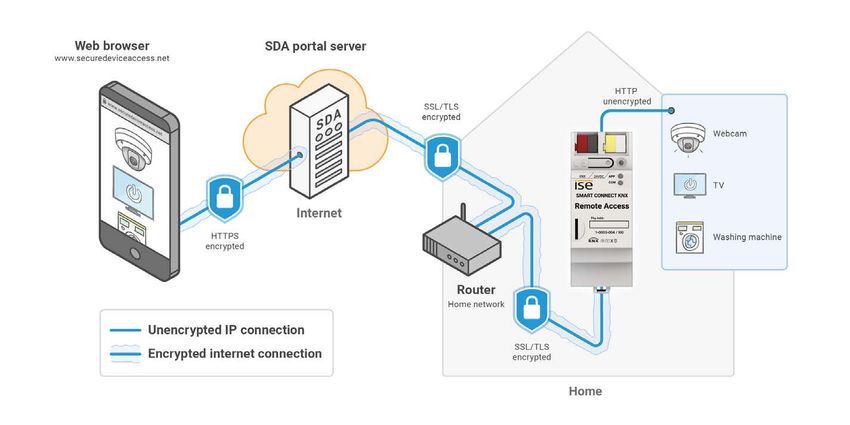
About this documentation

1          About this documentation

This documentation will accompany you through all phases of the product life cycle of SMART CON-
NECT KNX Remote Access. You will learn for example how to assemble, install, commission and con-
figure the device.

All descriptions in this documentation relating to configuration in the ETS refer to the variant "ETS Pro-
fessional" in the version 5.

Explanations for the concepts of KNX do not form part of this documentation.

1.1        Target group
This documentation is aimed at qualified electricians and KNX processors.

             Only qualified electricians may assemble and install the SMART CONNECT KNX Remote Ac-
             cess. Specialist knowledge of KNX is a prerequisite.

             Anyone may configure the SMART CONNECT KNX Remote Access. We recommend that con-
             figuration is done by a system integrator with sound specialist knowledge of KNX and using
             the ETS.

1.2        Symbols and typographical conventions

             Symbol / label                                      Meaning

                                    Warning of possible material damage

                                    General warning

                                    Warning of electrical voltage

    Table 1: Symbols and safety notes

             Symbol / label                                      Meaning

      F1                            PC button

                     Text on software interface

                                    Troubleshooting tip

                                    Important additional information

    Table 2: Special symbols and typographical conventions

SMART CONNECT KNX Remote Access                                                                1-0003-004
© 2021 ise Individuelle Software und Elektronik GmbH                                              p. 4 / 93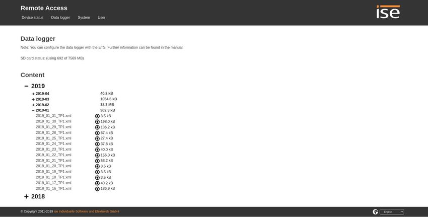
About SMART CONNECT KNX Remote Access

2       About SMART CONNECT KNX Remote Access

2.1     Proper use
The SMART CONNECT KNX Remote Access enables safe remote access to your KNX installation. A
VPN connection can also be established with your Ethernet-based home network. In order to carry out
remote maintenance with the ETS, the SDA client for Windows gives you access to:

•   the IP interfaces in the KNX installation
•   the devices contained in the remote network.

The SMART CONNECT KNX Remote Access is a KNX system device and complies with the KNX guide-
lines.

               Important

      ise Individuelle Software und Elektronik GmbH assumes no liability for damage caused by
      improper use or use for purposes other than or contrary to the intended purpose.

Configuration: Compatible ETS versions

Simple integration into the KNX System (can be completely configured via ETS):

•   ETS5 or higher;
•   Product database entry: Download the product database entry from our website www.ise.de or from
    the ETS online catalogue free of charge.

KNX Secure

                  SMART CONNECT KNX Remote Access is KNX Secure.

                  The device is compatible with KNX Secure. KNX Secure offers protection against
                  manipulation in building automation and can be configured in the ETS project.

•   The required KNX Secure certificate or the FDSK (Factory Default Setup Key) that it contains can be
    found on a sticker on the side of the device and is also enclosed with the device.

•   For maximum security, we recommend removing the sticker from the device.

•   Keep the certificate in a safe place.

•   You cannot restore the certificate yourself.

•   Please contact our support team if you should lose the certificate despite utmost care.

SMART CONNECT KNX Remote Access                                                               1-0003-004
© 2021 ise Individuelle Software und Elektronik GmbH                                             p. 5 / 93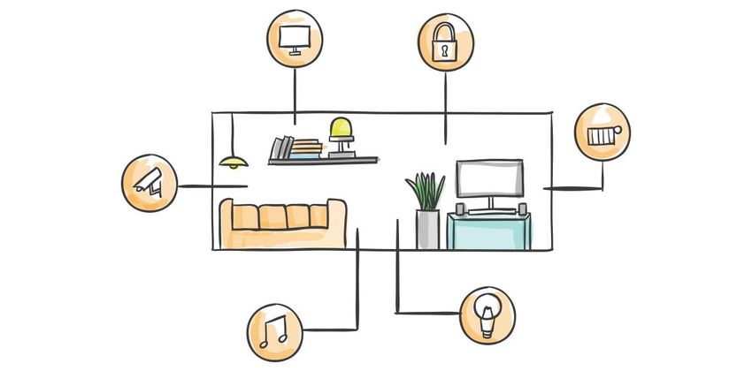
About SMART CONNECT KNX Remote Access
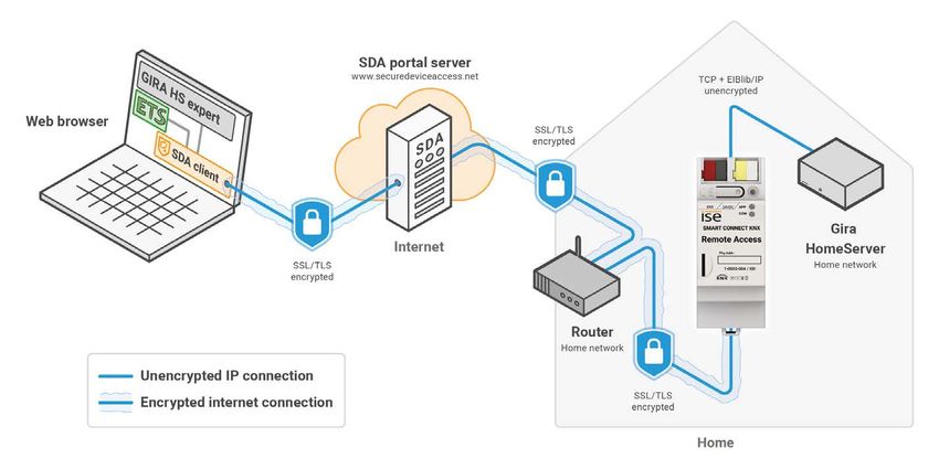
2.2 System
The SMART CONNECT KNX Remote Access is connected to the KNX installation via KNX/TP.
The device is connected to the Internet via IP in order to enable access to the KNX system.
The remote access is configured using the Secure Device Access (SDA) on the SDA portal at
https://securedeviceaccess.net.
Communication between the SMART CONNECT KNX Remote Access and the SDA portal server is
encrypted as per AES specifications and is secured with digital certificates.
Figure 1: Remote access system chart
2.3 Functions and use cases
• To access the KNX devices remotely, connect the SMART CONNECT KNX Remote Access with the
KNX installation.
• The SMART CONNECT KNX Remote Access is connected to the home network over Ethernet.
It then connects to the SDA portal server automatically through your existing Internet access
https://securedeviceaccess.net ► see Using the SDA portal server, p. 8
• Use as a data logger. The SMART CONNECT KNX Remote Access features a card reader for micro-
SDHC cards up to 32 GB. The KNX telegrams in an ETS5 format can be recorded on the card for anal-
ysis purposes. The card memory can be used as a ring memory or as a read-only memory.
• Use as a time server. The SMART CONNECT KNX Remote Access can transmit the time and date to
the bus at configurable intervals. It is possible to initiate transmission of the current time and the cur-
rent date using a trigger.
• Among other things, VPN network coupling (either Layer 2 or Layer 3) provides access to KNX instal-
lations, visualization interfaces and files in the home network. This means uncomplicated access to
the KNX system and other applications is also possible for smartphone apps. The VPN access can
be controlled and monitored via KNX group objects.
SMART CONNECT KNX Remote Access 1-0003-004
© 2021 ise Individuelle Software und Elektronik GmbH p. 6 / 93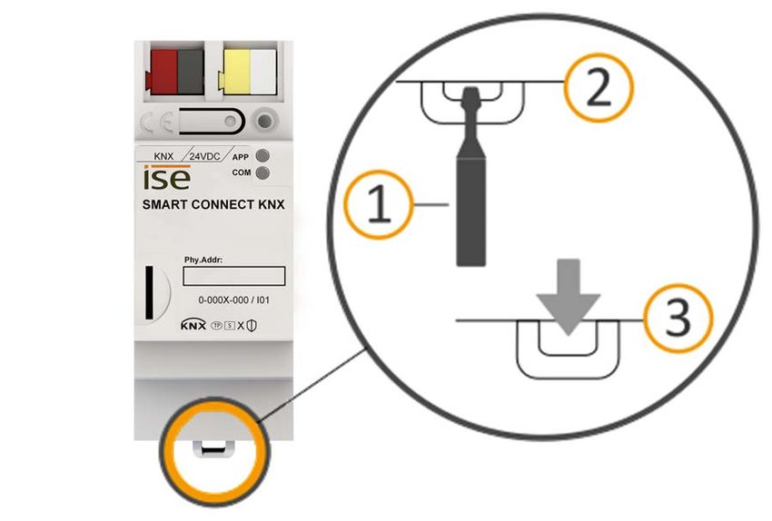
About SMART CONNECT KNX Remote Access

•   Administration of remote access options and access rights on the SDA portal ► see SDA portal func-
    tions, p. 9

•   Access to the HTML pages from any networked end device ► see Access to websites in the remote
    network, p. 10

•   KNX communication with the ETS via KNXnet/IP, IP direct download and Eiblib/IP via the SDA client
    ► see The SDA client’s remote access options, p. 16

•   Configuration access to the Gira HomeServer with the HomeServer Expert via the SDA client.

•   Access to Windows computers using the remote desktop connection through the SDA client.

•   Freely configurable TCP port redirects via the SDA client for Windows.

•   Notifications can be triggered via KNX telegrams, saved to the SDA portal server and forwarded by
    means such as an e-mail, a phone call or text message.

•   KNX/TP connection with integrated IP interface (tunnelling server) for KNX access using ETS or other
    software. Three concurrent connections can be set up for using the download and the groups and
    bus monitor.

•   Status signalling and access management of the secured connections using KNX group objects.

•   Secure Device Access also functions via a mobile phone network access even if it does not have a
    unique IP address accessible from the outside, as is usually the case for UMTS or LTE.

•   For your internet router, communication from your SMART CONNECT KNX Remote Access will not
    differ from an encrypted connection in your browser, in a similar way to online banking, for example.

Functional enhancements from updates

You can obtain functional enhancements for the SMART CONNECT KNX Remote Access with a new ver-
sion of the firmware. Simply download the latest firmware and the relevant product manual from our
website www.ise.de.

► see Updating the firmware via the device website, p. 45

SMART CONNECT KNX Remote Access                                                               1-0003-004
© 2021 ise Individuelle Software und Elektronik GmbH                                             p. 7 / 93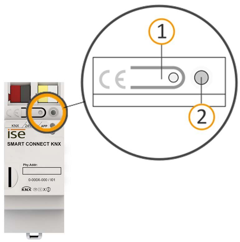
About SMART CONNECT KNX Remote Access
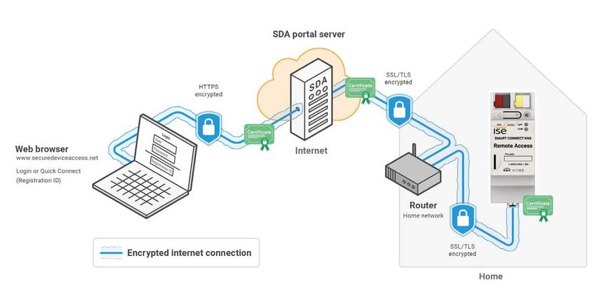
2.4 Using the SDA portal server
The SDA portal server and the SDA portal can be accessed at https://securedeviceaccess.net.
The SDA portal server acts as the point of exchange during remote access to the end devices in your
building.
The SMART CONNECT KNX Remote Access uses the standard protocols HTTPS, TLS/SSL and Web-
Socket to communicate with the SDA portal server. The SDA portal server does not save the transmitted
data. It merely forwards them instead. The server is operated in Germany in compliance with the strict
European data protection guidelines.
Note on cookies
Use of the SDA portal server requires the use of cookies in the browser for techni-
cal reasons.
You have the following options to use the SDA portal server:
• Registration of a new user for initial login.
• Login as an existing registered SDA portal user.
• Use of HTTP access via Quick Connect using a registration ID.
Figure 2: Overview of secure access with “Secure Device Access“
SMART CONNECT KNX Remote Access 1-0003-004
© 2021 ise Individuelle Software und Elektronik GmbH p. 8 / 93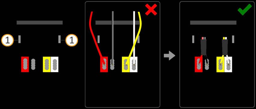
About SMART CONNECT KNX Remote Access

Quick Connect versus portal login

In the case of Quick Connect, you need to enter the registration ID to gain remote access. This has the
advantage of not needing to log a user onto the SDA portal. One use case would be a SMART CONNECT
KNX Remote Access on a construction site connected to a UMTS/LTE router which all co-workers can
use quickly and easily.

In contrast, any number of SMART CONNECT KNX Remote Accesss can be assigned to a user account
on the SDA portal.

You can link your SMART CONNECT KNX Remote Access to an account on the SDA portal server at any
time to prevent access using Quick Connect. Access is then no longer possible via "Quick Connect" un-
less you enable this explicitly again.

All access options are available (ETS, HTTP, Gira HomeServer, etc.) no matter whether Quick Connect
or a portal login is used.

SDA portal functions

The following functions are available to manage your SMART CONNECT KNX Remote Access on the
SDA portal:

•   Setting up users and access groups and managing access rights

•   Adding further SDA devices

•   Retrieving device data

•   Configuring the VPN access

•   Creating redirect rules for SDA notifications

•   Accessing SDA notifications received

•   Adding links to access web interfaces in the remote network

•   Setting up application accesses for using supported apps

SMART CONNECT KNX Remote Access                                                              1-0003-004
© 2021 ise Individuelle Software und Elektronik GmbH                                            p. 9 / 93
About SMART CONNECT KNX Remote Access

Access to websites in the remote network

Network devices with an integrated web server, such as cameras or network printers, can be reached via
the SMART CONNECT KNX Remote Access and automatically receive their name under the domain
httpaccess.net.
You can access the network device concerned in a web browser using this name. Communication over
the Internet is encrypted and user authentication is verified based on the access rights configured on
the SDA portal server for your SMART CONNECT KNX Remote Access. Configuration is performed on
the SDA portal.

   Figure 3: Secure device access to websites via “Secure Device Access“

SMART CONNECT KNX Remote Access                                                             1-0003-004
© 2021 ise Individuelle Software und Elektronik GmbH                                          p. 10 / 93
About SMART CONNECT KNX Remote Access
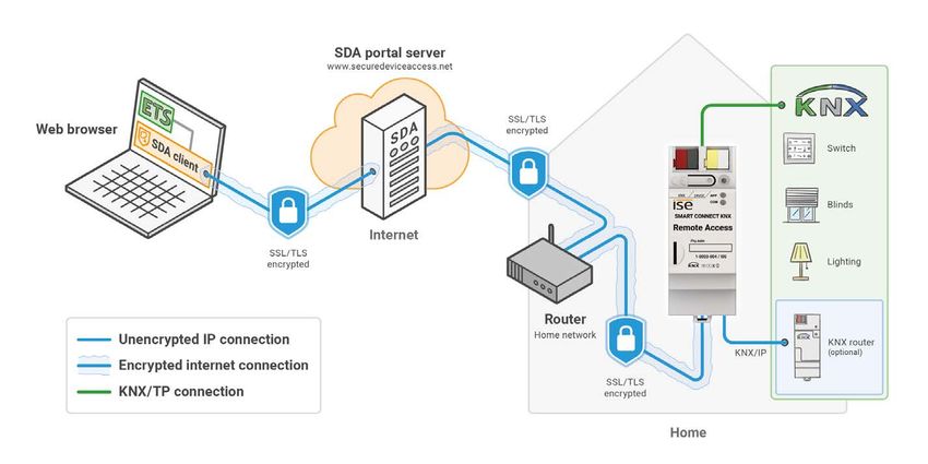
2.5 SDA client
The SDA client is an application that provides secure access to devices on the remote network via the
Internet. To ensure this is the case, the SDA client is installed and launched on the same PC as the ETS.
Figure 4: Secure access to the KNX installation via “Secure Device Access“
The SDA client establishes an encrypted connection to the SMART CONNECT KNX Remote Access via
the SDA portal server. This connection is made available to other applications on your computer and on
your local network so that they can access devices on the remote network.
No SDA client is necessary to access devices using HTTP. You can use the SDA portal directly.
The SDA client is currently available for Microsoft Windows from version 8.
Use cases
The SDA client is used in the following use cases:
• Remote access to KNX installation using the KNX/IP protocol
• Remote configuration of a Gira HomeServer with the HomeServer Expert
• Remote access via other TCP protocols (e.g. remote desktop link RDP)
Connection options
There are two options to establish a connection to the SMART CONNECT KNX Remote Access:
• Portal login (see Establishing a connection using a portal login, p. 13)
• Quick Connect (see Establishing a connection with Quick Connect, p. 15)
SMART CONNECT KNX Remote Access 1-0003-004
© 2021 ise Individuelle Software und Elektronik GmbH p. 11 / 93About SMART CONNECT KNX Remote Access
Installing the SDA client
1. Scroll down to the download section on the product page.
2. Download the appropriate installation file for Windows (x86) or (x64).
3. Execute the installation file on the same PC as the ETS.
2.5.1 General SDA client settings
1. Launch SDA client.
2. Use the gear icon to open the general settings. You will find information on specific settings
in the following table.
Setting Description
Activate ETS access for • Activated: All clients running on the same local network have
the entire local area net- access to the KNX/IP devices.
work (LAN) (only for this • Disabled: The KNX/IP devices are available only to the current cli-
PC apart from that) ent.
The client is the PC on which your ETS is running. The PC is identified
by its IP address. The KNX/IP devices are displayed under in the ETS.
Automatically activate Make this setting if you will use the Gira HomeServer for your projects
secure remote access on a regular basis.
to the Gira Home Server
for new SDA connector
configurations
Check ETS4 version This provides a compatibility check for the ETS4 because the auto-
matic search for KNX/IP connections with ETS versions older than
ETS4.2 may be limited.
Table 3: SDA client settings
SMART CONNECT KNX Remote Access 1-0003-004
© 2021 ise Individuelle Software und Elektronik GmbH p. 12 / 93About SMART CONNECT KNX Remote Access
2.5.2 Establishing a connection using a portal login
Requirement: You are registered as a user on the SDA portal.
1. Launch SDA client.
2. Select as the connection type.
Figure 5: Portal connection type
3. Log on using the same user data as for the SDA portal.
4. Select the required device.
Use the filter if you have multiple devices. Either enter a text or limit the selection
to the devices currently logged onto the SDA portal using the func-
tion.
Figure 6: Device selection for portal Login
5. Select remote access based on your use case. Remote access via KNX/IP is activated by default
(see The SDA client’s remote access options, p. 16).
6. If required, define external commands that should be executed after a connection is established
or cancelled.
Enter the name of the command or program with its path into the left input field. Complete the
input field with all the parameters that need to be transferred to execute the com-
mand.
Figure 7: External commands
Combine external commands using theAbout SMART CONNECT KNX Remote Access
7. Click on after you have defined all the required settings.
You can measure the communication speed if there is an active connection .
What is measured is the time from which a request is transmitted into the target SMART CON-
NECT KNX Remote Access network until a response is received from the SMART CONNECT KNX
Remote Access.
You will find detailed connection information in the logbook .
You can use the button or close the SDA client to disconnect an active connec-
tion.
SMART CONNECT KNX Remote Access 1-0003-004
© 2021 ise Individuelle Software und Elektronik GmbH p. 14 / 93About SMART CONNECT KNX Remote Access
2.5.3 Establishing a connection with Quick Connect
It is not recommended to use Quick Connect for permanent operation for security
reasons. Only use a connection via Quick Connect in exceptional cases, e.g. for
instant remote access directly after the device has been installed.
1. Launch SDA client.
2. Select the connection type .
Figure 8: Quick Connect connection type
3. Enter the device’s registration ID or choose a device that has already been used from the selection
list. The options for remote access will only be displayed if the entry is correct.
4. Select remote access based on your use case. Remote access via KNX/IP is activated as stand-
ard, see The SDA client’s remote access options, p. 16.
5. If required, define external commands that should be executed after a connection is established
or cancelled.
Enter the name of the command or program with its path into the left input field. Complete the
input field with all the parameters that need to be transferred to execute the com-
mand.
Combine external commands using theAbout SMART CONNECT KNX Remote Access
6. Click on after you have defined all the required settings.
You can measure the communication speed if there is an active connection . What is meas-
ured is the time from which a request is transmitted into the target SMART CONNECT KNX
Remote Access network until a response is received from the SMART CONNECT KNX Remote
Access.
You will find detailed connection information in the logbook .
You can use the button or close the SDA client to disconnect an active connec-
tion.
2.5.4 The SDA client’s remote access options
Remote access via KNX/IP
All KNX/TP tunnelling servers and discovered KNX/IP devices in the remote network will appear in the
ETS Connection Manager if remote access is gained via KNX/IP.
Label the discovered KNX/IP devices with a prefix such as SDA- to avoid mixing
them up with other devices in your own network.
Remote access via TCP
If you wish to gain access via a Remote Desktop on a PC, for example, go to the gear icon and enter the
IP or DNS of the target computer in the remote network. It is highly likely that the TCP port in the remote
network (standard port RDP 3389) on your PC is already assigned. In this case, you need to use another
free local TCP port as the standard RDP port. Recommended are ports 40000 and above.
If you have chosen another port as the standard RDP port for the local TCP port,
make the entry for the remote desktop connection as follows:
Example: 127.0.0.1:40000
SMART CONNECT KNX Remote Access 1-0003-004
© 2021 ise Individuelle Software und Elektronik GmbH p. 16 / 93About SMART CONNECT KNX Remote Access
Gira HomeServer remote configuration
Enter either the HomeServer’s IP address or the HomeServer’s local DNS name on the remote network
for remote access to the Gira HomeServer.
You can use the specified default values for the Gira experts. Click on the gear icon if you would like to
change the port specifications anyway. Ports lower than 1023 have usually been assigned and are not
recommended.
Gira HomeServer Version 4.7.0 and above uses Port 443.
As soon as connection has been established via the SDA portal, you can transfer
the project to the HomeServer. To do so, launch the Gira Expert and select the
option in the dialogue. Enter the IP
address 127.0.0.1 and the configured port.
You can use the specified default values in the case of an Eiblib/IP protocol.
Add an connection in the ETS and assign 127.0.0.1 as the server
address and the configured local ports.
Figure 9: Secure Gira HomeServer configuration with “Secure Device Access“
SMART CONNECT KNX Remote Access 1-0003-004
© 2021 ise Individuelle Software und Elektronik GmbH p. 17 / 93Important notes
3 Important notes
3.1 General safety instructions
Warning
Danger from incorrect use
Incorrect use can result in damage to the device, fire or other dangers.
• Only qualified electricians may install and mount electrical devices.
• Follow the instructions in this product manual.
• This product manual is part of the product and must remain with the customer.
3.2 Storage and transport
Store the device in its original packaging. The original packaging provides optimum protection during
transport. Store the device in a temperature range of -25 °C to +70 °C.
3.3 Cleaning and maintenance
The SMART CONNECT KNX Remote Access is maintenance-free.
If necessary, clean the device with a dry cloth.
Important
Device damage due to improper opening
• Never open the housing.
• If you suspect that the device is damaged, contact our support team.
• We provide a warranty in accordance with statutory requirements.
• Send the device back to us postage free with a detailed error description only if our support
team asks you to.
SMART CONNECT KNX Remote Access 1-0003-004
© 2021 ise Individuelle Software und Elektronik GmbH p. 18 / 93Technical data
4 Technical data
Power supply and connections
Rated voltage: DC 24 to 30 V
Supply via external DC
Power consumption: 2W
Connections: • KNX: Bus connection terminal (black/red)
• External power supply: Power supply termi-
nal (white/yellow)
• IP: 2x RJ45 (integrated switch)
microSD card slot microSD cards up to 32 GB (SDHC)
Ambient conditions
Installation environment temperature 0 °C to +45 °C
Device dimensions
Installation width: 36 mm (2 HP)
Installation height: 90 mm
Installation depth: 74 mm (DRA Plus)
KNX SPECIALIST
Communication: • KNX: KNX/TP
• IP: Ethernet 10/100 BaseT (10/100 Mbit/s)
Installation method: S-mode
Approvals and protection type
Approvals / certifications: CE, KNX
Protection type: IP20 (compliant with EN 60529)
Protection class: III (compliant with IEC 61140)
Supported web browsers
Current versions of Mozilla Firefox, Microsoft Edge, Apple Safari and Google Chrome.
SMART CONNECT KNX Remote Access 1-0003-004
© 2021 ise Individuelle Software und Elektronik GmbH p. 19 / 93Device design
5 Device design
Stated directions always relate to the device in its installed position.
5.1 Front
No. Description
2 3 1 Button: Programming button
2 Connection: KNX/TP
1 4 3 Connection: External power supply
KNX 24VDC APP 5
COM
6 4 LED: "Programming" (red)
SMART CONNECT KNX
5 LED: “APP”: Operation indication
(green)
Phy.Addr:
6 LED: “COM”: Communication KNX/TP
8 0-000X-000 / I01 (yellow)
TP S ;
7 Holding device: Release lever for top-hat rail termi-
nal
8 Connection: microSD card slot
Use of microSD cards up to 32 GB
7 (SDHC)
Figure 10: Front
SMART CONNECT KNX Remote Access 1-0003-004
© 2021 ise Individuelle Software und Elektronik GmbH p. 20 / 93Device design
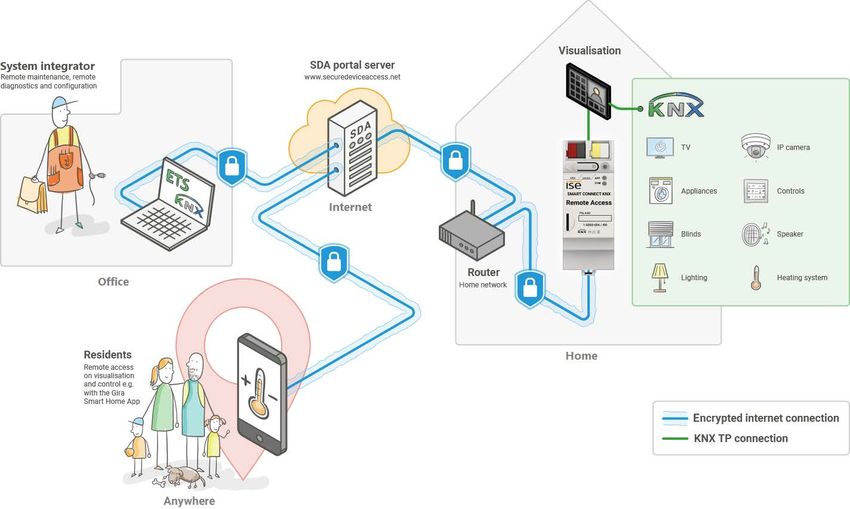
5.2 Data on device sticker
No. Description
1 Product name
2
2 Rated voltage
KNX 24VDC APP
COM 3 Individual address: Enter the assigned
individual address in the field with a per-
manent marker.
SMART CONNECT KNX
1 Muster 4 Index
Phy.Addr:
5 KNX Secure
3
0-000X-000 / I01 6 Installation method, here "S-mode"
9 4
TP S ; 7 Transfer medium, here "TP"
8 7 6 5 8 KNX certification
9 Order number
Figure 11: Device sticker
5.3 Top
The openings for securing the cover cap are located on the top of the device.
No. / Description
Index
1 Opening for securing the cover cap
2 Attached power connection terminal
3 Attached bus connection terminal
A Back of device
Figure 12: Top of device
SMART CONNECT KNX Remote Access 1-0003-004
© 2021 ise Individuelle Software und Elektronik GmbH p. 21 / 93Device design
5.4 Underside
No. Description
1 "Communication" LED
1 1 2 "Connection speed" LED
2 2 3 IP: 2x RJ45 (integrated switch)
3 3
Figure 13: Network connections
5.5 Device side
No. Description
1 Attached cover cap
2 Release lever for top-hat rail terminal
3 RJ45 cable (not included in the scope of supply) con-
nected to RJ45 socket.
Figure 14: Device side
SMART CONNECT KNX Remote Access 1-0003-004
© 2021 ise Individuelle Software und Elektronik GmbH p. 22 / 93Installation
6 Installation
6.1 Scope of supply
Figure 15: Scope of supply
No. Objects supplied Explanation
1 Device SMART CONNECT KNX Remote Access
2 Cover cap To protect connections from dangerous voltages.
3 Bus connection terminal To connect the KNX/TP bus lines.
4 Power connection terminal To connect the external power supply.
5 Installation instructions This product manual also provides you with the infor-
mation from the installation instructions but with addi-
tional details, application examples and configuration
instructions.
6 Sticker set Additional set of stickers with data for KNX Secure, ini-
tial device password and registration ID. The same
stickers are attached to the side of the device.
The installation instructions are part of the product.
Give these instructions to your customer.
SMART CONNECT KNX Remote Access 1-0003-004
© 2021 ise Individuelle Software und Elektronik GmbH p. 23 / 93Installation
6.2 Checking the installation conditions
Before starting with the mounting process, check that the requirements for the planned installation
environment have been met.
Important
Device functional fault due to incorrect ambient temperature in the installation environment
• Pay attention to the temperature of the installation environment: min. 0 °C to max. +45 °C.
• Do the not mount the SMART CONNECT KNX Remote Access above heat-emitting devices.
• Ensure that there is sufficient ventilation/cooling.
Pay attention to the device depth (see figure 16, item 1): DRA Plus, 74 mm.
1
Figure 16: Device depth
SMART CONNECT KNX Remote Access 1-0003-004
© 2021 ise Individuelle Software und Elektronik GmbH p. 24 / 93Installation
6.3 Mounting the device
Only qualified electricians may assemble and install the SMART CONNECT KNX Remote Access.
Specialist knowledge of the installation regulations is a prerequisite.
Warning
Danger from incorrect use
Incorrect use can result in damage to the device, fire or other dangers.
• Only qualified electricians may install and mount electrical devices.
• Follow the instructions in this product manual.
• This product manual is part of the product and must remain with the customer.
Warning
Danger of electric shock
An electric shock can result from touching live parts in the installation environment.
Electric shock can cause death.
Pay attention to the installation regulations:
• Route the KNX/TP bus line with the sheathing intact until it is close to the bus connection ter-
minal.
• Firmly press the bus KNX/TP bus line into the bus connection terminal as far as it will go.
• Install bus line leads without sheathing (SELV) reliably disconnected from all non-safety low-
voltage cables (SELV/PELV).
• Maintain the specified clearance.
• Attach the cover cap supplied.
• Also see also the VDE regulations governing SELV (DIN VDE 0100-410/"Safe separation",
KNX installation regulation) for more information.
SMART CONNECT KNX Remote Access 1-0003-004
© 2021 ise Individuelle Software und Elektronik GmbH p. 25 / 93Installation
Mounting and connecting the device
1. Snap the device vertically onto the top-hat rail (installation position: network connections at bot-
tom).
2. Connect the KNX/TP bus line (referred to below as the bus line) to the KNX connection of the
device (see figure 17, Pos. 1) by means of the supplied bus connection terminal (see figure 17,
Pos. 2). Polarity: left/red: “+”, right/black:
a. Attach the bus connection terminal (see figure 17, item 2).
b. Route the bus line with the sheathing intact until it is close to the bus connection terminal.
c. Firmly press the bus line into the bus connection terminal as far as possible.
d. Route the bus line to the back.
Figure 17: Connect the bus line
3. Connect the external power supply to the power supply terminal (see figure 18, Pos. 1) by means
of the supplied power connection terminal (see figure 18, Pos. 2). Polarity: left/yellow: “+”, right/
white: “–”.
a. Attach the power connection terminal (see figure 18, Pos. 2).
b. Route the power line with the sheathing intact until it is close to the power connection termi-
nal.
c. Firmly press the power line into the power connection terminal as far as possible.
d. Route the power supply line to the back.
Figure 18: Connect the power supply
SMART CONNECT KNX Remote Access 1-0003-004
© 2021 ise Individuelle Software und Elektronik GmbH p. 26 / 93Installation
Important
Functional fault in all devices due to incorrectly dimensioned power supply
The following applies if you use the non-choked auxiliary supply output of a KNX power supply
as an additional power supply:
The operating currents of all KNX/TP devices on the line section must not exceed the rated cur-
rent of the power supply.
4. Attach the cover cap supplied:
a. Route all cables to the back. The openings for fastening the cover cap (see figure 19, item 1)
must be clear. All cables must be between the openings.
Figure 19: Cable routing
b. Attach the cover cap over the connection terminals.
c. Press the cover cap together gently.
d. Insert the cover cap’s fastening claws into the openings until you feel the cover cap engage.
Figure 20: Attaching the cover cap
SMART CONNECT KNX Remote Access 1-0003-004
© 2021 ise Individuelle Software und Elektronik GmbH p. 27 / 93Installation
5. Connect the network:
a. Make sure that your network infrastructure (router, DNS server) is in operation.
b. The network connections are on the underside of the device.
c. Connect the IP network cable (RJ45 cable) to the device's network connection (RJ45 socket).
Figure 21: Connect the IP network cable
SMART CONNECT KNX Remote Access 1-0003-004
© 2021 ise Individuelle Software und Elektronik GmbH p. 28 / 93Device website
7 Device website
You can access the SMART CONNECT KNX Remote Access using the “Device website” application.
The device website offers the following functions among others:
• Check device state ► see Troubleshooting, p. 77.
• Configure network settings ► see Network settings via the device website, p. 43.
• Update firmware ► see Updating the firmware via the device website, p. 45.
• Reset to factory settings ► see Resetting the device to the factory settings via the device website,
p. 45.
• Generate log files ► see Generating log files, p. 78.
The device website is run on your installed browser. You do not require any additional software.
As soon as the device is available you can access the device website via the IP.
7.1 Device website: Calling up the start screen
Call up the device website by actioning one of the following:
• Enter the device’s IP address in the address bar of your browser.
• When you use the Microsoft Windows, select the device in the network environment in the category (see figure 22, Pos. 1): Double click on the device icon (see figure 22, item 2).
Figure 22: Accessing the device website via the network environment
The device website is password protected. The registration ID is also used as an
initial password after a factory reset. You can change the password in
after successful login.
SMART CONNECT KNX Remote Access 1-0003-004
© 2021 ise Individuelle Software und Elektronik GmbH p. 29 / 93Device website
7.2 Getting to know the interface of the device website
Figure 23: Device website start page
Item Element Function
1 Menu bar Call up other pages or run functions.
2 Page The page is shown.
3 Information Display of specific information.
4 Status bar Change language.
SMART CONNECT KNX Remote Access 1-0003-004
© 2021 ise Individuelle Software und Elektronik GmbH p. 30 / 93Device website
Menu Description
Device state Information:
• System information
• System configuration
• Application information
Functions:
• ► Change logging mode, p. 78
• Switch device to programming mode
Data logger Access to the data logger archive
System Functions:
• ► Configure network settings, p. 43
• ► Generate log files, p. 78
• Restart device
• ► Reset to factory settings, p. 43
• ► Update firmware, p. 45
Information:
• Disclaimer
• Licences
User • Changing the password
• Logging out from the device website
Table 4: Overview
After the SMART CONNECT KNX Remote Access is restarted, the connection sta-
tus with the SDA portal server will display incorrect values for a brief moment.
The web page will not be updated automatically. Use the refresh function in your
browser to do so.
SMART CONNECT KNX Remote Access 1-0003-004
© 2021 ise Individuelle Software und Elektronik GmbH p. 31 / 93Commissioning and configuration 8 Commissioning and configuration After installing the device and connecting the bus, power supply and network, the device can be com- missioned. 8.1 Quick start If you are already familiar with KNX and how to install KNX gateways, you can use this quick start to set up the SMART CONNECT KNX Remote Access for the first time. Logging onto the SDA portal 1. Register on the SDA portal https://securedeviceaccess.net. 2. Click on . 3. Enter registration ID (see enclosed sticker). 4. Add name and description for easier identification. Downloading the SDA client Not in the same network as the SMART CONNECT KNX Remote Access? Use the SDA client: 5. Access product page and scroll to the download section. 6. Download suitable SDA client for Windows (x86) or (x64). 7. Execute installation file to run on the same computer as the ETS. Connecting device via the SDA client 8. Start up SDA client in Windows start menu. 9. Log on with the same user data as for the SDA portal. 10. Select the SMART CONNECT KNX Remote Access in the selection list and connect. Incorporating the device into ETS 11. Click on the tab in the ETS. 12. Enter individual address. Individual address on delivery: 15.15.255. 13. Test input by clicking on . SMART CONNECT KNX Remote Access 1-0003-004 © 2021 ise Individuelle Software und Elektronik GmbH p. 32 / 93
Commissioning and configuration

8.2       Reading off the device status using the LEDs
The following status indicators (LEDs) can be found on the front panel.

   Figure 24: Status indicators (LEDs) on the front of the device

      No.                  Element                                        Description

      1           "Programming" LED (red)        Programming mode active/inactive display

      2           LED "APP" (green)              Serves as a status indicator for the application

      3           LED "COM" (yellow)             KNX/TP communication traffic display
   Table 5: Status indicators

The "Programming" LED shows independently of the operating mode whether the device is in program-
ming mode or not.

                  Colour                                            Description

        (Red, continuously        Programming mode is active.
      on)                         ► Assign individual address, S. 41

          (off)                   Programming mode is deactivated.
   Table 6: Status of the device – Programming mode

SMART CONNECT KNX Remote Access                                                                       1-0003-004
© 2021 ise Individuelle Software und Elektronik GmbH                                                    p. 33 / 93
Commissioning and configuration
The status indicators for the network are on the underside of the device.
Figure 25: Network LEDs
No. Element Description
1 "Connection speed" LED • LED lights up green: 100 Mbit/s
• LED is off: 10 Mbit/s (There is no connection if LED 2
also off. Check whether the cable is correctly con-
nected.)
2 "Communication" LED • LED lights up yellow-orange: Connected but currently no
telegram traffic
• LED flashes yellow-orange: Telegram traffic
3 IP connection 2x RJ45 (integrated switch)
Table 7: Device status – network
SMART CONNECT KNX Remote Access 1-0003-004
© 2021 ise Individuelle Software und Elektronik GmbH p. 34 / 93Commissioning and configuration
8.2.1 LEDs during device start-up
The "APP" and "COM" LEDs have different meanings depending on the phase in the operating mode. Af-
ter the power supply is switched on or after power returns, the device indicates its status using the fol-
lowing LED combinations:
APP COM Description
Correct operation
(off) (yellow) Device starting up.
(green) (yellow) Device booted up and ready for operation.
Error
(off) (off) No power supply.
• Check the connections and the power sup-
ply.
... ... ... ... (yellow) The device is fully started up but is not yet
(off)...(green)...(off)...(green)... configured. The system is configured S-
Slow flashing (about 1 Hz) mode.
• Configure the device in the ETS.
... ... ... ... (off) The device is fully started up but is not yet
(off)...(green)...(off)...(green)... configured. The system is configured S-
Slow flashing (about 1 Hz) mode.
• Configure the device in the ETS.
Connection to KNX is interrupted.
• Check whether the KNX and voltage con-
nections are mixed up.
• Check the bus connection.
• Check whether the power supply is cor-
rectly connected.
. . . . . (off) The firmware cannot be started.
(off).(green).(off).(green).(off).(green)
Rapid flashing • Contact support team.
... ... ... ... The newly loaded firmware cannot be started.
... ... ... ... The system is trying to activate the previous
(off)...(green)...(off)...(green)... firmware (invalid firmware).
(yellow)...(off)...(yellow)...(off)...
Slow flashing (about 1 Hz) in an alternating pattern • Contact support team.
Table 8: Device status – device starting up
SMART CONNECT KNX Remote Access 1-0003-004
© 2021 ise Individuelle Software und Elektronik GmbH p. 35 / 93Commissioning and configuration
8.2.2 LEDs in operation
LED status after successful device start-up:
APP Description
(green) The device is working perfectly (normal operation). The
portal access is generally allowed (group object 1). The
device connects to the SDA portal server but remote
access is not currently active. Redirects are possible.
(off) The device is currently starting up or is out of opera-
tion.
• Wait until the device start-up process is complete.
• If the device is still out of operation, check the con-
nections and the power supply.
… The portal access has been disabled via group object
A slow flash (about 1 Hz), 1. The device does not connect to the SDA portal
then 2 s pause server. Remote access is not possible due to technical
reasons.
… … … … … Remote access is allowed for at least one access
(green).(off).(green).(off).(green).(off) group or Quick Connect and there is at least one active
Three slow flashes (about 1 Hz), connection.
then 2 s pause
Table 9: "APP" LED in operation
COM Description
(yellow) The KNX connection has been established.
No KNX telegram traffic.
The LED is also deemed to be continuously on if brief
irregular interruptions occur.
. . . . . KNX connection has been established.
(off).(yellow).(off).(yellow).(off).(yellow). KNX telegram traffic.
Rapid flashing
Error
(off) Connection to KNX is interrupted.
• Check whether the KNX and voltage connections
are mixed up.
• Check the bus connection.
• Check whether the power supply is correctly con-
nected.
Table 10: "COM" LED in operation
SMART CONNECT KNX Remote Access 1-0003-004
© 2021 ise Individuelle Software und Elektronik GmbH p. 36 / 93Commissioning and configuration
8.3 Configuration
The device is configured in the ETS (Engineering Tool Software). The ETS is available with a different
range of functions from the KNX Association (www.knx.org).
All descriptions in this documentation on configuration in the ETS refer to the ETS Professional version
5.
Help on the ETS is available in the integrated ETS Online Help.
• Press the [F1] button.
Note:
The SMART CONNECT KNX Remote Access is configured as follows when delivered
and after a factory reset:
• Remote access is activated for the Residents and Installers access groups and for
Quick Connect.
• The individual address for the device is 15.15.255. The address for the three other
three individual interfaces (tunnelling server) is 15.15.254.
Work steps
1. Add the SMART CONNECT KNX Remote Access as a device in the ETS, ► see Creating the device
in the ETS, p. 38.
2. Assign an individual address to the device in the ETS and up to three individual interface
addresses in accordance with the KNX topology.
3. Select the option or select
and complete the following fields: IP address, IP subnet mask and standard gateway address, ►
see Setting the IP address, IP subnet mask and standard gateway address, p. 40.
4. Set the general parameters, ► see Configuring parameters, p. 51.
5. Link the group addresses to the group objects.
6. The SMART CONNECT KNX Remote Access is now ready for commissioning using > and for functions testing.
Note:
We recommend downloading via the direct IP connection due to the significantly
shorter transfer times. Select the tab → →
→ on the ETS start page.
SMART CONNECT KNX Remote Access 1-0003-004
© 2021 ise Individuelle Software und Elektronik GmbH p. 37 / 93Commissioning and configuration
8.3.1 Creating the device in the ETS
Depending on whether the product database entry already exists in the ETS catalogue or whether the
device is already being used in your existing project, different work steps are required in order to use the
current version.
Work steps
Device already exists in the ETS catalogue?
Yes No
Update product database. Importing product database entry
During an update, the old product database There are numerous possibilities for importing
entry is replaced by the new one. a new product database entry. Below we will
assume that you have downloaded the product
database entry yourself.
► see Importing a new product database
entry, p. 38.
Device in existing project should be updated?
Yes No
You must update the device properly so that Add the device to your topology in the usual
the existing links to group addresses are main- way.
tained.
► see Updating a product in the existing pro-
ject, p. 39.
Table 11: Work steps – creating the device in the ETS
Importing a new product database entry
Requirement: You have now downloaded the product database entry (product file) from our website at
www.ise.de.
1. Start the ETS and select the tab on the Start page.
2. Select the button in the toolbar.
3. In the window, open the product file and press on the button to
confirm your selection.
4. Follow the further instructions in the ETS. If necessary, call up the Online Help with the [F1] button.
SMART CONNECT KNX Remote Access 1-0003-004
© 2021 ise Individuelle Software und Elektronik GmbH p. 38 / 93You can also read