EE 346 Microprocessor Principles and Applications An Introduction to Microcontrollers, Assembly Language, and Embedded Systems - CSULB
←
→
Page content transcription
If your browser does not render page correctly, please read the page content below
EE 346 Microprocessor Principles and Applications

An Introduction to Microcontrollers, Assembly Language, and Embedded Systems

                                                                               1|P a g e
An Introduction to Microcontrollers, Assembly Language, and Embedded Systems

                                                     READING

The AVR Microcontroller and Embedded Systems using Assembly and C) by Muhammad Ali Mazidi, Sarmad Naimi, and Sepehr Naimi

Chapter 0: Introduction To Computing
       Section 0.1: Number Systems and Appendix A “Number Systems” at the end of this document
       Section 0.2: Digital Primer
Chapter 1: The AVR Microcontroller: History and Features
       Section 1.1: Microcontrollers and Embedded Processors
Chapter 2: AVR Architecture and Assembly Language Programming
       Section 2.5: AVR Data Format and Directives
       Section 2.6: Introduction to AVR Assembly Programming
       Section 2.7: Assembling An AVR Program

                                                                                                                     2|P a g e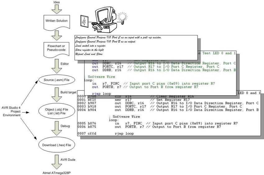
An Introduction to Microcontrollers, Assembly Language, and Embedded Systems

                                                                                                        CONTENTS

Reading .......................................................................................................................................................................................................................... 2
What is an Embedded System? .................................................................................................................................................................................... 4
The Building Blocks of an Embedded System............................................................................................................................................................... 5
What is an Arduino? ...................................................................................................................................................................................................... 6
What is 3DoT? ............................................................................................................................................................................................................... 7
What is The 3DoT Maze Kit? ......................................................................................................................................................................................... 8
What is a Program? ....................................................................................................................................................................................................... 9
How is Machine Code Related to Assembly Language?............................................................................................................................................. 10
Anatomy of an Assembly Instruction ......................................................................................................................................................................... 11
Design Example ........................................................................................................................................................................................................... 12
Development Steps ..................................................................................................................................................................................................... 13
Help .............................................................................................................................................................................................................................. 14

                                                                                                                                                                                                                     3|P a g e
An Introduction to Microcontrollers, Assembly Language, and Embedded Systems
                                        WHAT IS AN EMBEDDED SYSTEM?

• An embedded system is an electronic system
   that contains at least one controlling device,
   i.e. “the brain”, but in such a way that it is
   hidden from the end user. That is, the
   controller is embedded so far in the system
   that usually users don’t realize its presence.

• Embedded systems perform a dedicated
   function.

What is the Controlling Device?
EE Course      Technology                                       Tools

EE201          Discrete Logic                                   Boolean Algebra

EE301          Field Programmable Gate Array (FPGA),            HDL (typically VHDL or Verilog)
               Application-Specific Integrated Circuit (ASIC)

EE346          Microcontroller                                  Program (typically C++ or Assembly)

EE443          System on a Chip (SoC)                           System Level Design Language

                                                                                                      4|P a g e
An Introduction to Microcontrollers, Assembly Language, and Embedded Systems
                             THE BUILDING BLOCKS OF AN EMBEDDED SYSTEM
“This course will be an introduction to modern RISC based microcontrollers and assembly language programming.
We will use the Atmel AVR family of microcontrollers to teach hardware design of small, minimum-component
systems performing simple task-oriented activities.” Source: EE346 Syllabus

                                                                                                    5|P a g e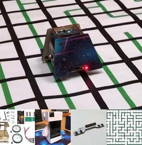
An Introduction to Microcontrollers, Assembly Language, and Embedded Systems

                                                  WHAT IS AN ARDUINO?

•   Arduino is an open-source electronics PCB containing a microcontroller and the things needed to support it: Power Supply,
    Communications, Reset Button, Clock, and Connectors for adding Sensors and Actuators in the physical world.

•   Using an Arduino you can develop interactive objects, taking inputs from a variety of
    switches or sensors, and controlling a variety of lights, motors, and other physical outputs.

•   The Arduino consists of two parts; the hardware and the software.

       o Our Robot Board is based on the Arduino Leonardo which contains an ATmega32U4
           8 bit microcontroller.

       o We will be using AVR Studio to develop the software for the Arduino in place of the
           Arduino IDE and associated Scripting Language.

                                                                                                                      6|P a g e
WHAT IS 3DOT

3DoT (The 3D of Things) is a micro-footprint 3.5 x 7 cm all-in-one Arduino compatible microcontroller board
designed for robot projects by Humans for Robots.
   •   Microcontroller: ATmega32U4
   •   Bluetooth: FCC-certified BLE 5.0 module
   •   Power Management:
          •  RCR123A battery holder
         •   Included 600 mAh rechargeable battery
         •   Microchip MCP7383 battery charge controller
         •   External battery connector – for input voltages
             between 4 – 18 V
         •   Reverse polarity protection – plug in the
             battery backwards? No problem
   •   Motors & Servos:
        •   2x JST motor connectors
         •   2x standard servo connectors
   •   Expansion:
         •  16-pin top female headers for shields – providing I/O, I²C, SPI, USART, 3.3 V and 5 V.
         •   Forward-facing 8-pin female header for sensor shields – providing 4 analog pins, I²C, and 3.3 V power
             – for sensor shields like infrared or metal-detecting shields. Great location for headlights, lasers,
             ultrasonics, etc.
   •   Programming switch: Three-position switch for easy programming
         •   No more double-tapping a button and rushing to program your board, or your robot trying to drive
             away while programming. Set the switch to PRG to program, RUN to execute your code.
                                                                                                          7|P a g e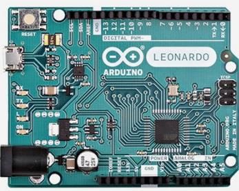
WHAT IS THE 3DOT MAZE KIT?

  Designed by Humans for Robots for CSULB EE Digital Design and Project courses, the 3DoT Maze
  Kit includes almost everything needed to
  complete the Labs.
K IT C ONTENTS
       • 3DoT PaperBot Chassis
            o 3DoT Board v10.1
            o Bluetooth LE module
            o Wood Chassis
            o Drivetrain (motors, wheels,
               caster)
       • IR Sensor Shield
       • (soldered)
       • Wheel Rotary Encoder Shield
       • 3x4 ft Maze (Back/White, Color
         based on cost)
N OT INCLUDED
      • PaperBot Template (Free Download)
      • USB-B cable
      • Playing Cards (Free Download)

                                                                                       8|P a g e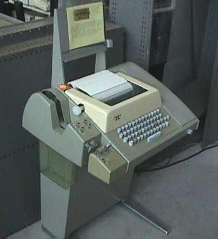
WHAT IS A PROGRAM?
• The Program is a “very specific list of instructions” to the computer.

• The process of “creating the program” is where much of an electrical engineer’s time is spent.

• The program is often referred to as
   Software, while the physical system
   components are called Hardware. Software
   held within non-volatile memory is called
   Firmware.

• Software design is all about creating
   patterns of 0’s and 1’s in order to get the
   computer to do what we want. These 0's
   and 1's are known as Machine Code.

   0010 0111 0000 0000 → 1110 1111 0001 1111 → 1011 1001 0000 0111 → 1011 1001 0001 1000
   1011 1001 0000 0100 → 1011 0000 0111 0110 → 1011 1000 0111 0101 → 1100 1111 1111 1101

• The architecture of the processer (or computer) within a microcontroller is unique as are the Machine Code
   Instructions it understands.
   0010 0111 0000 0000
   1110 1111 0001 1111

• The list of Machine Code Instructions understood by a Microcontroller is known as the Machine Language.

                                                                                                    9|P a g e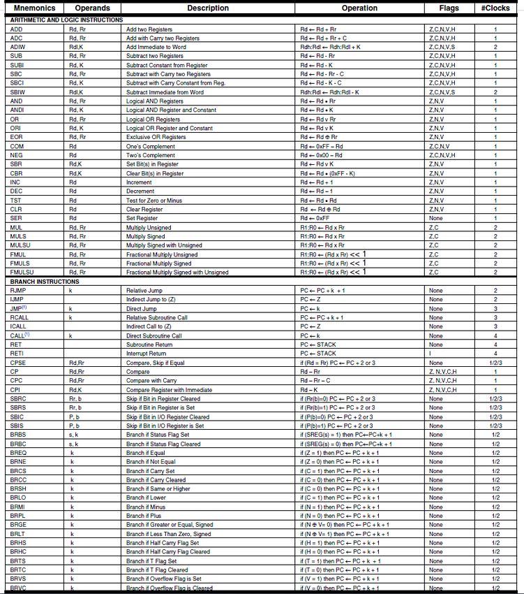
HOW IS MACHINE CODE RELATED TO ASSEMBLY LANGUAGE?

Machine Code (The language of the machine)
   • Binary Code (bit sequence) that directs the computer to carry
      out (execute) a pre-defined operation.
      0010   0111   0000   0000
      1110   1111   0001   1111
      1011   1001   0000   0111
      1011   1001   0001   1000
Assembly Language
   • A computer language where there is a one-to-one
      correspondence between a symbolic (assembly language
      instruction) and a machine code instruction.

   • The language of the machine in human readable form
      clr   r16
      ser   r17
      out   DDRC, r16
      out   PORTC, r17

Corollary
   • Specific to a single computer or class of computers (non-portable)

                                                                             10 | P a g e
ANATOMY OF AN ASSEMBLY INSTRUCTION
Sample Code Segment
Machine Code Assembly Code
Binary Hex
0010 0111 0000 0000 0x2700 clr r16
1110 1111 0001 1111 0xEF1F ser r17
1011 1001 0000 0111 0xB907 out DDRC, r16
1011 1001 0001 1000 0xB918 out PORTC, r17
• The Operation Code or Opcode for short, is a mnemonic that tells the CPU what instruction is to be
executed. In the sample code above that would be clr (clear), ser (set register), and out (output to
I/O location). One or more operands follow the Opcode.
• The Operand(s) specify the location of the data that is to be operated on by the CPU. In many cases it is
the Arithmetic Logic Unit (ALU) that performs the specified operation.
11 | P a g eDESIGN EXAMPLE
Write an Assembly Program to turn a light on and off with a switch. A similar program was used in
the design of The Wake-up Machine.
12 | P a g eDEVELOPMENT STEPS
13 | P a g eHELP
0010 0111 0000 0000 2 = 2700 16 = clr r16...
An Important part of this course is understanding the Design and Language of "The Computer."
The computer implements the classical digital gate you learned in your Digital Logic class (EE201) in software with
instructions like and, or, and eor.
You are also going to have to seamlessly move from binary to hexadecimal and back again (i.e., Number Systems).
Computer programs move data through Registers, so a working knowledge of Flip-Flops and Registers is also an
important foundational part of this class.
Finally, instead of designing with gates (EE201) you will be designing with code. So you will need to review
Programming concepts like: data transfer (assignment expressions) , arithmetic and logic operators, control
transfer (branching and looping), and bit and bit test operators that you leaned in your programming class
(CECS174 or CECS100).
The good news is that help is available in Chapter 0: “Introduction to Computing” of your textbook, the
supplemental reading provided at the beginning of this document, the web, and Appendix A - Number Systems.
14 | P a g eAPPENDIX A – NUMBER SYSTEMS
Numbers and Their Computer Representation
INTRODUCTION
Base 10 result of ten fingers
Arabic symbols 0-9, India created Zero and Positional Notation
Other Systems: Roman Numerals: essentially additive, Importance of Roman Numeral lies in whether a symbol precedes or follows another
symbol. Ex. IV = 4 versus VI = 6. This was a very clumsy system for arithmetic operations.
POSITIONAL NOTATION (POSITIVE REAL INTEGERS)
Fractional numbers will not be considered but it should be noted that the addition of said would be a simple and logical addition to the theory presented.
The value of each digit is determined by its position. Note pronunciation of 256 “Two Hundred and Fifty Six?
Ex. 256 = 2*102 + 5*101 + 6*100
Generalization to any base or radix
Base or Radix = Number of different digit which can occur in each position in the number system.
N = Anrn + An-1rn-1 + … + A1r1 + A0r0 (or simple A1r + A0)
INTRODUCTION TO BINARY SYSTEM
The operation of most digital devices is binary by nature, either they are on or off.
Examples: Switch, Relay, Tube, Transistor, and TTL IC
Thus it is only logical for a digital computer to in base 2.
Note: Future devices may not have this characteristic, and this is one of the reasons the basics and theory are important. For they add flexibility
to the system.
In the Binary system there are only 2 states allowed; 0 and 1 (FALSE or TRUE, OFF or ON)
15 | P a g eExample: Most Significant Bit
High Order Bit
1010 = 1*23 + 0*22 + 1*21 + 0*20 = 1010
Least Significant Bit Denotes Base 10
Low Order Bit Usually implied by context
Bit = One Binary Digit (0 or 1)
This positional related equation also gives us a tool for converting from a given radix to base 10 - in this example Binary to Decimal.
BASE EIGHT AND BASE SIXTEEN
Early in the development of the digital computer Von Neuman realized the usefulness of operating in intermediate base systems such as base
8 (or Octal)
By grouping 3 binary digits or bits one octal digit is formed. Note that 23 = 8
Binary to Octal Conversion Table
222120
000 = 0
001 = 1
010 = 2
011 = 3
100 = 4
101 = 5
110 = 6
111 = 7 Symbols (not numbers) 8 and 9 are not used in octal.
Example: 100 001 010 110
4 1 2 6 8 = 4*83 + 1*82 + 2*81 + 6*80 = 2134
This is another effective way of going from base 2 to base 10
Summary: Base 8 allows you to work in the language of the computer without dealing with large numbers of ones and zeros. This is made
possible through the simplicity of conversion from base 8 to base 2 and back again.
In microcomputers groupings of 4 bits (as opposed to 3 bits) or base 16 (24) is used. Originally pronounced Sexadecimal, base 16 was quickly
renamed Hexadecimal (this really should be base 6).
16 | P a g eBinary to Hex Conversion Table
23222120
0000 = 0
0001 = 1
0010 = 2
0011 = 3
0100 = 4
0101 = 5
0110 = 6
0111 = 7
1000 = 8
1001 = 9
1010 = A
1011 = B
1100 = C
1101 = D
1110 = E
1111 = F
In Hex Symbols for 10 to 15 are borrowed from the alphabet. This shows how relative numbers really are or in other words, they truly are just
symbols.
Example: 1000 0101 0110
8 5 6 16 = 8*162 + 5*161 + 6*160 = 2134
It is not as hard to work in base 16 as you might think, although it does take a little practice.
CONVERSION FROM BASE 10 TO A GIVEN RADIX (OR BASE)
Successive Division is best demonstrated by an example
2 43 \
2 21 \ 1 Least Significant Bit
2 10 \ 1
2 5 \ 0
2 2 \ 1
2 1 \ 0
0 1 Most Significant Bit
To get the digits in the right order let them fall to the right.
For this example: 4310 = 1010112 Quick Check (Octal) 101 011 = 5*8 + 3 = 4310
17 | P a g eAnother example: Convert 4310 from decimal to Octal
8 43 \
8 5 \ 3
0 5 Most Significant Bit
For this example: 4310 = 538 Quick Check (Octal) 5*8 + 3 = 4310
GENERALIZATION OF THE PROCEDURE OR WHY IT WORKS
r N \
r N1 \ A0 Least Significant Bit
r N2 \ A1
r N3 \ A2
A3
r Nn-1 \
r Nn \ An-1
0 An Most Significant Bit
Where r = radix, N = number, A = remainder, and n = the number of digits in radix r for number N. Division is normally done in base 10.
Another way of expressing the above table is:
N = r*N1 + A0
N1 = r*N2 + A1
N2 = r*N3 + A2
Nn-1 = r*Nn + An-1
Nn = r*0 + An
or (now for the slight of hand)
N = r*( r*N2 + A1)+ A0 substitute N1
N = r2N2 + rA1+ A0 multiply r through equation
N = r2(r*N3 + A2) + rA1+ A0 substitute N2
N = Anrn + An-1rn-1 + … + A1r1 + A0r0
18 | P a g eNOMENCLATURE
Bit = 1 binary digit
Byte = 8 bits
Nibble = one half byte = 4 bits
Word = Computer Dependent
Binary Arithmetic
BINARY ADDITION
Binary addition is performed similar to decimal addition using the following binary addition rules:
0+0=0
0+1=1
1+0=1
1 + 1 = 10 (0 with a carry of 1)
Examples:
Problem 2110 + 1010 = 3110 4510 + 5410 = 9910 310 + 710 = 1010
101012 1011012 0112
+ 010102 + 1101102 + 1112
_________________ _________________ _________________
111112 11000112 10102
Check 1*23 + 0*22 + 1*21 + 0*20
1*8 + 0*4 + 1*2 + 0*1 = 1010
19 | P a g eOCTAL ADDITION
Octal addition is also performed similar to decimal addition except that each digit has a range of 0 to 7 instead of 0 to 9.
Problem 2110 + 1010 = 3110 4510 + 5410 = 9910 310 + 710 = 1010
258 558 38
+ 128 + 668 + 78
_________________ _________________ _________________
378 1438 128
Check 3*81 + 7*80 1*82 + 4*81 + 3*80 1*81 + 2*80
3*8 + 7*1 = 3110 64 + 32 + 3 = 9910 8 + 2 = 1010
HEXADECIMAL ADDITION
Hex addition is also performed similar to decimal addition except that each digit has a range of 0 to 15 instead of 0 to 9.
Problem 2110 + 1010 = 3110 4510 + 5410 = 9910 310 + 710 = 1010
1516 2D16 316
+ 0A16 + 3616 + 716
_________________ _________________ _________________
1F16
6316 A16 (not 10)
Check 1*161 + 15*160 6*161 + 3*160 10*160
16 + 15 = 3110 96 + 3 = 9910 1010
20 | P a g eBINARY MULTIPLICATION
Decimal Binary
1110 10112
x 1310 x 11012
_________________ _________________
3310 10112
00002
1110
10112
_________________
10112
14310 _________________
100011112
Check 8*161 + 15*160
128 + 15 = 14310
BINARY DIVISION
Decimal Binary
2110 101012
510 10510 1012 11010012
10 101
05 110
05 101
00 101
101
000
Check 1*161 + 5*160
16 + 5 = 2110
Practice arithmetic operations by making problems up and then checking your answers by converting them back to base 10 via different bases
(i.e., 2, 8, and 16).
21 | P a g eHow a computer performs arithmetic operations is a much more involved subject and has not been dealt with in this section.
COMPLEMENTS AND NEGATIVE NUMBERS OR ADDING A SIGN BIT
Addition, Multiplication, and Division is nice but what about subtraction and negative numbers? From grade school you have learned that
subtraction is simply the addition of a negative number. Mathematicians along with engineers have exploited this principle along with modulo
arithmetic — a natural outgrowth of adders of finite width — to allow computers to operate on negative numbers without adding any new
hardware elements to the arithmetic logic unit (ALU).
SIGN MAGNITUDE
Here is a simple solution, just add a sign bit. To implement this solution in hardware you will need to create a subtractor; which means more
money.
sign magnitude
Example: -2 = 1 00102
ONES COMPLEMENT
Here is a solution that is a little more complex. Add the sign bit and invert each bit making up the magnitude — simply change the 1’s to 0’s and
the 0’s to 1’s.
sign magnitude
Example: -2 = 1 11012
To subtract in 1’s complement you simply add the sign and magnitude bits letting the last carry bit (from the sign) fall into the bit bucket, and
then add 1 to the answer. Once again let the last carry bit fall into the bit bucket. The bit bucket is possible due to the physical size of the adder.
0 10102 10
+ 1 11012 +(-2)
___________________ ____________
0 10002 8
+ 12 Adjustment
___________________
0 10012
Although you can now use your hardware adder to subtract numbers, you now need to add 1 to the answer. This again means adding hardware.
Compounding this problem, ones complement allows two numbers to equal 0 (schizophrenic zero).
22 | P a g eTWOS COMPLEMENT
Here is a solution that is a little more complex to set up, but needs no adjustments at the end of the addition. There are two ways to take the
twos complement of a number.
Method 1 = Take the 1’s complement and add 1
0 00102 2 start
___________________ ____________
+ 1 11012 1’s complement (i.e. invert)
+ 12 add 1
___________________
1 11102
Method 2 = Move from right to left until a 1 is encountered then invert.
0 00102 start 210
02 no change
102 no change but one is encountered
1102 invert change 0 to 1
11102 invert change 0 to 1
1 11102 invert change 0 to 1
Subtraction in twos complement is the same as addition. No adjustment is needed, and twos complement has no schizophrenic zero although
it does have an additional negative number (see How It Works).
0 10102 10
+ 1 11102 +(-2)
___________________ ____________
0 10012 8
23 | P a g eExamples:
Problem 3310 - 1910 = 1410 6910 - 8410 = -1510
0 1000012 0 10001012
+ 1 1011012 + 1 01011002
_________________ _________________
0 0011102 1 11100012
Check convert to convert back to sign magnitude
intermediate base - 00011112
E16 = 1410 convert to intermediate base (16)
- F16 = - 1510
WHY IT WORKS
Real adders have a finite number of bits, which leads naturally to modulo arithmetic — the bit bucket.
OVERFLOW
With arithmetic now reduced to going around in circles, positive numbers can add up to negative and vice-versa. Two tests provide a quick
check on whether or not an “Overflow” condition exists.
Test 1 = If the two numbers are negative and the answer is positive, an overflow has occurred.
Test 2 = If the two number are positive and the answer is negative, an overflow has occurred.
24 | P a g eIf computers were calculators and the world was a perfect place, we would be done. But they are not and so we continue by looking at a few real world
problems and their solutions.
CHARACTER CODES OR NON-NUMERIC INFORMATION
DECIMAL NUMBER PROBLEM
Represent a Decimal Numbers in a Binary Computer. A binary representation of a decimal number, a few years ago, might have been “hard
wired” into the arithmetic logic unit (ALU) of the computer. Today it, more likely than not, is simply representing some information that is naturally
represented in base 10, for example your student ID.
SOLUTION
In this problem, ten different digits need to be represented. Using 4 bits 24 or 16 combinations can be created. Using 3 bits 23 or 8 combinations
can be created. Thus 4 bits will be required to represent one Decimal Digit. It should here be pointed out how 16 combinations can be created
from 4 bits (0000 - 1111) while the largest numeric value that can be represented is 15. The reason that the highest numeric value and the
number of combinations are different, is due to zero (0) being one of the combinations. This difference points up the need to always keep track
of wetter or not you are working zero or one relative and what exactly you are after — a binary number or combinations.
The most common way of representing a decimal number is named Binary Coded Decimal (BCD). Here each binary number corresponds to
its decimal equivalent, with numbers larger than 9 simply not allowed. BCD is also known as an 8-4-2-1 code since each number represents the
respective weights of the binary digits. In contrast the Excess-3 code is an unweighted code used in earlier computers. Its code assignment
comes from the corresponding BCD code plus 3. The Excess-3 code had the advantage that by complementing each digit of the binary code
representation of a decimal digit (1’s complement), the 9’s complement of that digit would be formed. The following table lists each decimal digit
and its BCD and Excess-3 code equivalent representation. I have also included the negative equivalent of each decimal digit encoded using the
Excess-3 code. For instance, the complement of 0100 (1 decimal) is 1011, which is 8 decimal. You can find more decimal codes on page 18 of
“Digital Design” by M. Morris Mano (course text).
Binary Coded Excess-3
Decimal (BCD)
Decimal Binary Decimal Binary 9’s
Digit Code Digit Code Compliment
8-4-2-1
0 0000 N/A 0000 1111
1 0001 N/A 0001 1110
2 0010 N/A 0010 1101
3 0011 0 0011 1100
4 0100 1 0100 1011
25 | P a g e5 0101 2 0101 1010
6 0110 3 0110 1001
7 0111 4 0111 1000
8 1000 5 1000 0111
9 1001 6 1001 0110
N/A 1010 7 1010 0101
N/A 1011 8 1011 0100
N/A 1100 9 1100 0011
N/A 1101 N/A 1101 0010
N/A 1110 N/A 1110 0001
N/A 1111 N/A 1111 0000
ALPHANUMERIC CHARACTER PROBLEM
Represent Alphanumeric data (lower and upper case letters of the alphabet (a-z, A-Z), digital numbers (0-9), and special symbols (carriage
return, line feed, period, etc.).
SOLUTION
To represent the upper and lower case letters of the alphabet, plus ten numbers, you need at least 62 (2x26+10) unique combinations.
Although a code using only six binary digits providing 26 or 64 unique combinations would work, only 2 combinations would be left for special
symbols. On the other hand a code using 7 bits provides 27 or 128 combinations, which provides more than enough room for the alphabet,
numbers, and special symbols. So who decides which binary combinations correspond to what character. Here there is no “best way.” About
thirty years ago IBM came out with a new series of computers which used 8 bits to store one character (28 = 256 combinations), and devised
the Extended Binary-Coded Decimal Interchange Code (EBCDIC pronounced ep-su-dec) for this purpose. Since IBM had a near monopoly
on the computer field, at that time, the other computer makers refused to adopt EBCDIC, and that is how the 7bit American Standard Code for
Information Interchange (ASCII) came into existence. ASCII has now been adopted by virtually all micro-computer and mini-computer
manufacturers. The table below shows a partial list of the ASCII code. Page 23 of the text lists all 128 codes with explanations of the control
characters.
DEC HEX CHAR DEC HEX CHAR
32 20 64 40 @
33 21 ! 65 41 A
34 22 “ 66 42 B
35 23 # 67 43 C
36 24 $ 68 44 D
37 25 % 69 45 E
38 26 & 70 46 F
39 27 ‘ 71 47 G
40 28 ( 72 48 H
26 | P a g e41 29 ) 73 49 I
42 2A * 74 4A J
43 2B + 75 4B K
44 2C , 76 4C L
45 2D - 77 4D M
46 2E * 78 4E N
47 2F / 79 4F O
48 30 0 80 50 P
49 31 1 81 51 Q
50 32 2 82 52 R
51 33 3 83 53 S
52 34 4 84 54 T
53 35 5 85 55 U
54 36 6 86 56 V
55 37 7 87 57 W
56 38 8 88 58 X
57 39 9 89 59 Y
58 3A : 90 5A Z
59 3B ; 91 5B [
60 3C < 92 5C \
61 3D = 93 5D ]
62 3E > 94 5E ^
63 3F ? 95 5F _
The word “string” is commonly used to describe a sequence of characters stored via their numeric codes — like ASCII).
Although ASCII requires only 7 bits, the standard in computers is to use 8 bits, where the leftmost bit is set to 0. This allows you to code
another 128 characters (including such things as Greek letters), giving you an extended character set, simply by letting the leftmost bit be a 1.
This can also lead to a computer version of the tower of Babel. Alternatively, the leftmost bit can be used for detecting errors when transmitting
characters over a telephone line. Which brings us to our next problem.
SYNTHESIS
Although ASCII solves the communication problem between English speaking computers, what about Japanese, Chinese, or Russian
computers which have different, and in all these examples, larger alphabets?
COMMUNICATION PROBLEM
Binary information may be transmitted serially (one bit at a time) through some form of communication medium such as a telephone line or a
radio wave. Any external noise introduced into the medium can change bit values from 1 to 0 or visa versa.
27 | P a g eSOLUTION
The simplest and most common solution to the communication problem involves adding a parity bit to the information being sent. The function
of the parity bit is to make the total number of 1’s being sent either odd (odd parity) or even (even parity). Thus, if any odd number of 1’s were
sent but an even number of 1’s received, you know an error has occurred. The table below illustrates the appropriate parity bit (odd and even)
that would be appended to a 4-bit chunk of data.
SYNTHESIS
What happens if two binary digits change bit values? Can a system be devised to not only detect errors but to identify and correct the bit(s) that
have changed? One of the most common error-correcting codes was developed by R.W. Hamming. His solution, known as a Hamming code,
can be found in a very diverse set of places from a Random Access Memory (RAM) circuit to a Spacecraft telecommunications link. For more
of error correcting codes read pages 299 to 302 of the text.
Although detecting errors is nice, preventing them from occurring is even better. Which of course brings us to our next problem.
SHAFT ENCODER PROBLEM
As a shaft turns, you need to convert its radial position into a binary coded digital number.
SOLUTION
The type of coder which will be briefly described below converts a shaft position to a binary-coded digital number. A number of different types
of devices will perform this conversion; the type described is representative of the devices now in use, and it should be realized that more
complicated coders may yield additional accuracy. Also, it is generally possible to convert a physical position into an electric analog-type signal
and then convert this signal to a digital system. In general, though, more direct and accurate coders can be constructed by eliminating the
intermediate step of converting a physical position to an analog electric signal. The Figure below illustrates a coded-segment disk which is
coupled to the shaft.
28 | P a g eThe shaft encoder can be physically realized using electro-mechanical (brush) or electro-optical technology. Assuming an electro-optical
solution, the coder disk is constructed with bands divided into transparent segments (the shaded areas) and opaque segments (the unshaded
areas). A light source is put on one side of the disk, and a set of four photoelectric cells on the other side, arranged so that one cell is behind
each band of the coder disk. If a transparent segment is between the light source and a light-sensitive cell, a 1 output will result; and if an opaque
area is in front of the photoelectric cell, there will be a O output.
There is one basic difficulty with the coder illustrated: if the disk is in a position where the output number is changing from 011 to 100, or in any
position where several bits are changing value, the output signal may become ambiguous. As with any physically realized device, no matter
how carefully it is made, the coder will have erroneous outputs in several positions. If this occurs when 011 is changing to 100, several errors
are possible; the value may be read as 111 or 000, either of which is a value with considerable errors. To circumvent this difficulty, engineers
use a "Gray," or "unit distance," code to form the coder disk (see previous Figure). In this code, 2 bits never change value in successive coded
binary numbers. Using a Gray coded disk, a 6 may be read as 7, or a 4 as 5, but larger errors will not be made. The Table below shows a listing
of a 4-bit Gray code.
Decimal Gray Code
0 0000
1 0001
2 0011
3 0010
4 0110
5 0111
6 0101
7 0100
8 1100
9 1101
10 1111
11 1110
12 1010
13 1011
14 1001
15 1000
SYNTHESIS
Gray code is used in a multitude of application other than shaft encoders. For example, CMOS circuits draw the most current when they are
switching. If a large number of circuits switch at the same time unwelcome phenomena such as “Ground Bounce” and “EMI Noise” can result.
If the transistors are switching due to some sequential phenomena (like counting), then these unwelcome visitors can be minimized by replacing
a weighted binary code by a Gray code.
29 | P a g eIf the inputs to a binary machine are from an encoder using a Gray code, each word must be converted to conventional binary or binary-coded
decimal bit equivalent. How can this be done? Before you can answer this question, you will need to learn about Boolean Algebra — what a
coincidence, that’s the topic of the next Section.
30 | P a g eAPPENDIX B – ATMEGA INSTRUCTION SET1
1
Source: ATmega328P Data Sheet http://www.atmel.com/dyn/resources/prod_documents/8161S.pdf Chapter 31 Instruction Set Summary
31 | P a g e32 | P a g e
33 | P a g e
You can also read