Effect of Ploughing Speed on Stress Development on the Steyr Tractor Lift System
←
→
Page content transcription
If your browser does not render page correctly, please read the page content below
1

Effect of Ploughing Speed on Stress Development on the Steyr Tractor Lift System
        on Clay Loam Soil Of Bauchi-Nigeria in the Northern Guinea Savannah

                       Sule Samuel1, M. G. Yisa2 an C. N Ohanwe1,

                              1. Agricultural Engineering Technology Department
                                       Federal Polytechnic, Bauchi.
                                           Bauchi State-Nigeria
                                         Sulesamuel@yahoo.co.uk

                                    2. Agricultural Engineering Department
                                  Federal University of Technology, Minna
                                                Niger State-Nigeria

                                                ABSTRACT
    Otmianowski, (1983) stated that all agricultural machines that work on the farm are exposed to
    the dynamic effect of undulating terrain as well as rolling friction on both loose soil and bed-like
    farmland. These and other factors all contribute to the development of stress on the agricultural
    machine elements which may either lead to breakdowns or failures of some parts. As part of an
    effort to investigate into the frequent failures of the Steyr tractor lift system, the effects of
    ploughing speed on the development of stress on the Steyr tractor lift system (stabilizers and
    brackets) on a clay loam soil of Bauchi-Nigeria in the Northern Guinea Savannah were
    investigated using quarter-bridge strain gauge circuit with temperature compensation. It was
    found that stress on these parts of the three-point linkage system increased with increase in speed
    of ploughing. The average stress values obtained were relatively higher when compared with the
    yield point stress (0.23kN/mm2) of bracket material. The use of a spring loaded ‘U’ bolt was
    found to reduce the stress.

    Keywords: Ploughing, speed, stress, strain gauge, stabilizers, Nigeria.

                                          1. INTRODUCTION
    The three-point lift system is made up of the upper link, the right lower link and the left lower
    link. Fig.1 shows the connections in the Steyr tractor lift system. Barger et al (1963) stated that
    as with most other design problems, one best hitch system does not exist, but perhaps for a
    specific application.

    Khurmi and Gupta (2002) stated that machine parts are subjected to various forces which may be
    due to either energy transmitted by the weight of machine, frictional resistances, inertia of
    reciprocating parts or change of temperature and lack of balance of moving parts. The different
    forces acting on a machine part produce various types of stresses. Stress (σ) is defined as the
    effect of force or load acting on a unit area of a body. Barger et al (1963) stated that when a
    tractor is being used to propel an implement which may strike an obstacle – for example a
   ______________________________________________________________________________
   S. Sule, M. G. Yisa and C. N. Ohanwe. ‘Effect of Ploughing Speed on Stress Development on the
    Steyr Tractor Lift System on Clay Loam Soil Of Bauchi-Nigeria in the Northern Guinea
    Savannah’. Agricultural Engineering International: the CIGR Ejournal. Manuscript PM 07 029.
    Vol. IX. November, 2007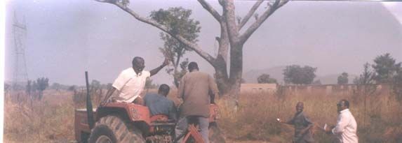
2

plough striking a rock - some provision must be made for protecting the implement, tractor and
hitch from excessive stresses. Excessive stress development on machine parts can be destructive
and every effort must be taken to prevent or eliminate this occurrence. Draught as an important
parameter that contributes to the development of stress has been investigated by various
researchers (Oni et al., 1992; Shirin et al., 1993; Fielke, 1996; Kushwaha and Linke, 1996;
McKyes and Maswaure, 1997; Onwualu and Watts, 1998; Al-Suhaibani and Al-Janobi, 1997;
Manian et al., 2000; Shrestha et al., 2001; Gratton et al., 2003; McLaughlin and Campbell, 2004;
Mamman and Oni, 2005; Manuwa and Ademosun, 2007). Natsis et al. (2002) used tillage force
dynamometer to measure draught of mouldboard plough in a clay soil.

The specific draught of agricultural tools and implements varies widely under different
conditions. Strain gauges also known as electrical dynamometers are frequently used in
mechanical engineering research and development to measure the stresses generated by
machinery.

                                                   Direction of Motion

                   Bracket

                                                                                            Rear Axle

                                                                                             Bracket

                                                                                            Stabilizer

                                                                                            ‘U’ Bolt
              Direction of Swing
                   Draw bar

                                   Figure1. Steyr Tractor Lift System
     In the Steyr tractor lift system, the stabilizer (Figure 1) is the rigid type. The Steyr stabilizer
at one end has an oval shaped ring connected through a ‘U’ bracket bolted to the lower link and
at the other end is a ball ring connecting it to the triangular bracket bolted to the rear axle. The
‘U’ bolt connecting the stabilizer shaft to the lower link has a problem of much freedom for

______________________________________________________________________________
S. Sule, M. G. Yisa and C. N. Ohanwe. ‘Effect of Ploughing Speed on Stress Development on the
 Steyr Tractor Lift System on Clay Loam Soil Of Bauchi-Nigeria in the Northern Guinea
 Savannah’. Agricultural Engineering International: the CIGR Ejournal. Manuscript PM 07 029.
 Vol. IX. November, 2007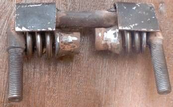
3

sideways swings of the stabilizer shaft. These sideways swings contribute to tractor instability
both during transportation and operation. Mijinyawa and Adetunji (2005) stated that 61.8% of
the farmers in Oyo and Osun states of Nigeria have access to only untarred roads and that farm
roads were found to be very deplorable. This is not a problem limited to only that part of Nigeria
alone but also to other parts; this part inclusive. Impact stress (shocks) resulting from the
sideway swings have led to failures of some parts of the lift system such as the stabilizer bracket.
This failure is in the form of breakages of either the pin or the bracket at the right hand side of
the lift system which sometimes leads to the damage of the axle and may lead to the replacement
of the entire axle. Preliminary investigations conducted in some establishments in Bauchi,
Gombe and Plateau States of Nigeria showed that this is a prominent problem in the listed region
not only existing in Steyr products but also in some other tractor makes.

The objective of this work is to verify the effect of speed of ploughing on the development of
stress on the brackets and stabilizers of the three-point linkage system of the Steyr tractor on a
clay loam soil of Bauchi in the Northern Guinea Savannah of Nigeria as a possible cause of the
failures of the lift system. This was necessary after it was confirmed through researches (sule,
2007) that the failure was neither as a result of abuse nor the use of poor materials. It is also
aimed at reducing the stress and recommends an optimum ploughing speed.

                               2. MATERIALS AND METHODS

The following materials were used in this experiment: A fifty by thirty meters portion of land
(measured out of the irrigation plot of the Agricultural Engineering Department of the Federal
Polytechnic, Bauchi, Nigeria), four digital multimeters, strain gauges, 9V batteries, resistors,
cables, Steyr 768 tractor and a metering tape, sand paper, detergent, water and glue.

The surfaces of the stabilizer shafts and brackets were properly cleaned using sand paper,
detergent and water. They were left to dry after which the strain gauges were carefully attached
using glue. Quarter-bridge strain gauge circuit with temperature compensation was used. They
were pressed firmly and allowed to dry after which they were soldered and wired with resistors
of equal resistance value. Figure 2 shows the circuit diagram of the electrical wiring. Soil
samples were taken from the experimental plot for analysis. The soil type was determined using
the method of soil type analysis (Michael, 1999). Other properties such as soil moisture content
(dry basis, db) and bulk density were determined. The implement was coupled and the ploughing
was started. Two assistants ran behind the tractor on both sides taking readings from the
multimeters mounted on the tractor mudguards. The speeds of ploughing were changed using the
hand throttle. The ploughing depth was fixed using the depth controller. The ploughed depth was
measured using a steel measuring tape with the undisturbed soil surface as a point of reference.

______________________________________________________________________________
S. Sule, M. G. Yisa and C. N. Ohanwe. ‘Effect of Ploughing Speed on Stress Development on the
 Steyr Tractor Lift System on Clay Loam Soil Of Bauchi-Nigeria in the Northern Guinea
 Savannah’. Agricultural Engineering International: the CIGR Ejournal. Manuscript PM 07 029.
 Vol. IX. November, 2007
4
SG R
V
Vi
SG R
Figure 2. Circuit Diagram for Double Strain Gauge Connection
Where, R is the external resistor; Vo is voltage output while Vi is the input voltage and SG is the
strain gauge.
The measurements were first taken with the original Steyr ‘U” bolt in place (Fig.1). Averages of
ten measurements were used. The obtained stress values were relatively higher than the yield
point of the bracket material. These stress values were used in the design and construction of
spring for the spring loaded (Modified) ‘U’ bolt (Plate 1). This was fitted in place for
comparative measurements. The design and construction of the spring loaded ‘U’ bolt is not
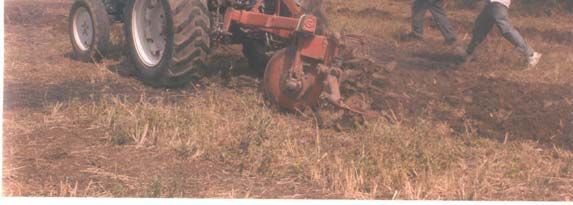
within the scope of this presentation. Plate II shows the measurements in progress.
Figure 1. Modified ‘U’ Bolt
______________________________________________________________________________
S. Sule, M. G. Yisa and C. N. Ohanwe. ‘Effect of Ploughing Speed on Stress Development on the
Steyr Tractor Lift System on Clay Loam Soil Of Bauchi-Nigeria in the Northern Guinea
Savannah’. Agricultural Engineering International: the CIGR Ejournal. Manuscript PM 07 029.
Vol. IX. November, 20075
Figure 2. Measurements in progress
3. RESULTS AND DISCUSSION
During the ploughing, the stresses on the brackets and on the stabilizer shafts were converted to
voltages and read on the digital multimeters as the output voltages. Using the following
relationships, these voltages were converted to stress (N/m2). Table1 shows the averages of ten
readings.
dR
strain sensitivity, f =
Rε
dL
Mechanical Strain ε =
L
dR 1
∴ ε= ×
R f
From Krutz et al (1984), when two gauges are used, one as a dummy,
dR
Vo = × Vi
2R
Where
Vo = Voltage out
Vi = Voltage in
E ⎛ 2Vo ⎞ 1
σ= ⎜ ⎟×
1 − ν 2 ⎝ Vi ⎠ f
where:
______________________________________________________________________________
S. Sule, M. G. Yisa and C. N. Ohanwe. ‘Effect of Ploughing Speed on Stress Development on the
Steyr Tractor Lift System on Clay Loam Soil Of Bauchi-Nigeria in the Northern Guinea
Savannah’. Agricultural Engineering International: the CIGR Ejournal. Manuscript PM 07 029.
Vol. IX. November, 20076
σ = stress
E = Young’s modulus of elasticity
ν = Poisson’s ratio
In case of ductile materials e.g. mild steel where the yield point is clearly defined, the factor of
safety is based upon the yield point stress (Chwiej, 1979).
Yield point stress
Factor of safety =
working stress
yield po int stress( yps)
ws =
Factor of safety ( fos )
Table 1 Effect of Speed on Stress on Right and Left Stabilizer on Clay Loam Soil
Speed (km/hr) Stress on Right Bracket (N/mm2) Stress on Left Bracket
(N/mm2)
Steyr U Bolt Mod. U Bolt Steyr U Bolt Mod. U Bolt
6.5 39.0 3.5 14 1.6
7.0 43.5 4.4 16 1.8
8.3 55.6 7.0 25 4.5
9 71.0 15 38 8.7
Factor of safety for steel can be taken as 16 (Khurmi and Gupta, 2004). Yield point stress of the
bracket material is 230N/mm2 (sule, 2007). The maximum stress measured during the
experiment with the Steyr ‘U’ bolt (at the speed of 7km/hr) is taken as the working stress. This is
the average recommended ploughing speed(Kuczewski and Majewski, 1983).
yield po int stress ( yps) 230
ws = = N / mm 2 = 14 N / mm 2
Factor of safety ( fos ) 16
Since working stress 43.5N/mm is greater than 14N/mm2, it shows that there are chances of
2
occasional increases of stress as a result of stumps and non- uniformity of farmlands. The
presence of stumps and none uniformity of farmlands are some of the causes of shock stress on
the Steyr lift system which is very destructive to the system. It is therefore very important to
______________________________________________________________________________
S. Sule, M. G. Yisa and C. N. Ohanwe. ‘Effect of Ploughing Speed on Stress Development on the
Steyr Tractor Lift System on Clay Loam Soil Of Bauchi-Nigeria in the Northern Guinea
Savannah’. Agricultural Engineering International: the CIGR Ejournal. Manuscript PM 07 029.
Vol. IX. November, 20077 reduce the stress. This maximum stress developed was used in the design and construction of the spring for the modified ‘U’ bolt. Measurements were taken on the effect of speed on stress development on both the brackets and the stabilizers at 12.6% soil MC (db) while ploughing was done at the depth of 20cm and the width of 1m. The graphs on figures 3 to 6 show the effect of speed on stress development on brackets and stabilizers. From these graphs it can be seen that the stresses generally increase with the speed of ploughing. The graphs also show the regression establishing mathematical relationship between the stress on brackets and stabilizers and speed of ploughing when using the Steyr ‘U’ bolt and when using the modified type. Within the experimented limit the modified ‘U’ bolt is seen to be efficient. The discrepancies seen are as a result of variation of soil resistances on the field. It was however observed that the right side of the three point linkage system experienced much higher stresses than those on the left side of the system. This explains why failures of the bracket and the axle occur only on the right side. This is due to the greater side thrust tending to pull the plough from the right towards the left than from the left to the right. This in turn is due to the asymmetrical shape of the plough. This increase of stress with speed agrees with Kamal et al, (1999). On this soil, increase of ploughing speed above 7.0km/hr is seen to produce a very sharp increase in stress on both brackets and stabilizers. This stress is excessive and destructive to the stabilizer bracket when using the Steyr ‘U’ bolt (Sule et al, 2004). The use of the modified type is seen to reduce the stress from 43.5N/mm2 to 4.4N/mm2 on the soil of 12.6% moisture content (db) at 7km/hr. This stress reduction is achieved through shock absorption by the incorporated springs. Further studies (Figures 7 and 8) show that the stresses are generally higher on clay loam soils than on sandy loam soils and also that stresses decrease with a decrease in moisture content on the clay loam soil till at 12.6%. This reflects the observations of Ademosun (1990) and Gupta and Surendranath (1989). This reduction in stress with the reduction in moisture content can be attributed to the formation of a friable condition of the soil at lower soil moisture content. At the moisture content of 10.4% however, the stress begins to increase due to hardening of the soil. It is observed that for clay loam soil, the optimum soil moisture content that would guarantee a long lasting stabilizer – bracket system is 12.6%. It is worth noting however that the methodology employed here has some limitations in the sense that four assistants were engaged to run after the tractor to take the readings. This and the nature of the terrain of work limited the range of speed of work. This is also a proof that higher stresses could be experienced by the brackets and stabilizers in rougher terrains during the actual operations. For this reason, it is recommended that an X-Y plotter is used in future experiments of this nature where all the outputs from the multimeters will be fed into the X-Y plotters. ______________________________________________________________________________ S. Sule, M. G. Yisa and C. N. Ohanwe. ‘Effect of Ploughing Speed on Stress Development on the Steyr Tractor Lift System on Clay Loam Soil Of Bauchi-Nigeria in the Northern Guinea Savannah’. Agricultural Engineering International: the CIGR Ejournal. Manuscript PM 07 029. Vol. IX. November, 2007
8

                                         25

       Stress on Right Bracket [N/mm2]
                                                                                            y = 1.754x 2 - 21.858x + 76.991
                                                                                                     R2 = 0.9464                                 Steyr 'U' Bolt
                                         20

                                                                                                                                                 Modified 'U' Bolt
                                         15

                                                                                                                                                 Poly. (Steyr 'U'
                                         10                                                                                                      Bolt)
                                                                                   y = 1.4034x 2 - 18.808x + 66.543                              Poly. (Modified
                                         5                                                                                                       'U' Bolt)
                                                                                             R2 = 0.9988

                                         0
                                              0                                             2         4          6         8           10
                                                                                                  Speed [km/hr]

                                          Figure 3. Effect of Ploughing Speed on Stress Development on the Right
                                            Bracket (Clay Loam Soil of 12.6%M.C at 20cm depth of ploughing)

                                                                                   20
                                                  Stress on Left Bracket [N/mm2]

                                                                                   18                 y = 3.19x 2 - 45.425x + 168.06
                                                                                                               R2 = 0.9731                       Steyr 'U' Bolt
                                                                                   16
                                                                                   14
                                                                                                                                                 Modified 'U' Bolt
                                                                                   12
                                                                                   10
                                                                                                                                                 Poly. (Steyr 'U'
                                                                                   8                                                             Bolt)
                                                                                   6                                                             Poly. (Modified 'U'
                                                                                   4        y = 0.2016x 2 - 2.3706x + 10.001                     Bolt)
                                                                                   2                  R2 = 0.9998
                                                                                   0
                                                                                        0         2          4        6         8           10
                                                                                                          Speed [km/hr]

Figure 4. Effect of Ploughing Speed on Stress Development on the Left Bracket (Clay Loam Soil
   of 12.6%M.C at 20cm depth of ploughing)

______________________________________________________________________________
S. Sule, M. G. Yisa and C. N. Ohanwe. ‘Effect of Ploughing Speed on Stress Development on the
Steyr Tractor Lift System on Clay Loam Soil Of Bauchi-Nigeria in the Northern Guinea
Savannah’. Agricultural Engineering International: the CIGR Ejournal. Manuscript PM 07 029.
Vol. IX. November, 2007
9
20
Stress on Left Bracket [N/mm2]
18 y = 3.19x 2 - 45.425x + 168.06
R2 = 0.9731 Steyr 'U' Bolt
16
14
Modified 'U' Bolt
12
10
Poly. (Steyr 'U'
8 Bolt)
6 Poly. (Modified 'U'
4 y = 0.2016x 2 - 2.3706x + 10.001 Bolt)
2 R2 = 0.9998
0
0 2 4 6 8 10
Speed [km/hr]
Figure 5. Effect of Ploughing Speed on Stress Development on the Right Stabilizer (Clay Loam
Soil of 12.6%M.C at 20cm depth of ploughing)
40 y = 4.2424x 2 - 56.552x + 202.95
R2 = 0.9937
Stress on Left Stab. Bracket
35
Steyr 'U' Bolt
30
25 Modified 'U' Bolt
[N/mm2]
20
Poly. (Steyr 'U'
15 Bolt)
10 Poly. (Modified 'U'
2
y = 1.5737x - 21.649x + 75.976 Bolt)
5
R2 = 0.9958
0
0 2 4 6 8 10
Speed [km/hr]
Figure 6. Effect of Ploughing Speed on Stress Development on the Left Stabilizer (Clay Loam
Soil of 12.6%M.C at 20cm depth of ploughing)
______________________________________________________________________________
S. Sule, M. G. Yisa and C. N. Ohanwe. ‘Effect of Ploughing Speed on Stress Development on the
Steyr Tractor Lift System on Clay Loam Soil Of Bauchi-Nigeria in the Northern Guinea
Savannah’. Agricultural Engineering International: the CIGR Ejournal. Manuscript PM 07 029.
Vol. IX. November, 200710
60 y = 1.7545x 2 - 42.955x + 306.17
Stress on Right Bracket [N/mm2]
R2 = 0.9999
50
Steyr 'U' Bolt
40
Modified 'U' Bolt
30
Poly. (Steyr 'U' Bolt)
20 y = 0.6682x 2 - 16.357x + 104.89
R2 = 0.8099 Poly. (Modified 'U'
10
Bolt)
0
0 2 4 6 8 10 12 14 16
Moisture Content [%]
Figure 7 Stress Reduction Action of the Modified ‘U’ Bolt on the Right Bracket on Clay Loam
Soil at Different Moisture Content
y = 1.5692x 2 - 36.015x + 240.53
70
Stress on Right Bracket [N/mm2]
R2 = 0.9346
60
50 Steyr 'U' Bolt
40 Modified 'U' Bolt
30
Poly. (Steyr 'U' Bolt)
y = 0.4855x 2 - 11.163x + 65.645
20
R2 = 0.8581
Poly. (Modified 'U'
10
Bolt)
0
0 2 4 6 8 10 12 14
Moisture Content [%]
Figure 8 Stress Reduction Action of the Modified ‘U’ Bolt on the Right Bracket on Sandy Loam
Soil at Different Moisture Content
4. CONCLUSION AND RECOMMENDATION
______________________________________________________________________________
S. Sule, M. G. Yisa and C. N. Ohanwe. ‘Effect of Ploughing Speed on Stress Development on the
Steyr Tractor Lift System on Clay Loam Soil Of Bauchi-Nigeria in the Northern Guinea
Savannah’. Agricultural Engineering International: the CIGR Ejournal. Manuscript PM 07 029.
Vol. IX. November, 200711
The failure of the Steyr tractor lift system could be due to the development of occasional
excessive stress as a result of stumps and non uniformity of farmlands. The use of Steyr tractor to
plough on clay loam soil at speed higher than7km/hr encourages the development of destructive
stress on the lift system leading to the failures of the system. In order to avoid the
failures/breakdowns of the Steyr tractor lift system (stabilizer brackets and the axle), it is
recommended that the modified ‘U’ bolt is adopted for use on the Steyr tractor and ploughing
speed on this land is kept at or below 7.0km/hr. It is also recommended that for clay loam soil,
the optimum soil moisture content that would guarantee a moderate stress on the lift system is
12.6%.
The decision to use the spring loaded ‘U’ bolt rather than redesign the lift system is purely based
on economic reasons.
5. REFERENCES
Ademosun, O. C. 1990. The design and operation of a soil tillage dynamics equipment.
TheNigerian Engineer, 25 (1): 51-57.
Al-Suhaibani, S. A. and Al-Janobi, A. 1997. Draught requirements of tillage implements
operating on sandy loam soil. Journal of Agricultural Engineering Research, 66: 177–
182.
Barger, E. L., Liljedahl,J. B., Carleton,W. M and Mckibben, E. G. 1963. Tractors and their
power units. 2nd Edition. John Wiley and Sons Inc., New York.
Chwiej, M. 1979. Maszynoznastwo Ogolne(In Polish). Panstwowe Wydawnictwo Naukowe.
Warszawa.
Fielke, J.M. 1996. Interaction of the cutting edge of tillage implements with soil. Journal of
Agricultural Engineering Research, 63(1): 61-72.
Gratton, J., Chen, Y. and Tessier, S. 2003. Desgn of a spring –loaded downforce system for a
no- till seed opener. Canadian Biosystem Engineering, 45: 2.29—2.39.
Gupta, C. P and Surendranath 1989. Stress field in soil owing to tillage tool Interaction. Soil
and Tillage Research, 13: 123 – 149
Kamal, A. R., Odesanmi, 0. 0. and Onwualu, A. P. 1999. Effect of speed and depth of cut on
draught and power requirement of a disc plough. Research and information bulletin of
NCAM Vol.1.
Kushwaha, R.L. and Linke, C. 1996. Draught- speed relationship of simple tillage tools at
high operating speeds. Soil and Tillage Research, 39: 61 – 73
Kuczewski, J., Majewski, Z. 1983. Eksploatacja maszyn rolniczych (In Polish). Tom 1. PWRiL
Warszawa Pp. 19-27
Khurmi R. S. and J. K .Gupta. 2002. A text book of machine design. Eurasia publishing house.
New Delhi.
______________________________________________________________________________
S. Sule, M. G. Yisa and C. N. Ohanwe. ‘Effect of Ploughing Speed on Stress Development on the
Steyr Tractor Lift System on Clay Loam Soil Of Bauchi-Nigeria in the Northern Guinea
Savannah’. Agricultural Engineering International: the CIGR Ejournal. Manuscript PM 07 029.
Vol. IX. November, 200712
Krutz, G., Lester, T and Paul, C. 1984. Design of agricultural machinery. John Wiley and Sons,
New York. Pp77-111.
McKyes, E. and Maswaure, J. 1997. Effect of design parameters of flat tillage tools on
loosening of a clay soil. Soil and Tillage Research, 43: 195-204.
McLaughlin, N.B. and Campbell, A. J. 2004. Draft-speed-depth relationships for four liquid
manure injectors in a fine sandy loam soil. Canadian Biosystem Engineering, 46: 2.1-
2.5.
Manian, R., Rao, V.R. and Kathirvel, K. 2000. Influence of operating and disk parameters on
performance of disk tools. Agricultural Mechanization in Asia, Africa And Latin
America, 31(2): 19-26, 38.
Michael, A. M. 1999. Irrigation — Theory and practice. Vikas Publishing House PVT Ltd, New
Delhi
Mijinyawa, Y and J.Adetunji. 2005.Evaluation of farm transportation system in Osun and Oyo
States of Nigeria. Agricultural Engineering International: the CIGR Ejournal. Vol.
VII. Manuscript LW 05 004. September, 2005.
Manuwa, S and O. C. Ademosun. 2007. Draught and soil disturbance of model tillage tines under
varying soil parameters. Agricultural Engineering International: the CIGR Ejournal.
Manuscript PM 06 016. Vol. IX. March, 2007.
Mamman, E. and K. C. Oni. 2005. Draught performance of a range of model chisel
furrowers. Agricultural Engineering International: the CIGR Ejournal. .PM 05 003.
Vol. VII. November 2005.
Onwualu, A.P. And Watts, K.C. 1998. Draught and vertical forces obtained from dynamic
soil cutting by plane tillage tools. Soil and Tillage Research, 48: 239-253.
Oni, K.C.,Clark, S.J.and Johnson, H.W. 1992. The effects of design on the draught of undercut
sweep tillage tools. Soil and Tillage Research, 22:117-130.
Otmianowski, T. 1983. Procesy odnowy maszyn rolniczych. PWRiL. Warszawa.
Sule, S, M.G. Yisa and Y.D Ali. 2004. Empirical determination of stress on the Steyr tractor
stabilizer bracket system. Nigerian Journal of Industrial and Systems Studies. Vol.3,
No.2. pp 54-57
Sule, S. 2007. Improvement of the performance of the U-bolt incorporating springs as a stress
reducer for the Steyr-tractor Stabilizer. Unpublished Ph.D thesis. Mechanical
Engineering Programme, Abubakar Tafawa Balewa University, Bauchi, Nigeria.
Shrestha, D. S. Singh, G. and Gebresenbet, G. 2001. Optimizing design parameters on a
mouldboard plough. Journal of Agricultural Engineering Research, 78(4): 377 – 389.
Shirin, A.K.M., Hoki, M. and Salokhe, V.M. 1993. Effects of disc and working parameters
on the performance of a disc plough in a clay soil. Agricultural Mechanization in
Asia, Africa And Latin America, 24(4): 9-12.
______________________________________________________________________________
S. Sule, M. G. Yisa and C. N. Ohanwe. ‘Effect of Ploughing Speed on Stress Development on the
Steyr Tractor Lift System on Clay Loam Soil Of Bauchi-Nigeria in the Northern Guinea
Savannah’. Agricultural Engineering International: the CIGR Ejournal. Manuscript PM 07 029.
Vol. IX. November, 2007You can also read