Efficiency of the Nam Theun 2 hydraulic structures on water aeration and methane degassing
←
→
Page content transcription
If your browser does not render page correctly, please read the page content below

Hydroécol. Appl.
© EDF, 2015
DOI: 10.1051/hydro/2015002

Efficiency of the Nam Theun 2 hydraulic structures
on water aeration and methane degassing

Efficacité des structures hydrauliques de Nam Theun 2
sur l’aération de l’eau et le dégazage du méthane

S. Descloux(1)*, V. Chanudet(1), B. Taquet(1), W. Rode(2), P. Guédant(2),
D. Serça(3), C. Deshmukh(3), F. Guerin(4,5)

(1) EDF, Hydro Engineering Centre, Sustainable Development Department, Savoie-Technolac, 73373 Le
    Bourget-du-Lac, France
    stephane.descloux@edf.fr
(2) Nam Theun 2 Power Company Limited (NTPC), Environment & Social Division – Water Quality and
    Biodiversity Dept.– Gnommalath Office, PO Box 5862, Vientiane, Lao PDR
(3) Laboratoire d’Aérologie, Observatoire Midi-Pyrénées, 14 Av. Édouard Belin, 31400 Toulouse, France
(4) Université de Toulouse, UPS (OMP), LMTG, 14 Av. Édouard Belin, 31400 Toulouse, France
(5) IRD, LMTG, 14 Av. Édouard Belin, 31400 Toulouse, France

Abstract – Release of hypolimnetic water from man-made reservoirs can be a problem for
downstream rivers. These effects can be significant mainly during the first years after the
reservoir impoundment, especially in thermally stratified reservoirs favouring the release of
anoxic methane-rich water. In tropical areas, higher temperatures decrease the oxygen solu-
bility and enhance chemical processes responsible for the rise of reduced compounds. The
Nam Theun 2 Reservoir was first filled in 2008. It experienced hypolimnetic deoxygenation
and significant methane concentrations during the first 2 years. Dedicated structures to oxy-
genate water and degas methane were designed during the study phase. The overall aerating
and degassing effects of these hydraulics structures varied from very good to moderate.
Results depend on the continuous water quality improvement with time as well as on the limi-
ted range of upstream oxygen and methane concentrations tested. The hollow jet valve and
the concrete tooth shaped structure were very efficient together with downstream natural tur-
bulence in aerating/degassing compared to the staggered baffle blocks. Contrary to other
structures, the efficiency of the baffle blocks structure is reduced with high discharges. The
aeration weir showed a moderate efficiency in supplying oxygen to the water due to the high
upstream oxygen saturations (close to 100%). However, it was very efficient for methane
degassing even at low concentrations. Hydraulics structures of the Nam Theun 2 project are
an efficient, reliable and low maintenance way to improve oxygen content and to degas
methane.

Key words – aeration, reservoir, sub-tropical, weir, degassing, oxygen, methane

                                Article publié par EDP Sciences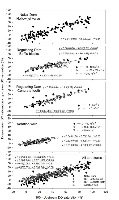
2                                       S. Descloux et al.

Résumé – La délivrance d’eau provenant de l’hypolimnion des réservoirs artificiels peut être
un problème pour la qualité de l’eau des rivières en aval. Ces effets peuvent être importants
pendant les premières années après la mise en eau d’un réservoir et plus particulièrement
dans les réservoirs stratifiés favorisant la délivrance d’une eau anoxique et riche en méthane.
Dans les régions tropicales, les températures plus élevées diminuent la solubilité de l'oxy-
gène et favorisent les processus chimiques responsables de l’augmentation des concentra-
tions en composés réduits. Le réservoir de Nam Theun 2 a été mis en eau en 2008. Il a
présenté une désoxygénation de la couche hypolimnique et des concentrations significatives
de méthane au cours des 2 premières années. Des structures dédiées à l’aération et au déga-
zage du méthane ont été étudiées et mises en œuvre sur le site. L'efficacité globale de l’aéra-
tion et du dégazage des différentes structures hydrauliques a été de très bonne à modérée.
Les résultats sont évalués en tenant compte de l’amélioration continue de la qualité de l’eau
et de la faible gamme de variation de concentrations d’oxygène dissous et de méthane dis-
sous amont. La vanne à jet creux et la structure en forme de dent en béton ont été très effi-
caces avec la turbulence naturelle aval pour l’aération et le dégazage comparativement aux
blocs de dissipation. Contrairement à d'autres structures, l'efficacité de la structure en blocs
de dissipation est réduite à fort débit. Le seuil aérateur a été modérément efficace pour
l'apport d’oxygène compte tenu des hautes saturations amont (près de 100 %) mais il a été
très efficace pour le dégazage du méthane, même à de faibles concentrations. Les structures
hydrauliques du projet Nam Theun 2 s’avèrent efficaces pour aérer et dégazer le méthane.
Elles sont fiables et nécessitent une faible maintenance.

Mots clés – aération, réservoir, sub-tropical, seuil, dégazage, oxygène, méthane

1 INTRODUCTION                                     concentration of reduced and dis-
                                                   solved compounds. Among them, it
    Release of hypolimnetic water from             can be found ammonium (NH4+), fer-
man-made reservoirs can alter the                  rous iron (Fe2+), hydrogen sulfide
physical and chemical quality of down-             (H2S), carbon dioxide (CO2) and meth-
stream rivers, limit their uses and lead           ane (CH4) (Galy-Lacaux et al., 1997,
to a loss of biodiversity. These effects           1999; Guérin et al., 2008). Concentra-
can be significant during the first years          tions are generally higher when the
after impoundment or under strong res-             water body is stratified (Abril et al.,
ervoir stratification events and, are              2005). Under such conditions, hypolim-
generally enhanced in tropical areas               netic waters are isolated from the sur-
where higher temperatures decrease                 face waters oxygenated from photo-
the oxygen solubility and enhance the              synthesis and atmospheric gas
chemical processes of organic matter               exchange by the presence of a thermo-
degradation (Townsend, 1999; Abril                 cline. Waters in hydroelectric reser-
et al., 2005; Gregoire & Descloux,                 voirs are generally taken from the bot-
2009).                                             tom layer, i.e. in the hypolimnion, to
    Newly impounded reservoirs cause               maximise energy production (optimi-
the degradation of the flooded organic             sation of the live volume). The release
matter that can lead to anoxia and high            of bottom waters can thus affect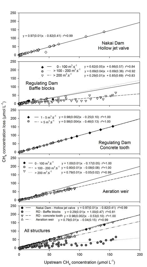
Efficiency of the Nam Theun 2 hydraulic structures on water aeration        3

downstream rivers throughout the year                 concentrations. Opposite results have
or during specific seasons, for example               been underlined with acute toxic gas
during the dry season when the river                  effects in marine fish starting at a con-
can be mostly influenced only by reser-               centration of about 1 mg.L-1 (Patin,
voir releases. As rivers are generally                1999). But methane has the indirect
used for various purposes (drinking                   detrimental effect of reducing DO con-
water, biodiversity, navigation and                   tent in oxic water bodies.
tourism, etc) and fulfill the function of                 To maintain DO and gas concentra-
self-purification, it is of high importance           tions compatible with aquatic life and
to preserve and guaranty their water                  other uses, many solutions have been
quality.                                              tested to supply DO (namely aeration;
    The minimum levels of (i) dissolved               Baylar et al., 2009). Solutions range
oxygen (DO) to be maintained and (ii)                 from hypolimnetic oxygen injection,
reduced gas to be eliminated vary from                reservoir clearing and selective with-
site to site and with the physico-chemi-              drawal to the construction of dedicated
cal characteristics of the water, the                 hydraulic structures like weirs or baffle
morphology of the river and the dilution              blocks. Creation of turbulence by
effect from downstream tributaries. It                hydraulic structures and subsequent
also depends on the ecological require-               aeration is a principle utilized by aera-
ments of the aquatic community and on                 tion weirs and seems to be the most
the latitude (e.g. oxygen solubility is               efficient solution for aeration (Chanson,
a function of water temperature). The                 1995; EPRI, 2002; Emiroglu & Baylar,
downstream DO consumption by ben-                     2003). DO transfer occurs when air is
thic community respiration or biological              entrained into the flow in the form of a
and chemical DO demand must also be                   large number of bubbles. These bub-
considered. For instance, salmonids                   bles greatly increase the surface area
swimming is altered below 2–5 mg.L-1                  available for mass transfer (Baylar
DO whereas tilapia and carps can swim                 et al., 2009). Very few man-made res-
at DO levels of 1–2 mg.L-1 (Kutty, 1972;              ervoirs are equipped for aeration with
Kutty & Saunders, 1973). Tropical                     respect to the total number of reser-
fishes generally have a higher toler-                 voirs throughout the world. Structures
ance of low DO. Nevertheless, DO that                 built with the objective of degassing
remains below 1 mg.L-1 (and corre-                    reduced gases are even more rare and
sponding DO saturations equivalent to                 the current literature data are based on
~ 10% at 20 °C) for a few hours can                   the only case of the Petit Saut Reservoir
affect biodiversity and generally result              in French Guiana (Gosse & Gregoire,
in large fish kills (Baylar et al., 2009).            1997; Gosse et al., 1997). Moreover,
Studies of the direct effects of methane              efficiency of other structures like hollow
on water organisms are very limited.                  jet valves that are not specifically
Sackett and Brooks (1975) have shown                  designed to increase DO concentration
that under experimental conditions,                   or to degas have never been assessed
hydrocarbons (methane and others)                     on site.
did not cause harmful effects on marine                   The creation of the Nam Theun 2
phytoplankton even at high dissolved                  Reservoir (NT2) in the Lao PDR has led
4                                       S. Descloux et al.

to the submersion of 489 km² of forest             Intake in the upper part of the reservoir,
and agricultural soils. Descloux et al.            channelled through the Pressure Tunnel,
(2011) have estimated the quantity of              the Power House, then released into the
flooded carbon including above ground              Regulating Pond equipped with a Reg-
and below ground biomass to 5.1 MtC.               ulating Dam (used to buffer discharge
It was foreseen that the major part of the         variations of the Power House) and into
DO consumption would come from the                 the 27 km long Downstream Channel
decomposition of this organic matter               (through the Aeration Weir) which joins
(mainly from the soils). In addition, other        the Xe Bangfai River about 30 km south
processes can increase DO consump-                 of the Power House (Descloux et al.,
tion, such as respiration from aquatic             same issue). The Regulating Dam which
plants and chemical oxidation (iron and            also receives water from the upstream
other metals such as Mn in soils). The             Nam Kathang River also delivers a min-
residence time of the NT2 Reservoir is             imum flow towards the downstream
about 6 months, which is relatively long,          Nam Kathang River, a tributary of the
and the water body is stratified about             Xe Bangfai River. The Nakai Dam is
half a year during the warm season                 located in the lower part of the reservoir
(Chanudet et al., same issue). These               far (around 40 km) from the water intake
characteristics may affect DO concen-              and delivers a riparian release to the
trations and generate reduced gases                Nam Theun River for environmental con-
and it was decided during the study                siderations. The mean annual inflow in
phase to build dedicated structures to             the Nam Theun Reservoir is 238 m3.s-1
increase DO concentrations and to degas            (Descloux et al., same issue). The NT2
supersaturated gases. Moreover, for                Reservoir is relatively shallow with an
the NT2 Project, the guideline for mini-           average depth of 8 m and is character-
mal DO is fixed at 5 mg.L-1, a target for          ized by a large drawdown area. The res-
all the re-aeration structures.                    ervoir surface fluctuates from 86 km² at
     The objectives of this study were i)          the minimum operating level (525.5 masl)
to determine the aeration and methane              to 489 km² at the full supply level (538
degassing efficiency of dedicated and              masl; DTG, 2012; Descloux et al., same
non-dedicated structures of the NT2                issue). Three seasons are distinct in this
project over 5 years following the first fill-     sub-tropical environment; the warm-wet
ing of the reservoir and ii) to compare the        (WW: July to October), cool-dry (CD:
efficiency of these hydraulic structures.          November to February) and warm-dry
                                                   (WD: March to June) seasons (Descloux
2 METHODS                                          et al., same issue).

2.1 Study site                                     2.2 Aerating and degassing
   The NT2 Project, located in Lao                 structures of the NT2 Project
PDR, was impounded in April 2008 and
                                                   2.2.1 The Nakai Dam
commissioned in April 2010. The reser-
voir is located on the Nakai Plateau. The              The concession agreement stipu-
turbinated water is captured at the                lates that the Nam Theun 2 Power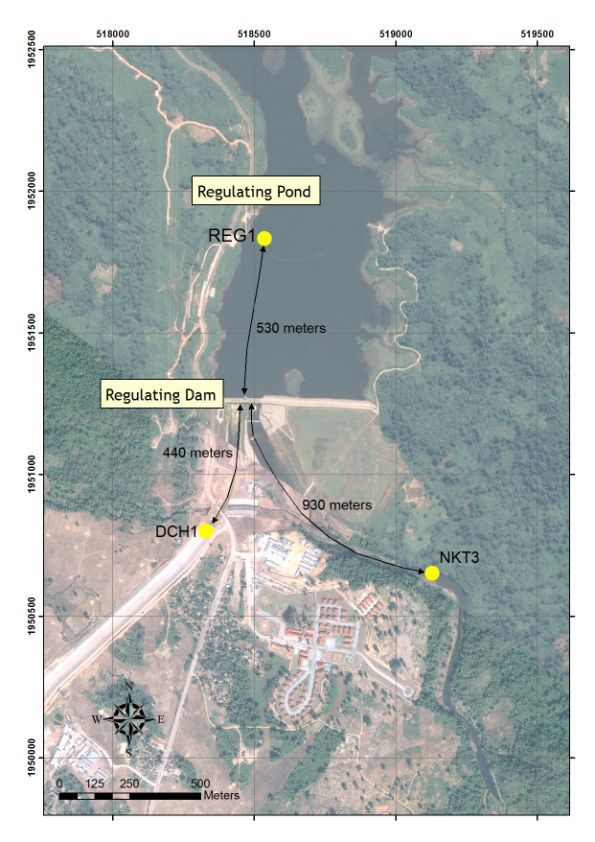
Efficiency of the Nam Theun 2 hydraulic structures on water aeration            5

Fig. 1. Picture of the riparian release structure of the Nakai dam site on the Nam Theun River (hollow
jet valve).
Fig. 1. Photographie du débit réservé relâché au site du barrage de Nakai sur la rivière Nam Theun
(vanne à jet creux).

Company (NTPC) has to release a                         the Downstream Channel water release
minimum environmental flow of 2 m3.s-1                  (passing through point DCH1 in Fig. 5B).
into the downstream Nam Theun River.                    Based on the water level difference
This flow is taken from the reservoir                   between the reservoir and the channel,
surface, 2 meters below the surface,                    around 40 MW of energy (which corre-
through a multi-level off-take structure                sponds to approximately 315 m3.s-1)
(diameter 1.54 m). The flow then goes                   have to be dissipated downstream of
through a hollow jet valve (section of                  the gates. A model was built to design
5 x 3.7 m) that creates turbulence oxy-                 adequate features with the objective of
genating the flow (Figs. 1 and 5A)                      dissipating this flow energy. A decision
which reaches a designed stilling basin                 was made to dissipate this energy with
before its release into the Nam Theun                   staggered baffle blocks installed in a
River. Air is also entrained into the                   convergent section (7 blocks 3 m high,
basin and it is the combined efficiency                 12 m width and 4 m long), made with
of the two devices (jet and basin) and                  high strength concrete (60 MPa), as
the natural aeration along the 0.7 km                   shown in Figure 2. The high turbulence
downstream river stretch that was                       created by the energy dissipation
assessed in this study. During high                     devices is deemed to produce a good
floods, flow can be spilled out through                 aeration of the water, for all the range
flap and radial gates.                                  of discharges.
                                                            The second outlet is through the
2.2.2 The Regulating Dam                                ‘restitution gate’ which releases flows
                                                        higher than 1 m3.s-1 dedicated to the
    The Regulating Dam has three out-                   Nam Kathang River (Descloux et al.,
lets. The first structure is dedicated to               same issue and point NKT3 in Fig. 5B).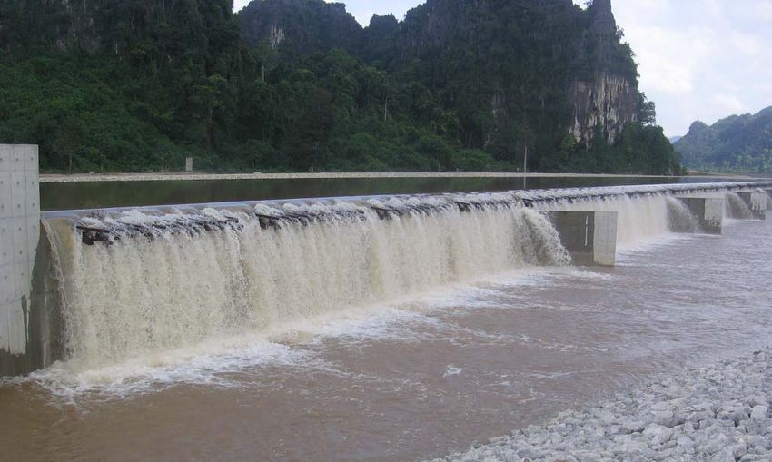
6                                          S. Descloux et al.

Fig. 2. Picture of the staggered baffle blocks installed downstream of the Regulating Dam in a conver-
gent section in the Downstream Channel.
Fig. 2. Photographie des blocs de dissipation installés en aval du barrage de démodulation dans le
chenal aval.

It is capable to release the natural                  Dam to aerate/degas the flow and thus
upstream inflow plus 10 or 15 m3.s-1,                 improve water quality in the Down-
depending on the power station opera-                 stream Channel before it flows into the
tion and natural inflows (from the upper              Xe Bangfai (Fig. 5C). It is a dedicated
Nam Kathang) into the Regulating                      structure designed to provide maximum
Pond. It has a capacity of 30 m3.s-1 at               aeration at the maximum flow of
the minimum operating level. In order to              330 m3.s-1. The structure includes a U-
provide a good aeration, a dedicated                  shaped weir made of reinforced con-
concrete tooth shaped device has been                 crete walls. The total overflow crest
designed to split the flow jet in 2 parts,            length is approximately 340 m. Sub-hor-
and spread it, in order to create a large             izontal perforated wooden devices are
area of water in contact with air (Fig. 3).           attached to the total overflow crest
The third outlet is a single canal that               length (allow to spread the flow over
delivers the minimum environmental                    1.2 m). They divide the flow over the
flow (below 1 m3.s-1) to the Nam Kathang              weir into multiple discharges to increase
during the dry season. The dedicated                  the water surface area as much as pos-
concrete tooth shaped device is not                   sible to provide maximum aeration/
used with this configuration.                         degassing potential. The weir height
                                                      from crest to the downstream water
2.2.3 The Aeration Weir                               level is greater than 1.5 m at normal flow
                                                      (330 m3.s-1), with a water mattress
   A weir was built approximately                     depth almost equal to 3 m (Fig. 4). The
8.3 km downstream from the Regulating                 structure performance was firstly tested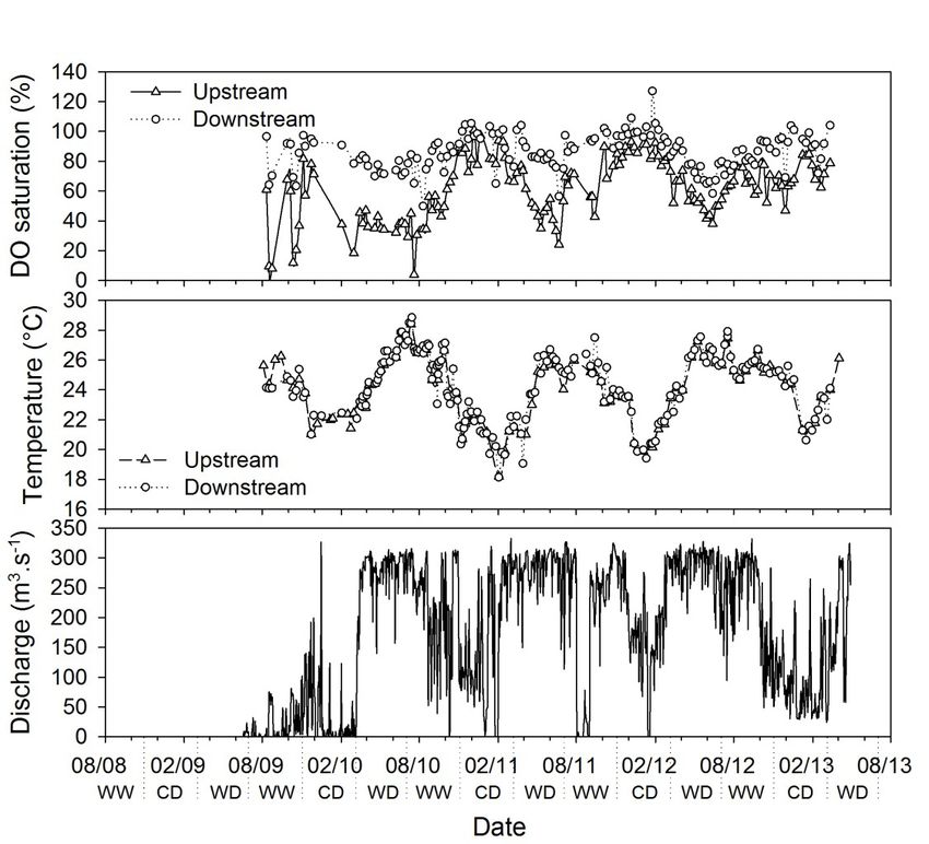
Efficiency of the Nam Theun 2 hydraulic structures on water aeration           7

Fig. 3. Picture of the concrete tooth shaped structure downstream of the Regulating Dam in the Nam
Kathang River.
Fig. 3. Photographie des dents en béton installées en aval du barrage de démodulation dans la
rivière Nam Kathang.

Fig. 4. Picture of the aerating weir downstream of the regulating dam in the Downstream Channel.
Fig. 4. Photographie du seuil aérateur installé en aval du barrage de démodulation dans le chenal
aval.

by a physical model study that focused                  speed in the Downstream Channel from
on bubble trajectories, and allowed the                 the Regulated Dam to the Aerating Weir
designers to implement deflection walls                 was calculated to approximately 1.7 m.s-1
(vertical concrete wall attached to the                 at 330 m3.s-1. The Downstream Channel
main structure; Fig. 4). The water flow                 is 56 m width (20 m horizontal and on
8                                     S. Descloux et al.

each side: 2 x 3 m with a 3/1 slope and          station (Descloux et al., same issue).
2 x 6 m with a 2/1 slope).                       The analytical methods, with the asso-
    Other small weirs are situated all           ciated limits of detection and uncertain-
along the Downstream Channel and are             ties (2% for DO saturation and 5% for
able to increase DO concentrations and           CH4) are summarized in Deshmukh
degas remaining reduced gases with               et al. (2014) and Chanudet et al. (same
lower efficiencies. Nevertheless, there          issue). In the reservoir, between three
is no small weir between the Regulating          and six samples were taken (peristaltic
Dam (DCH1) and the Aeration Weir                 pump or sampling bottle) at each sam-
(DCH2) and the Aeration Weir (DCH2)              pling point according to water column
and the sampling station downstream              and oxycline depths. In the rivers, only
the Aeration Weir (DCH3). The Tunnel             surface water was collected.
outlet structure at the end of the Down-             All the upstream/downstream meas-
stream Channel is also dedicated to              urements were done between 11 am
dissipate the energy of the flow while           and 2 pm within 2 hours (excepted for
creating high turbulences. These struc-          REG1/NKT3 where the measurements
tures are not included in the present            were done within 24 hours due to field
study as no water quality monitoring             constraints; this does not affect the
was conducted there.                             quality of the analysis as the transfer
                                                 time is greater than the lag time between
                                                 the two measurements). The upstream
2.3 Physico-chemical                             measurement has always been done
measurements                                     before the downstream measurement.
                                                 The oxygen values for 100% saturation
     The physico-chemical water quality          at 20 °C, 25 °C and 30 °C are respec-
characteristics have been monitored in           tively 9.07, 8.24 and 7.54 mg.L-1.
the NT2 system (hydroelectric reservoir
and downstream rivers) since the first
filling of the reservoir in April 2008. The      2.4 Data analysis
results emphasize that the impound-
ment of the reservoir induced a sub-             2.4.1 The Nakai Dam
stantial modification of the water quality
in the whole aquatic system which is                 For aeration and degassing analysis
partially controlled by the hydrodynam-          at the dam site, upstream concentra-
ics in the reservoir. During the WD and          tions were calculated from measure-
WW seasons, the reservoir water col-             ments at RES1 (situated in the reservoir
umn is thermally stratified with a warm          around 700 m upstream of the dam) and
oxic epilimnion and a cooler anoxic              downstream concentrations were meas-
hypolimnion (Chanudet et al., same               ured about 700 m from the release at the
issue).                                          NTH3 station (Fig. 5A; Descloux et al.,
     DO and methane (CH4) concentra-             same issue). At RES1, the thickness
tions in water were measured weekly,             and the depth of the water layer used for
fortnightly or monthly between April             calculation of the upstream concentration
2008 and April 2013 at each monitoring           depend on the discharge and restitution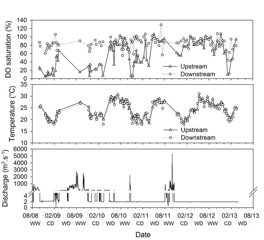
Efficiency of the Nam Theun 2 hydraulic structures on water aeration              9

                                                                            A

                                            B                                                C

Fig. 5. Localisation of the sampling stations and length between stations and structures at A) the
Nakai Dam, B) the Regulating Pond and C) the Aerating Weir (© NTPC).
Fig. 5. Localisation des stations d’échantillonnage et distances entre les structures et les stations au
A) barrage de Nakai, B) bassin de démodulation et C) seuil aérateur (© NTPC).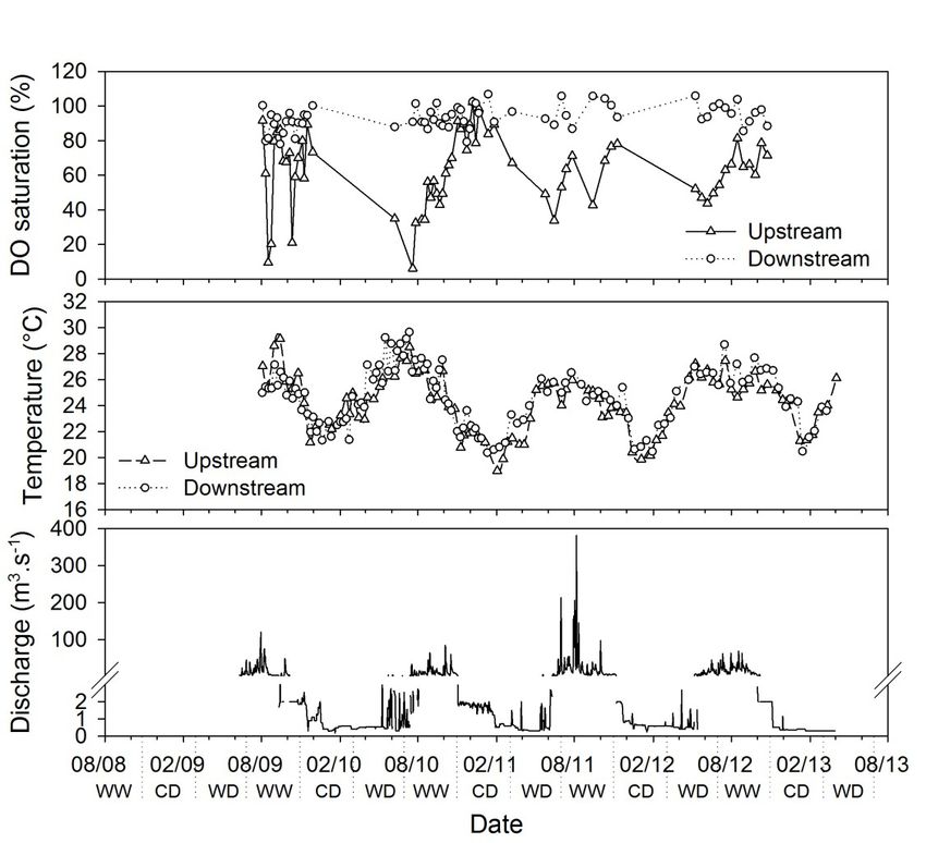
10                                   S. Descloux et al.

structure (riparian release, flap gates or      (29%, 17.0 m3.s-1 in average). The
radial gates). For low discharges (e.g.         remaining measurements (45%), done
the riparian release; Q ≈ 2 m3.s-1),            for discharge < 1 m3.s-1, were not con-
velocity measurements and simulations           sidered as water was not released
(Fabre et al., 2010) show that only the         through the restitution gate: the dedi-
uppermost 3 meters are withdrawn                cated concrete tooth shaped device is
through the multi-level off-take struc-         not used with this configuration. For the
ture used for the riparian release. Most        two discharge classes, the flow is with-
of the measurements (70% for DO and             drawn through a sector gate opening
93% for CH4) were carried out with such         from 9 to 11 m below the surface. For
a low discharge. The depth and thick-           the two classes, upstream concentra-
ness of the water layer to consider for         tions were calculated by integrating the
higher discharges entering the multi-           whole water column at REG1: meas-
level off-take structure are more deli-         urements show that the physico-chem-
cate to estimate. In this paper, only the       ical parameters (DO or temperature for
flow passing through the intake surface         instance) are almost constant over the
structure and the hollow jet valve used         water column (Chanudet et al., same
for the riparian release are considered.        issue). For instance, since the commis-
DO measurements at RES1 (vertical               sioning, the difference between surface
resolution: surface level (0.2 m), then         and depth-averaged DO saturation did
every 0.5 m in the uppermost 5 m and            not exceed 3% in average. This homo-
every 1 m downwards) were directly              geneity precluded any attempt to trace
integrated over the uppermost 3 meters          upstream water with physico-chemical
to get an average DO value while CH4            parameters such as conductivity for
measurements were linearly interpo-             instance to assess the exact water
lated to calculate the CH4 concentration        thickness to consider. Therefore, the
in the uppermost 3 meters (based on             choice of the water layer does not affect
CH4 measurements made at the sur-               significantly the results and it justifies
face and 1 m above the oxycline usually         the use of a unique upstream concen-
found between 5 and 10 m; Chanudet              tration calculation method whatever the
et al., same issue).                            discharge. Downstream concentrations
                                                were measured at the surface at the
2.4.2 The Regulating Dam and the                NKT3 station (Fig. 5B; Descloux et al.,
Aeration Weir                                   same issue).
                                                    Releases in the Downstream Chan-
    The aeration and degassing effi-            nel were also divided into three dis-
ciencies of the Regulating Dam (into the        charge classes: 0-100 m3.s-1 (24%,
Downstream Channel and in the Nam               38.9 m3.s-1 in average for DO analysis),
Kathang River; Fig. 5B) were analysed           >100-200 m3.s-1 (16%, 147.1 m3.s-1 in
considering several discharges classes.         average) and > 200 m3.s-1 (59%,
Releases in the Nam Kathang using the           280.3 m3.s-1 in average). For these
‘restitution gate’ were divided into two        three classes, upstream concentrations
discharges classes: 1-5 m3.s-1 (26%,            were calculated by integrating the whole
2.3 m3.s-1 in average) and > 5 m3.s-1           water column at REG1, considering the
Efficiency of the Nam Theun 2 hydraulic structures on water aeration 11
Cd – Cu
vertical homogeneity of the water, the E = --------------------
- (Eq. 2)
low water depth close to the gates Cs – Cu
(13 m), the height of the gates (more where u and d stand for upstream and
than 4.50 m) and the depth of the sill of downstream location, respectively.
the gates (2 m above the bottom of the The oxygen transfer efficiency (E) is
reservoir). The downstream concentra- commonly used to assess the theoreti-
tions were measured at the surface of cal or experimental aeration efficiency
the DCH1 station (Fig. 5B; Descloux of hydraulic structures such as weir for
et al., same issue). The same discharge instance. If E=1, the full transfer up
classes were used to assess the effi- to the saturation has occurred and on
ciency of the Aeration Weir. The upstream the contrary, if E=0, no transfer has
and downstream surface concentra- occurred. E depends on many geomet-
tions were measured just before and ric parameters, water quality and tem-
after the Aeration Weir at DCH2 and perature and a high number of equa-
DCH3 respectively (Fig. 5C; Descloux tions have been proposed in the
et al., same issue). literature to take into these effects fol-
lowing the first proposal by Gameson
2.4.3 Data treatment et al. (1958).
The overall change in oxygen con- By simplification, to extract from the
centration over time in a water body as graphical results the influence of tem-
the body travels through a hydraulic perature, and to visualize directly the
structure can be expressed as (Baylar capability of the water to dissolve oxy-
et al., 2009): gen, an analysis was conducted using
saturation rate data (instead of concen-
dC
V -------- = k L A ( C s – C ) (Eq. 1) tration). This following equation is pre-
dt ferred over Equation 2:
where: Sat d – Sat u
E ′ = -------------------------------
- (Eq. 3)
kL : bulk liquid film coefficient (m.s-1); 100 – Sat u
Cs: the saturation concentration of DO or
in water at prevailing ambient condi-
tions (mg.L-1); Sat d – Sat u = E ′( 100 – Sat u ) (Eq. 4)
C: the actual concentration of DO in the
water at time t (mg.L-1); where Satu and Satd indicate upstream
A: the air−water contact area (m²); and downstream oxygen saturation
V: the volume of water associated with rate.
A (m3). The use of E ′ instead of E can how-
The predictive relations assume ever be misleading in case of water tem-
that Cs is a constant determined by the perature variation between upstream
water−atmosphere partitioning. If that and downstream measurements (a
assumption is made, Cs is constant with decrease in the downstream saturation
respect to time, and the DO transfer can be due to an increase of the water
efficiency (aeration efficiency), E may temperature). In doing so, upstream and
be defined as Gulliver et al. (1998): downstream water temperatures were12 S. Descloux et al.
recorded during each DO measure- the differences among regression equa-
ments. It appears that for each struc- tions for each class of each structure.
ture, the differences between upstream The overall significance level is 0.05.
and downstream measurements were The R software was used (R Develop-
negligible (see Chapter 3), for instance ment Core Team, 2009).
water temperature differences between
RES1 (uppermost 3 m) and NTH3,
induced an average difference of 0.9% 3 RESULTS
of saturation.
In the present study, the aeration
3.1 The Nakai Dam
efficiencies are measured in real condi-
tions. The relevancy of a direct calcula-
Aeration evolved with time and
tion of E ′ from single upstream-down-
upstream DO saturation at the reservoir
stream couples may be jeopardized by
site (Fig. 6). In 2008 and 2009, the
measurement uncertainty or errors and
upstream DO saturation level was low,
natural physical (tributary or groundwa-
ranging from 5.5% to 67.2% (23.0% in
ter inputs) or bio-chemical processes
average, except during the 2009 WD
(such as photosynthesis by phytoplank-
season ~55%) and the average aera-
ton and phytobenthos or DO consump-
tion gain was about 60%. From the WD
tion by biological respiration and chem-
2010 season, the upstream saturation
ical oxydation) that may occur between
level increased (71.4% in average
upstream and downstream measure-
between March 2010 and March 2013)
ments points (these effects can be
and the aeration gain (downstream –
enhanced with higher distance and time
upstream saturation) decreased.
delay between the two points). A global
Above an upstream saturation of 80%,
value of E ′ was directly estimated from
the capacity of the device to increase
Equation 4 for each hydraulic device by
the DO saturation level was low but
plotting Satd – Satu as a function of
allowed the downstream river to reach
100 – Satu.
the optimum of 100%. The CD seasons
CH4 degassing efficiency (e) has
always showed a minimum upstream
been defined as the ratio between the
saturation level (Chanudet et al., same
CH4 loss and the upstream concentra-
issue) and concomitant higher aeration.
tion (Abril et al., 2005):
The overall efficiency of the hollow jet
[ CH 4 ] u – [ CH 4 ] d valve and the downstream stretch of the
e = -----------------------------------------------
-· (Eq. 5) river was high with E ′ = 0.91 close to the
[ CH 4 ] u
optimum of 1 (Fig. 7).
This equation is acceptable for con- The seasonal evolution of CH4 con-
centrations of methane greater than the centrations at RES1 and NTH3 can be
atmospheric saturation concentration found in Deshmukh et al. (submitted).
corresponding to 0.003 µmol.L-1 at 25 °C. Upstream concentration ranged from
Slopes and intercepts of the regres- 0.03 to 65.9 µmol.L-1 while downstream
sion lines were tested using an ANCOVA concentration ranged from 0.07 to
and pair wise-comparisons to analyse 27.8 µmol.L-1. The overall efficiency ofEfficiency of the Nam Theun 2 hydraulic structures on water aeration 13
Fig. 6. Evolution of the upstream (RES1) and downstream (NTH3) oxygen saturation (%), tempera-
ture (°C) and discharges (m3.s-1; from Descloux et al., same issue) with time between 2008 and 2013
at the Nakai Dam site.
Fig. 6. Évolution de la saturation en oxygen (%), de la température (°C) et du débit (m3.s-1 après
Descloux et al., même numéro) aux stations amont (RES1) et aval (NTH3) avec le temps entre 2008
and 2013 au site du barrage de Nakai.
degassing by the hollow jet valve and (46.9% in average) to 2012 (65.3%;
the downstream stretch was very good Fig. 9). Contrary to RES1 (Fig. 6), the
and close to 100% even at very low con- maximum upstream DO concentration
centrations (e = 0.97; Fig. 8). was observed during the CD seasons.
This phenomenon is due to the hydro-
dynamic characteristics of the reservoir.
3.2 Regulating Dam At RES1, mixing of the water column
decreased DO concentration in the sub-
3.2.1 From the Regulating Dam to the
Downstream Channel surface layer due to mixing with DO-
depleted bottom water, while mixing
The mean upstream DO saturation at the power station intake improved
level at REG1 increased from 2009 DO concentration in the downstream14 S. Descloux et al. Fig. 7. Relationships between upstream oxygen saturation (%) and downstream – upstream oxygen saturation (%) for the 4 structures and among the four hydraulic structures. The regressions are represented by the solid lines. Fig. 7. Relations entre la saturation amont en oxygène (%) et la saturation en oxygène aval – amont (%) aux quatre structures et entre les quatre structures hydrauliques. Les régressions sont représen- tées par les lignes.
Efficiency of the Nam Theun 2 hydraulic structures on water aeration           15

Fig. 8. Relationships between upstream methane concentrations (µmol.L-1) and methane loss (down-
stream – upstream methane concentrations (µmol.L-1) for the 4 structures and among the four
hydraulic structures. The regression are represented by the solid lines.
Fig. 8. Relations entre la concentration amont en méthane (µmol.L-1) et la concentration en méthane
aval – amont (µmol.L-1) aux quatre structures et entre les quatre structures hydrauliques. Les régres-
sions sont représentées par les lignes.
16                                       S. Descloux et al.

Fig. 9. Evolution of the upstream (REG1) and downstream (DCH1) oxygen saturation (%), tempera-
ture (°C) and discharges (m3.s-1; from Descloux et al., same issue) with time between 2008 and
2013 at the Downstream channel site.
Fig. 9. Évolution de la saturation en oxygen (%), de la température (°C) et du débit (m3.s-1 après
Descloux et al., même numéro) aux stations amont (REG1) et aval (DCH1) avec le temps entre 2008
and 2013 au site du Chenal aval.

stations. The DO gain slightly decreased                CH4 concentrations decreased after
with increasing upstream oxygen con-                a peak corresponding to the beginning
centrations. It fluctuated between -3.8             of the operation phase. In the Regulat-
and 62.33% in 2009-2010 (mean: 33.1%)               ing Dam (REG1), CH4 depth-averaged
and between -2.3% and 43.2% in 2012-                concentrations ranged from 0.01 to
2013 (mean: 19.1%) depending on                     160.3 µmol.L-1 with a seasonal pattern:
upstream saturation. The overall aeration           maximum during the WD seasons and
efficiency was better at low ( E ′ = 0.66±          minimum during the CD seasons
0.05 at 0-100 m3.s-1) and moderate                  (Deshmukh et al., submitted). At DCH1,
flows ( E ′ = 0.65±0.08 at 100-200 m3.s-1)          concentrations ranged from 0.03 to
than higher flow ( E ′ = 0.46±0.07 at               113.0 µmol.L-1. The CH4 loss remained
> 200 m3.s-1 value obtained with a lower            low [0-25 µmol.L-1] and the maximum
correlation coefficient; Fig. 7).                   loss was observed for high upstream
Efficiency of the Nam Theun 2 hydraulic structures on water aeration        17

Fig. 10. Evolution of the upstream (REG1) and downstream (NKT3) oxygen saturation (%), tempera-
ture (°C) and discharges (m3.s-1; from Descloux et al., same issue) with time between 2008 and 2013
at the Nam Kathang site.
Fig. 10. Évolution de la saturation en oxygen (%), de la température (°C) et du débit (m3.s-1 après
Descloux et al., même numéro) aux stations amont REG1) et aval (NKT3) avec le temps entre 2008
and 2013 au site de la Nam Kathang.

concentrations. Low and medium flows                    and minimum saturation level during
were significantly more efficient in degas-             the WD seasons (saturation gain at
sing (e = 0.62 and 0.69 respectively;                   16.6% in the CD seasons and 46.5%
Fig. 8) compared to higher flows                        during the WD seasons in average).
(e = 0.29; P0.05). The effi-
3.2.2 From the Regulating Dam to the                    ciency was high, ranging from 0.88 to
Nam Kathang River                                       0.92 (Fig. 7).
                                                            The upstream CH4 pattern is
    Upstream DO saturation levels are                   described in the previous section. For
presented in the previous section                       the common upstream-downstream
(Fig. 10). Downstream, intra-annual vari-               data set, maximum upstream concen-
ations were observed with maximum DO                    trations appeared in the WD season of
saturation level during the CD seasons                  2010 (155.3 µmol.L-1). Downstream,
18 S. Descloux et al.
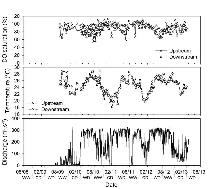
Fig. 11. Evolution of the upstream (DCH2) and downstream (DCH3) oxygen saturation (%), tempera-
ture (°C) and discharges (m3.s-1; from Descloux et al., same issue) with time between 2008 and 2013
at the Downstream channel site.
Fig. 11. Évolution de la saturation en oxygen (%), de la température (°C) et du débit (m3.s-1; après
Descloux et al., même numéro) aux stations amont (DCH2) et aval (DCH3) avec le temps entre 2008
and 2013 au site du Chenal aval.
from 2011, methane is almost absent structures. Upstream of the weir at
from the water body during the WW DCH2, DO saturation levels were always
(2.6 µmol.L-1) and CD (0.7 µmol.L-1) above 52.5% (85.2 in average from
seasons in average (Deshmukh et al., 2009 to 2013) even at the beginning of
submitted). The degassing efficiency the operation phase (Fig. 11), underly-
was very high (e = 0.98; Fig. 8) with no ing the good water quality leaving the
significant differences among the two NT2 Reservoir (Chanudet et al., same
flow classes. issue) and the downstream aeration
efficiency of the baffle blocks at the
3.3 Aeration Weir Regulating Dam and the small aeration
weirs. There was no DO evolution from
DO saturation levels and CH4 con- year to year: there was a seasonal pat-
centrations in the water at the weir site tern with a maximum seasonal saturation
were highly influenced by the upstream level (93.3% in average) during the CDEfficiency of the Nam Theun 2 hydraulic structures on water aeration 19 season and a minimum saturation level tested in this study were able to oxygen- (78.4%) during the WD seasons. The ate waters. The hollow jet valve of WW season presented intermediate the Nam Theun riparian release and DO saturation levels (83.7%). The mean the concrete tooth shaped device of DO apparent gain was therefore low the Nam Kathang release had an (2.3% in average) during the CD season aeration efficiency significantly higher and at 13.3%during the WD season. ( E ′ = 0.91±0.04 and 0.89±0.06 respec- The corresponding overall aeration effi- tively; Fig. 7) than the staggered baffle ciency seems moderate with a higher blocks of the Downstream Channel effect found at low flow ( E ′ = 0.64±0.12; ( E ′ = 0.57±0.04; P
20                                    S. Descloux et al.

time of the air-water exchange (Chanson,              The three devices that were tested
1995; EPRI, 2002; Emiroglu & Baylar,             under contrasting water flows generally
2006). Moreover, to obtain an unbiased           presented a better aeration efficiencies
estimate of the intrinsic efficiency of the      at low flows. This result is consistent
devices, an assessment of the contribu-          with previous studies (Chanson, 1995;
tion of flow stretches between the               Richard et al., 2005) that demonstrated
devices and the downstream measure-              that low flows had higher waterfall, facil-
ment points should have been made                itating the flow to plunge into the water
and it would have been better to test the        body. At low discharges, breakup of the
structure under the entire range of              jet is observed as drop height increases.
upstream conditions (0 to 100% of                High flows decrease the total height of
upstream DO saturations and low to               the Aeration Weir and thus both the
very high CH4 saturations); which has            duration of the air-water exchange and
not been possible to test for the Aeration       the depth of air bubbles driven into the
Weir for instance. Upstream DO satu-             water. The efficiency of a weir was
rations were too close to the saturation         found to be maximum at a tailwater
at this site preventing any measure-             depth of approximate 0.6 times the drop
ment at low DO saturation conditions             height, indicating that a trade-off exists
and thus, it may have artificially under-        between bubble residence time, pres-
estimate the intrinsic efficiency poten-         sure, and turbulence levels (Avery &
tial of the structure (see also Chapter 2.3      Novak, 1978). High flows may also
on uncertainties and calculations).              decrease the turbulences created by
     Our study demonstrates that, for the        the structure (baffle blocks or concrete
range of upstream DO and methane                 tooth) by decreasing the difference of
concentrations tested, aeration effi-            water level between the upstream and
ciency is very high with the hydraulic           the downstream of the structure. At the
systems using the hollow jet valve and           Nam Kathang site, contrary to the other
the concrete tooth, substantial with the         devices, the maximum flow recorded
downstream weir and moderately effi-             during the measurements remained low
cient using the baffle blocks especially         (41 m3.s-1) thus limiting the effect on
at high discharges. Deswal (2009)                downstream water level. The weir
found in a laboratory experiment that            remained moderately efficient for oxy-
DO aeration efficiency of a hollow jet           genation but is less sensitive to the
valve increases with the increase in jet         water discharge due to its optimized
velocity and that this device is compet-         conception. The aerating weir located
itive with other types of aeration sys-          downstream of the Petit Saut Reservoir
tems. At NT2, the hollow jet after pass-         (French Guiana) had an overall aerat-
ing through the atmosphere plunges               ing efficiency close to 0.90 for tur-
into a water pool where substantial              binated discharge up to 200 m3.s–1
amount of air is entrained, leading to a         (Gosse & Gregoire, 1997; Richard et al.,
high air-water interfacial area. At NT2,         2005). The high level of efficiency at
water flow was constant and the overall          high discharge is coming from the
good aeration efficiency was confirmed           design of the weir made of hexagonal
on site.                                         metallic structures with two consecutive
Efficiency of the Nam Theun 2 hydraulic structures on water aeration 21
falls. Other studies from Hauser & and the height of the steps. The higher
Proctor (1993), reported an efficiency the step is, the better the efficiency is.
of the aerating single fall weirs of South Overall stepped cascades were very
Holston and Chatuge around 0.60 and efficient because of the strong turbu-
0.68 respectively and Baylar & Bagatur lence mixing and associated air entrain-
(2000) reported an efficiency of approx- ment and residence time. They also
imately 0.70 for low-head overflow found that aeration efficiency was better
weirs. All of these aeration efficiency at low flow (nappe flow regime).
studies are in accordance with the The hollow jet valve, the concrete
results of our study. tooth structure and the Aerating Weir
Our hypothesis suggesting that baf- demonstrated a very good efficiency in
fle blocks are able to highly aerate the degassing CH4. The baffle blocks struc-
water body was based on the study of ture is moderately efficient in oxygenat-
Kaya & Emiroglu (2010), that have ing and degassing at low and interme-
reported that storm water systems, chan- diate flow discharge and is not efficient
nels and canals commonly use baffle at high flow discharge. Nevertheless,
blocks or baffled chutes for energy dis- flow discharge seems to have less
sipation. They indicated a close rela- effect on CH4 degassing efficiency than
tionship between energy dissipation for aeration for other structures. For
and oxygen transfer efficiency and have instance the CH4 degassing efficiency
shown an effective oxygen transfer. of the concrete tooth structure is equiv-
Johnson (1975), also previously pre- alent whatever the flow discharge.
dicted that flow into a highly baffled Dissolved CH4 concentrations
basin might produce higher aeration than remained high at DCH2 (upstream of
a conventional hydraulic jump basin. the Aeration Weir) and the Aeration
This is not supported by the results of Weir contributed to the elimination of
the monitoring, with the baffle block almost all of the remaining CH4 from the
structure being only moderately effi- water body. The weir installed in March
cient. Contrary to the hollow jet valve, 1995 in the Petit Saut Reservoir, had a
the baffle blocks (and the concrete good degassing efficiency similar to the
tooth) were not designed to have a NT2 Aeration Weir, with close to 80% of
plunging flow increasing the air-water the dissolved CH4 eliminated from the
exchange, which could partially explain turbined water (Richard et al., 2005;
the results. The overall efficiency of the Gregoire & Descloux, 2009).
baffle blocks can be compared to aera- Except for the baffle blocks structure
tion efficiency of natural stepped cas- at high flow discharge, all the hydraulic
cades. Toombes & Chanson (2000) structures of the NT2 Project are able to
reviewed the efficiency of stepped cas- aerate/degas the water body with a
cades mainly located in the USA and good efficiency. These structures have
Emiroglu & Baylar (2006) measured the advantages to be reliable while
aeration efficiency of stepped chutes in requiring low maintenance. The hollow
an experiment. They found aeration jet valve and the concrete tooth struc-
efficiencies close to our study ranging ture are very efficient in aerating/degas-
from 0.50 to 1.00 depending of the flow sing waters but they can be used only22 S. Descloux et al.
for low flows contrary to other structures efficient in aerating/degassing com-
that can be used under a wide range of pared to the staggered baffle blocks. At
flow discharge. the Aeration Weir the DO gain is limited
Thanks to the hydraulic structures, by the high upstream saturation but this
no anoxia/low DO saturations were device is very efficient for methane
observed since the beginning of the degassing, even at low concentrations.
monitoring into the downstream rivers While the DO content could have been
(Chanudet et al., same issue). The spe- good in the Downstream Channel with-
cific design and level of the water out the Aeration Weir, it was obviously
intakes also contribute to improve the useful to eliminate the remaining meth-
water quality of the downstream releases. ane in water. The water quality of the
For instance the Nam Theun River downstream rivers of the NT2 Project
mainly received water from the sub-sur- has always been good since the
face of the reservoir whereas the Down- impoundment of the reservoir thanks to
stream Channel and Nam Kathang the particulate design of the Intake, the
River receive mixed water from the NT2 overall water quality of the reservoir and
Reservoir through the Regulating Pond the aeration of the hydraulic structures
(Chanudet et al., same issue). examined in this study.
These hydraulics structures are an
5 CONCLUSION efficient, reliable and low maintenance
way to improve DO and to degas CH4
The NT2 Reservoir was first at reservoir releases. However the effi-
impounded in 2008. The reservoir expe- ciency of a structure is always a trade-
rienced hypolimnetic deoxygenation off between the energy production loss
and periods of anoxia below the ther- due to the head reduction and the down-
mocline during the first 2 years that were stream water quality requirements.
anticipated with dedicated aerating civil
work structures. The study assessed for ACKNOWLEDGMENTS
the first time the efficiency, on site, of
several dedicated and non-dedicated This research was conducted at the
structures on aeration and CH4 degas- Aquatic Environment Laboratory of Nam
sing. Moreover, the time series allows Theun 2 Power Company in Lao PDR
for a quantification of the evolution of whose Shareholders are Électricité de
these effects with time, taking into France, Lao Holding State Enterprise
account that some civil works were and Electricity Generating Public Com-
tested for a limited range of upstream pany Limited of Thailand.
DO and methane concentrations. With The authors would like to thank the
the improvement of the water quality Nam Theun 2 Power Company (NTPC)
(increase in DO saturation and decrease for providing the logistic support on site
of CH4 contents), the overall aerating related to field activities and the Tech-
and degassing effects of the hydraulics nical Division of NTPC, for providing
structure ranged from very good to mod- key technical drawings. We are also
erate. The hollow jet valve and the con- grateful to the team of the Aquatic Envi-
crete tooth shaped structure were more ronment Laboratory (AEL) for chemistryEfficiency of the Nam Theun 2 hydraulic structures on water aeration 23
analyses and their help during field Nam Theun 2 hydroelectric project (Lao
trips. Finally, we are thankful to Leah PDR) and the associated environmental
Bêche, who reviewed and improved monitoring programme. Hydroécol. Appl.
this version of the manuscript as a (same issue).
native English-speaker. Deshmukh C., Serça D., Delon C., Tardif R.,
Demarty M., Jarnot C., Meyerfeld Y.,
Chanudet V., Guédant P., Rode W.,
Descloux S. & Guérin F. (2014). Physical
REFERENCES controls on CH 4 emissions from a newly
flooded subtropical freshwater hydroe-
Abril G., Guérin F., Richard S., Delmas R., lectric reservoir: Nam Theun 2. Biogeos-
Galy-Lacaux C., Gosse P., Tremblay A., ciences Discussions 11(2), 3271-3317.
Varfalvy L., dos Santos M.A. & Matvienko Deshmukh C., Guérin F., Pighini S.,
B., 2005. Carbon dioxide and methane Vongkhamsao A., Guédant P., Rode W.,
emissions and the carbon budget of a Chanudet V., Descloux S., Godon A. &
10-year old tropical reservoir (Petit Saut, Serça D. Low methane (CH4) emissions
French Guiana). Glob. Biogeochem. downstream a newly flooded subtropical
Cycles 19(4) : 16 p. hydroelectric reservoir in southeast
Avery S.T. & Novak P., 1978. Oxygen Trans- Asia: the Nam Theun 2 Reservoir (Lao
fer at Hydraulic Structures. J. Hyd. Div., PDR). Biogeosciences, submitted.
ASCE 104 : 1521-1540. Deswal S., 2009. Oxygenation by hollow
Baylar A. & Bagatur T., 2000. Study of Aera- plungingwaterjet.J.Instit.Engin.7:40-47.
tion Efficiency at Weirs. Turk J. Engin. DTG, 2012. Rapport : Nakai Reservoir on
Environ. Sci. 24 : 255-264. the Nam Theun River, capacity curve
Baylar A., Kisi O. & Emiroglu M.E., 2009. calculation, 2012 data, Grenoble, 9 p.
Modeling Air Entrainment Rate and Emiroglu M.E. & Baylar A., 2003. Experimen-
Aeration Efficiency of Weirs Using ANN tal Study of the Influence of Different Weir
Approach. G.U. J. Sci. 22(2) : 107-116. Types on the Rate of Air Entrainment.
Chanudet V., Guédant P., Rode W., Godon Water Qual. Res. J. Canada 38 : 769-783.
A., Guérin F., Serça D., Deshmukh C. & Emiroglu M.E. & Baylar A., 2006. Self-aera-
Descloux S., 2015. Evolution of the phy- tion in smooth and stepped chutes. Int. J.
sico-chemical water quality in the Nam Sci.Technol. 1(2) : 105-113.
Theun 2 Reservoir and downstream EPRI (Electric Power Research Institute),
rivers for the first 5 years after impound- 2002. Maintaining and Monitoring Dis-
ment. Hydroécol. Appl. (same issue). solved Oxygen at Hydroelectric Pro-
Chanson H. 1995. Predicting Oxygen jects: Status Report, EPRI Palo Alto, CA:
Content Downstream of Weirs, Spil- 2002 1005194, 194 p.
lways and Waterways. Proc. Instn Civ. Fabre V., Chanudet V. & Bellet L., 2010.
Engrs Wat. Marit. & Energy, UK, Vol. Results of the velocity measurements on
112, Mar., pp. 20-30 (ISSN 0965-0946). the Nam Theun 2 reservoir, EDF report
Descloux S., Chanudet V., Poilvé H. & IH.NT-WQ.ENV.00041A, 25 p.
Grégoire A., 2011. Coassesment of bio- Galy-Lacaux C., Delmas R., Jambert C.,
mass and soil organic carbon stocks in a Dumestre J.F., Labroue L., Richard S. &
future reservoir located in Southern Asia. Gosse P., 1997. Gaseous emissions and
Environ. Monit. Assess. 173 : 723-741. oxygen consumption in hydroelectric
Descloux S., Guedant P., Phommachanh D. dams: A case study in French Guyana.
& Luthi R., 2015. Main features of the Glob. Biogeochem. Cycles 11 : 471-483.24 S. Descloux et al.
Galy-Lacaux C., Delmas R., Kouadio G., chutes. Proceedings of the ICE - Water
Richard S. & Gosse P., 1999. Long-term Management, Vol. 163, Issue 9, July
greenhouse gas emissions from hydroe- 2010, pp. 447-456.
lectric reservoirs in tropical forest regions. Kutty M.N., 1972. Respiratory quotient and
Glob. Biogeochem. Cycles 13 : 503-517. ammonia excretion in Tilapia mossam-
Gameson A., Vandyke K. & Ogden C., 1958. bica. Marine Biology 16(2) : 126-133.
The effect of temperature on aeration at
Kutty M.N., & Saunders R.L., 1973. Swim-
weirs. Water Engineering 62.
ming performance of young Atlantic sal-
Gosse P. & Gregoire A., 1997. Dispositif de mon (Salmo salar) as affected by
réoxygénation artificielle du Sinnamary reduced ambient oxygen concentration.
à l’aval du barrage de Petit-Saut Journal of the Fisheries Board of
(Guyane). Hydroécol. Appl. 9 : 23-56. Canada 30(2) : 223-227.
Gosse P., Sabaton S., Travade F. & Eon J.,
Patin S., 1999. Environmental impact of the
1997. EDF experience in improving reser-
offshore oil and gas industry. Economi-
voir releases for ecological purposes.
tor Publication 448.
Water for a changing global community.
Energy and Water: Sustainable Develop- R Development Core Team, 2009. A lan-
ment. In: Holly M. & Alsaffar A. (Eds.), 452- guage and environment for statistical
458, Am. Soc. Civ. Eng., New-York, 1997. computing. R Foundation for statistical
computing, Vienna, Austria.
Gregoire A. & Descloux S., 2009. Advan-
tages and disadvantages of an aerating Richard S., Gregoire A. & Gosse P., 2005.
weir in a tropical zone. Verh. Internat. The efficiency of an artificial weir in oxy-
Verein. Limnol. 30 : 850-853. genating and removing CH4 from water
Guérin F., Abril G., de Junet A., & Bonnet released by the Petit Saut hydroelectric
M.-P., 2008. Anaerobic decomposition of dam (French Guiana). Revue des
tropical soils and plant material: Implica- Sciences de l’Eau 18 : 127-141.
tion for the CO2 and CH4 budget of the Sackett W.M. & Brooks J.M., 1975. Origin and
Petit Saut Reservoir. Appl. Geochem. distributions of low molecular weight
23 : 2272-2283. hydrocarbons in Gulf of Mexico coastal
Gulliver J.S., Wilhelms S.C. & Parkhill K.L., waters. In: Church T.M. (Ed.), Marine
1998. Predictive capabilities in oxygen Chemistry in the Coastal Environment,
transfer at hydraulic structures. J. Am. Chem. Soc. Symp. Ser., 18, pp. 211-
hydraulic Engin. 124(7) : 664-671. 230.
Hauser G. & Proctor G., 1993. Performance Toombes L. & Chanson H., 2000. Air-water
of prototype aerating weirs downstream flow and gas transfer at aeration cas-
from TVA Hydropower dams. Proc. Natl. cades: A comparative study of smooth
Conf. Hydraul. Eng. San Francisco. and stepped chutes. Hydraulics of Step-
ASCE, p. 99. ped Spillways, In: Minor and Hager
Johnson P.L., 1975. Prediction of Dissolved (Eds.), 2000, Balkema, Rotterdam, ISBN
Gas at Hydraulic Structures. Enginee- 905809 135X.
ring and Research Center Bureau of Townsend S.A., 1999. The seasonal pattern
Reclamation Denver, Colorado 80225, of dissolved oxygen, and hypolimnetic
Report GR-8-75, 78 p. deoxygenation, in two tropical Australian
Kaya N. & Emiroglu M.E., 2010. Study of reservoirs. Lakes & Reservoirs: Research
oxygen transfer efficiency at baffled & Management 4 : 41-53.You can also read