Electrical percolation in extrinsically conducting, poly(ε decalactone) composite neural interface materials - Nature
←
→
Page content transcription
If your browser does not render page correctly, please read the page content below

www.nature.com/scientificreports
OPEN Electrical percolation
in extrinsically conducting,
poly(ε‑decalactone) composite
neural interface materials
Katarzyna Krukiewicz1,2*, James Britton1, Daria Więcławska2, Małgorzata Skorupa2,
Jorge Fernandez3,4, Jose‑Ramon Sarasua3 & Manus J. P. Biggs1
By providing a bidirectional communication channel between neural tissues and a biomedical
device, it is envisaged that neural interfaces will be fundamental in the future diagnosis and
treatment of neurological disorders. Due to the mechanical mismatch between neural tissue and
metallic neural electrodes, soft electrically conducting materials are of great benefit in promoting
chronic device functionality. In this study, carbon nanotubes (CNT), silver nanowires (AgNW) and
poly(hydroxymethyl 3,4-ethylenedioxythiophene) microspheres (MSP) were employed as conducting
fillers within a poly(ε-decalactone) (EDL) matrix, to form a soft and electrically conducting composite.
The effect of a filler type on the electrical percolation threshold, and composite biocompatibility was
investigated in vitro. EDL-based composites exhibited favourable electrochemical characteristics:
EDL/CNT—the lowest film resistance (1.2 ± 0.3 kΩ), EDL/AgNW—the highest charge storage capacity
(10.7 ± 0.3 mC cm− 2), and EDL/MSP—the highest interphase capacitance (1478.4 ± 92.4 µF cm−2).
All investigated composite surfaces were found to be biocompatible, and to reduce the presence of
reactive astrocytes relative to control electrodes. The results of this work clearly demonstrated the
ability of high aspect ratio structures to form an extended percolation network within a polyester
matrix, resulting in the formulation of composites with advantageous mechanical, electrochemical
and biocompatibility properties.
Neural interfaces typically consist of an array of planar or micro-wire electrodes, implanted onto or into tissues
of the central or peripheral nervous system. By providing a bidirectional communication channel between neural
tissues and a biomedical device, it is envisaged that neural interfaces will be fundamental in the future diagnosis
and treatment of neurological d isorders1. Traditionally, neural interfaces are made of noble metals, particu-
larly platinum and gold, combining high electrical conductivity with moderate biocompatibility. Nevertheless,
due to the mechanical mismatch between the stiff metal surface and excitable tissues, implantable interfacing
electrodes illicit an inflammatory response which restricts chronic functionality in vivo2. Ongoing efforts to
mitigate this problem include employing soft biocompatible polymers with favorable electrical properties as
biointerfacing electrodes3. In particular, hydrogel formulations including poly(ethylene glycol)4, and poly(N-
isopropylacrylamide) microgels5 have been explored extensively as neuroelectrode coatings. Even though these
materials are known for their biomimetic mechanical properties, their ability to enhance neuronal survival, and
to improve tissue responses at the peri-electrode interface, they are not intrinsically electrically conducting. A
further promising group of compounds that is devoid of this drawback and have been explored extensively as
neural electrode coatings comprises intrinsically conducting polymers6. Although possessing high conductivity
and good biocompatibility, conducting polymers are associated with electromechanical instability and increased
mechanical stiffness relative to hydrogel f ormulations7.
1
Centre for Research in Medical Devices, National University of Ireland, Newcastle Road, Galway H91 W2TY,
Ireland. 2Department of Physical Chemistry and Technology of Polymers, Silesian University of Technology,
M.Strzody 9, 44‑100 Gliwice, Poland. 3Department of Mining‑Metallurgy Engineering and Materials Science,
School of Engineering, POLYMAT, University of the Basque Country (UPV/EHU), Alameda de Urquijo s/n,
48013 Bilbao, Spain. 4Polimerbio, S.L, Paseo Mikeletegi 83, 20009 Donostia‑San Sebastian, Spain. *email:
katarzyna.krukiewicz@polsl.pl
Scientific Reports | (2021) 11:1295 | https://doi.org/10.1038/s41598-020-80361-7 1
Vol.:(0123456789)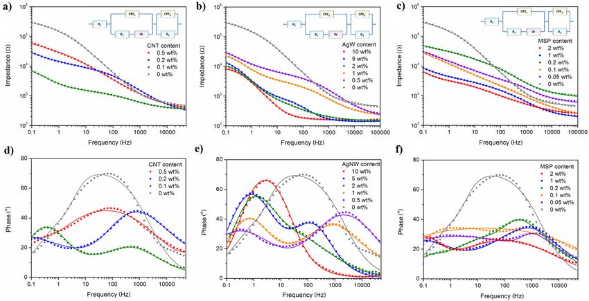
www.nature.com/scientificreports/
Figure 1. Surface characterization of EDL-based composites. SEM micrographs of EDL/CNT (a), EDL/AgNW
(b) and EDL/MSP (c), the latter with the inset showing P(EDOT-OH) microspheres after synthesis.
To avail of their outstanding biocompatibility, non-conducting elastomeric biomaterials can be used as matri-
ces for conducting fillers to produce both conducting and biocompatible composite coatings, which negate the
negative effects of the fillers on cell viability and proliferation8. So far, several reports have described the design of
composite materials of polyurethane and carbon n anotubes9, polydimethylsiloxane and carbon n anotubes10, poly-
lactide and polyaniline11, or more sophisticated, three-composite materials made of carbon nanotubes, polypyr-
role and poly(ethylene glycol) diacrylate p olyacrylamide12. In our studies, an aliphatic polyester was chosen as a
biocompatible matrix. Poly(ε-decalactone) (EDL), is a soft elastomeric material possessing high biocompatibility,
desirable mechanical properties, and is derived from an environmentally sustainable synthesis p rocess13. To
endow the polymer with electrical conducting properties, the polymer matrix was loaded with selected fillers
differing in size and shape, namely carbon nanotubes (CNT), silver nanowires (AgNW) and conducting polymer
microspheres (MSP). The selection of fillers was based on their conductivity as well as the ability to interact with
neurons. As described by Sorkin et al.14, neural cells are able to directly attach to CNT, and the entanglement
of cellular processes can be easily observed on CNT-modified surfaces. Indeed, curly nature of CNT network
was found to improve neuronal adhesion, and enhance interactions between CNT and neural cells. The similar
observation was made for conducting polymers, particularly PEDOT, which were found to increase the action
potentials of PC12 cells as a response to external electrical stimulation15, as well as to stimulate retinal neurons at
low voltage amplitudes and low charge densities16. In our previous study13, we described neural cell stimulation
experiments confirming that AgNW are able to transfer charges suitable for cellular depolarization, increasing
stimulation efficiency when compared with a control electrode. To determine the minimum amount of a filler
required to provide a favourable conductive profile to the polyester matrix, electrochemical impedance spectra
(EIS) and cyclic voltammograms (CV) of EDL-based composites were recorded, and the corresponding values
of film resistance, capacitance (C) and charge storage capacity (CSC) were extracted. The morphology of the
material-tissue interface was examined using scanning electron microscopy to visualize percolation network of
filler particles. Finally, the biocompatibility of the composites was assessed in vitro using ventral mesencephalon
(VM) cells derived from embryonic rat brain tissue.
Results
Surface morphology. The presence of each filler on the surface morphology of EDL-based composites was
assessed by SEM imaging, as shown in Fig. 1. In the case of EDL/CNT nanocomposites (Fig. 1a), the surface
morphology was characterised by the presence of non-uniform elongated protrusions with a length between
1.5 μm and 5 μm, and a width between 50 to 400 nm, significantly larger than the dimensions of the filler CNT
(outer diameter of 10 nm, inner diameter of 4.5 nm, length of 3–6 μm). The presence of surface filler particles
was also evident in EDL/AgNW nanocomposite materials (Fig. 1b). Interestingly, AgNW nanowires protruded
from the composite surface, with a fraction of these demonstrating deformation. The morphology of EDL/MSP
composites (Fig. 1c) was characterised by a rough surface of nodules possessing an average diameter of 2 µm,
four times higher than the diameter of individual MSP (0.5 µm, Fig. 1c-inset).
Electrochemical characterisation. Electrochemical behaviour of EDL/CNT, EDL/AgNW and EDL/MSP
composites was assessed by electrochemical impedance spectroscopy (Fig. 2) and cyclic voltammetry (Fig. 3),
and the results were used to evaluate the mean film resistance, capacitance and charge storage capacity (CSC)
of each material (Fig. 4). For both EDL/AgNW and EDL/MSP, an increase in a filler content led to a decrease
in the impedance of the material over the whole frequency range employed (Fig. 2b,c). In contrast, EDL/CNT
formulations (Fig. 2a), demonstrated the lowest impedance profile with a 0.1 wt% CNT content. Similarly, the
phase profile of EDL/CNT formulations (Fig. 2d) containing 0.1 wt% CNT content differed significantly from
the phase profile of pristine EDL, showing two distinct phase angle peaks (0.4 Hz ad 450 Hz), in opposition to a
single phase angle peak at the frequency of ~ 70 Hz observed for pristine EDL. A similar two-peak phase angle
profile was observed for EDL/MSP (Fig. 2f), with phase peaks noted at the frequencies of 0.15 Hz and 75 Hz.
In the case of EDL/AgNW (Fig. 2e), a two-peak phase angle profile was observed for composite formulations
with 0.5–5 wt% AgNW content. When the AgNW content was increased to 10 wt%, a single phase peak could
be observed at the frequency of 3 Hz.
An increase in the area under the CV curve with no defined indication of reduction/oxidation peaks was
observed for EDL/CNT (Fig. 3a), particularly for a composite formulated with 0.1 wt% CNT content. Conversely,
Scientific Reports | (2021) 11:1295 | https://doi.org/10.1038/s41598-020-80361-7 2
Vol:.(1234567890)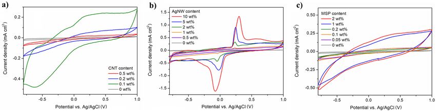
www.nature.com/scientificreports/
Figure 2. Electrochemical impedance spectroscopy study of EDL-based composites. Bode plots showing
the frequency-dependent behaviour of the impedance modulus of EDL/CNT (a), EDL/AgNW (b) and EDL/
MSP (c), and phase angle of EDL/CNT (d), EDL/AgNW (e) and EDL/MSP (f) composites; dots represent
experimental data, while lines represent simulated results; equivalent circuit models used for the fitting of EIS
data are presented as the insets. EIS data were collected in 0.1 M KCl solution, in the frequency range from
0.1 Hz to 100 kHz, with an AC amplitude of 40 mV (vs. Ag/AgCl) and a DC potential equal to 0 V (vs. Ag/
AgCl). EIS simulations were performed by means of EIS Spectrum Analyzer 1.0 software (http://www.abc.chemi
stry.bsu.by/vi/analyser/).
Figure 3. Electrochemical behaviour of EDL-based composites. Cyclic voltammetric curves of EDL/CNT
(a), EDL/AgNW (b) and EDL/MSP (c) composites collected in 0.1 M KCl solution within the potential range
from − 0.8 to 1.0 V (vs. Ag/AgCl) at 100 mV s−1.
the CV curves of EDL/AgNW nanocomposites (Fig. 3b) were characterized by a distinctive reduction–oxidation
system at the potentials of − 0.05 V (reduction of silver) and 0.25 V (oxidation of silver), appearing for composites
with AgNW contents above 0.5 wt%. With an increase in AgNW content, an increase in the peak current was
observed, accompanied by a small increase in peak separation (from 270 mV for EDL/AgNW 1 wt% to 380 mV
for EDL/AgNW 10 wt%). Conversely, an increase in the area under the CV curve with no defined indication of
reduction/oxidation peaks was observed for EDL/MSP (Fig. 3c), starting from an MSP content of 1 wt%.
By integrating CV curves in the time domain, the charge storage capacities (CSC) of EDL composites were
calculated and compared with capacitances and resistances determined from the equivalent circuit modelling
of the EIS data (Fig. 4a–c). One of the most common models is a Randles circuit, which is frequently used to
simulate electrode–electrolyte interface impedance of coated electrodes17. For the purpose of modelling, a modi-
fied Randles circuit was used, including a solution resistance (R1), charge transfer resistance (R2), constant phase
element modeling the non-faradaic processes (CPE1), Warburg element representing the finite length diffusion
of faradaic current (W), resistance to charge conduction in the solid electrolyte interphase layer (film resistance,
Scientific Reports | (2021) 11:1295 | https://doi.org/10.1038/s41598-020-80361-7 3
Vol.:(0123456789)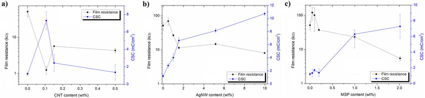
www.nature.com/scientificreports/
Figure 4. Electrochemical percolation threshold for EDL-based composites. Film resistance/charge storage
capacity (CSC) plots of EDL/CNT (a), EDL/AgNW (b) and EDL/MSP (c) composites; n = 3. Film resistance
values were determined using an equivalent circuit modelling of EIS data ( R3), while CSC values were calculated
from CV curves.
Circuit element EDL EDL/CNT 0.1 wt% EDL/AgNW 2 wt% EDL/MSP 2 wt%
Solution resistance (R1), Ω 465 338 146 208
Charge transfer resistance (R2), Ω 296,000 2450 643 4417
Resistance in the solid electrolyte interphase layer (R3), Ω 51,464 1242 11,483 5483
CPE parameter (P1), µS sn 2.1 161.1 134.0 63.8
CPE parameter (n1) 0.733 0.751 0.533 0.432
Capacitance of non-faradaic processes (C1), µF 1.8 119.0 15.6 12.2
CPE parameter (P2), µS sn 0.9 20.8 67.8 416.4
CPE parameter (n2) 1.000 0.558 0.884 0.993
Capacitance of interphase layer (C2), µF 0.9 1.2 65.6 418.4
Warburg coefficient (Wsr1), pΩ s−1/2 0.19 0.25 7.41 0.97
Warburg parameter (Wsc1) 0.7 7.9 8.7 8.7
% deviation (χ) 9.1 1.8 2.9 1.8
Table 1. Representative set of electrical parameters derived from an equivalent circuit modelling of EIS data
for pristine EDL, EDL/CNT 0.1 wt%, EDL/AgNW 2 wt% and EDL/MSP 2 wt%.
R3) and charge capacitance of interphase layer ( CPE2)18, with the quality of fitting demonstrated by the fitted
curves in the Bode plots (Fig. 2a–f) and low percentage deviation between experimental data and fitted values
(Table 1). Among all samples, the highest value of CSC (10.7 ± 0.3 mC c m−2) was noted for EDL/AgNW (10
wt%), and the lowest value of film resistance (1.2 ± 0.3 kΩ) was noted for EDL/CNT (0.1 wt%). Further increases
in the CNT content did not increase the CSC or decrease the film resistance of EDL/CNT nanocomposites,
but had a deteriorating effect on their electrochemical behaviour. Conversely, for both EDL/AgNW and EDL/
MSP composite materials, increases in the filler content led to enhancement of the electrochemical properties.
Although the percolation threshold for EDL/AgNW was observed at 2 wt% content (CSC of 6.6 ± 0.4 mC c m−2,
film resistance of 11.5 ± 0.6 kΩ), further increases in the AgNW content increased the CSC to a maximum of
10.7 ± 0.3 mC cm−2 and decreased the film resistance to a minimum of 8.1 ± 0.3 kΩ for EDL/AgNW (10 wt%).
For EDL/MSP composites, the percolation threshold was also observed at 2 wt% MSP content, resulting in a
CSC of 7.3 ± 1.5 mC cm−2 and a film resistance of 5.5 ± 0.8 kΩ.
The comparison of electrical parameters derived from an equivalent circuit modelling of EIS data for repre-
sentative EDL-based composites (Table 1) further highlighted the effect of the presence of particular conduct-
ing fillers on the electrochemical properties of fabricated materials. Charge transfer resistance was found to
dramatically decrease when EDL matrix (296 kΩ) was filled with either CNT (2 450 Ω), AgNW (643 Ω) or MSP
(4 417 Ω). The similar behaviour was observed for the resistance in the solid electrolyte interphase layer (film
resistance, R3), which was found to decrease from 5 to 50 times for EDL/AgNW and EDL/CNT, respectively. The
improvement was also observed in the capacitive behaviour of the composites, indicating EDL/CNT as having
the highest capacitance of non-faradaic processes (119.0 µF), and EDL/MSP as exhibiting the highest interphase
capacitance (418.4 µF). A high variation of Warburg parameters, particularly Wsc, between pristine EDL and
EDL-based composites indicated limited diffusion of faradaic current observed for pristine polymer, and the
similar diffusive behaviour of all EDL-based composite materials.
For the subsequent biological characterization, EDL-based composites with the filler content above percola-
tion threshold were chosen, exhibiting the electrical properties summarized in Table 2.
In vitro biocompatibility. The cytocompatibility of EDL-based composites was assessed with respect to
a mixed neural population obtained from ventral mesencephalon (VM) of embryonic Sprague–Dawley rats.
Scientific Reports | (2021) 11:1295 | https://doi.org/10.1038/s41598-020-80361-7 4
Vol:.(1234567890)www.nature.com/scientificreports/
Parameter EDL EDL/CNT 0.1 wt% EDL/AgNW 2 wt% EDL/MSP 2 wt%
Film resistance, kΩ 51.4 ± 14.1 1.2 ± 0.3 11.5 ± 0.6 5.5 ± 0.8
Charge storage capacity (CSC), mC cm−2 1.2 ± 0.2 6.3 ± 1.0 6.6 ± 0.4 7.3 ± 1.5
Areal capacitance of non-faradaic processes, µF cm−2 6.4 ± 1,4 420.5 ± 12.6 55.1 ± 1.7 43.1 ± 2.6
Areal capacitance of interphase layer (C2), µF cm−2 3.2 ± 0.7 4.2 ± 0.2 231.8 ± 6.3 1478.4 ± 92.4
Table 2. Summary of electrical parameters of pristine EDL, EDL/CNT 0.1 wt%, EDL/AgNW 2 wt% and EDL/
MSP 2 wt%.
Figure 5. Biocompatibility of EDL-based composites. Fluorescent images of primary ventral mesencephalic
mixed cell population cultured for 3, 7 and 14 days on a control substrate (bare Pt-coated glass slide), pristine
EDL, EDL/CNT, EDL/AgNW and EDL/MSP; neurons are visualized by anti β-tubulin III (red), astrocyte cells
by anti-GFAP (green) and nuclei by DAPI (blue); the scale bar represents 20 μm (a). Cell density (%) analysis of
astrocyte and neuron presence on each of the experimental and control group (b); n = 3, * = p < 0.05.
Scientific Reports | (2021) 11:1295 | https://doi.org/10.1038/s41598-020-80361-7 5
Vol.:(0123456789)www.nature.com/scientificreports/
VM cells were cultured on the surface of all experimental composite and control materials for 3, 7 and 14 days
in vitro, and were visualized by dual immuno-staining to distinguish neurons and astrocytes (Fig. 5a). Fur-
ther quantification was conducted to extract the percentage of neurons and astrocytes present on each of the
experimental composites and control substrates (Pt and EDL coated glass slides) (Fig. 5b). At each time point,
EDL-based coatings were observed to favour the presence of neurons over astrocytes with respect to Pt control
substrates. After 3 days, the percentage of neurons was highest on EDL (80.6 ± 4.0%), EDL/CNT (83.8 ± 0.7%)
and EDL/MSP (88.7 ± 1.0%), a trend maintained at all experimental time points. Although by day 14 the per-
centage of cells cultured on pristine EDL coatings (57.7 ± 4.5%) was not found to differ significantly from cells
cultured on Pt control substrates (51.2 ± 3.4%), all EDL-based composites were observed to lead to an increase
in the presence of neurons relative to astrocyte cells, achieving a neuron distribution percentage of 64.0 ± 6.2%,
68.4 ± 2.0% and 67.7 ± 4.9% for EDL/CNT, EDL/AgNW and EDL/MSP, respectively.
Discussion
Materials employed as neural interfaces should possess high electrical conductivity and cytocompatibility with
biomimetic mechanical properties. To meet these requirements, we described a group of composite materials
consisting of poly(ε-decalactone) (EDL) as a soft and biocompatible polymer matrix, and electrically conduct-
ing fillers, namely multi-walled carbon nanotubes (CNT), silver nanowires (AgNW) and poly(hydroxymethyl
3,4-ethylenedioxythiophene) microspheres (MSP). EDL, a polymer derived from a commercially available,
renewable ε-decalactone, has been recently described as an effective neural interface material, possessing favour-
able mechanical properties and enhancing neurite outgrowth in vitro13. Due to its viscous nature, EDL can be
easily used in simple coating processes, such as dip- and spin-coating. Critically, however, EDL is not an intrinsi-
cally electrically conducting polymer. To promote conductivity, a highly conductive filler must be added to the
EDL polymer matrix, to form a three dimensional network of filler particles, known as a percolation network.
At a particular concentration of the filler, a dramatic increase in conductivity and capacitance of a composite is
observed. This so-called percolation threshold is highly dependent on the aspect ratio of the filler particles, and
is usually observed between 0.05 and 10 wt%19.
Among the three fillers investigated in this study, CNT are the most frequently used for neural applications,
mainly because of their extraordinary strength, electrical conductivity and chemical stability20. Nanocomposites
of polymers with CNT exhibit high charge injection limits and low impedance20, and promote cell viability21,
however the electrical percolation threshold of CNT nanocomposites has been reported to vary considerably.
Specifically, a percolation threshold was obtained at 0.5 wt% CNT content with a polyhydroxyalkanoate matrix21,
1–5 wt% CNT content with a chitin m atrix22, and 18 wt% CNT content with a polyethyleneimine m atrix23. In
this study, we noted a low percolation threshold of 0.1 wt% for CNT characterized by an aspect ratio (length-to-
width) of 450 and conductivity of 35 S c m−1 24. Surprisingly, when the content of CNT was further increased, an
increase in the EDL nanocomposite film resistance and a decrease in CSC were observed, suggesting that above
this CNT content interactions between EDL and CNT, probably derived from a viscous nature of EDL, facilitate
the formation of CNT agglomerates, suppressing the development of a robust percolation network. With a CNT
content of 0.1 wt%, the value of film resistance (1.2 ± 0.3 kΩ) was the lowest among all composites investigated
in this study, irrespective of the amount of filler content. EDL/CNT composites were also found to be highly
capacitive, particularly in terms of the capacitance of non-faradaic processes (420 µF cm−2), associated with the
redistribution of charges at the surface of CNT. Although materials with high capacitances are generally desired
in the design of neural electrodes, they are not favourable for rapid electrochemical measurements, since high
capacitance limits the response time of the d evice25. To allow the use of fast scan rates, the capacitance of the
−2
electrode should be of ∼ 100 μF cm , which is four times lower than noted for EDL/CNT.
EDL composites formulated from a AgNW filler (aspect ratio of 1500, conductivity of 6.3 × 10⁷ S m−1) were
found to possess a percolation threshold at 2 wt% content. Although this value was within a range previously
identified for similar AgNW composite materials26, it was significantly higher than a percolation threshold
noted for EDL/CNT composites. It is hypothesised that this increase is related to the filler density: 10.49 g cm−3
for Ag and 1.6 g cm−3 for CNT. Consequently, the same wt% of each filler should result in a 6.5 × increase in
the volume of CNTs in the EDL matrix relative to AgNW, facilitating the formation of a more robust CNT
percolation network. Conversely, the substantial length and ductility of the AgNWs facilitated a decrease in
film resistance of EDL/AgNW composites with increased AgNW content, up to 8.1 ± 0.3 kΩ. CSC is an impor-
tant consideration in neuroelectrode fabrication and can be used to predict how much charge can be injected
through an electrode during electrical stimulation. Although demonstrating a moderate conductivity, EDL/
AgNW nanocomposites exhibited the highest CSC (10.7 ± 0.3 mC c m−2) of all investigated composites, as well
as other neural electrode materials described in the literature, including PEDOT (~ 7 mC cm−2)27, and PEDOT-
CNT composites (~ 8.6 mC cm−2)28. Due to the electrochemical behaviour of AgNW, which undergo reduction/
oxidation reactions29, a substantial amount of charge (linearly dependent on the concentration of AgNW) is
transferred between the electrode and AgNW, giving rise to the redox system of peaks clearly observed in
the CV curves. Furthermore, the presence of an additional capacitive peak at low frequencies in the phase
angle profile of EDL/AgNW composites confirmed the capacitive nature of this material30. Therefore, EDL/
AgNW was found to exhibit relatively high interphase capacitance (231.8 ± 6.3 µF cm−2) together with moder-
ate capacitance of non-faradaic processes (55.1 ± 1.7 µF cm−2), behaving similarly as Kevlar/graphene oxide
electrodes31. The moderate value of capacitance allows to keep the time needed to charge and discharge the
electrode low, enabling to use fast scans for neural recording and to minimize background c urrents32. Although
pristine conducting polymer electrode coatings exhibit excellent electrochemical properties, EDL composites
formulated with P(EDOT-OH) MSP performed similarly as EDL loaded with CNT or AgNW nanocomposites.
The film resistance of EDL/MSP composites (5.5 ± 0.8 kΩ) was lower than that observed for the EDL/AgNW
Scientific Reports | (2021) 11:1295 | https://doi.org/10.1038/s41598-020-80361-7 6
Vol:.(1234567890)www.nature.com/scientificreports/
nanocomposites, but CSC of 7.3 ± 1.5 mC cm−2 was noted to be lower than CSC of EDL/AgNW, and comparable
with the CSC value of EDL/CNT. Interestingly, EDL/MSP were found to exhibit the highest areal interphase
capacitance (1478.4 ± 92.4 µF cm−2), which should be associated with the processes of charging/discharging of
the electrode–electrolyte double layer, as indicated by the presence of a CV curve typical for P EDOT33. High
interphase capacitance should be derived from the favourable geometry of MSP (aspect ratio of 1), which allows
for maximizing the surface-area-to-volume ratio.
The results of biological investigations confirmed that EDL-based composites promoted neuron and astrocyte
adhesion and viability, irrespective of the filler type. At early time points (3 days), pristine EDL and EDL/CNT
and EDL/MSP composites exhibited an increased presence of neurons relative to a control Pt surface. A similar
trend was observed at day 7. Following 14 days in culture, EDL-coated surfaces possessed a similar neuron/
astrocyte coverage to control Pt substrates. Conversely, all investigated composites significantly increased the
presence of neurons at 14 days of culture. Astrocytes are supporting cells that are present in a healthy neural
population and it is accepted that they play a role in the modulation of neural s ignalling34. Moreover, astrocytes
are known to play an active role in g liosis35, a critical mediator of neural interface failure in vivo. Here, EDL-
based composites were found to reduce astrocyte surface coverage while maintaining a high neuronal coverage,
indicating that they may enhance neuron-electrode coupling and suppress the formation of glial scarring in vivo.
Conclusions
In this study, the effects of carbon nanotubes (CNT), silver nanowires (AgNW) and P(EDOT-OH) microspheres
(MSP) conducting fillers on the electrical percolation threshold and performance of a neural interface material
based on a biocompatible poly(ε-decalactone) matrix were investigated. Due to the geometrical shape of fillers,
ranging from spherical (MSP) to high aspect ratio (CNT, AgNW) structures, the percolation threshold was found
to vary between 0.1 wt% (EDL/CNT) and 2 wt% (EDL/AgNW and EDL/MSP). The most favourable electrical
characteristics in terms of low film resistance (1.2 ± 0.3 kΩ) and high CSC (10.7 ± 0.3 mC cm−2) was noted for
EDL/CNT and EDL/AgNW nanocomposites, respectively. Conversely, the electrical performance of EDL/MSP
was in the range of applicability, but due to the high value of interphase capacitance (1478.4 ± 92.4 µF cm−2) this
composite seemed not to be favourable for rapid electrochemical measurements. All investigated composites
were found to be cytocompatible, and reduced the surface astrocyte load in vitro, which may enhance neuron-
electrode coupling and suppress the formation of a peri-interface glial scar in vivo. The results of our work
clearly demonstrated the potency of selected fillers, CNT and AgNW, to form an extended percolation network
within the matrix of an environmentally sustainable polyester, EDL, resulting in advantageous electrochemical
properties while maintaining a high cytocompatibility. In conclusion, EDL-based conducting composites were
shown to serve as advantageous neural interface materials in vitro.
Methods
Synthesis and characterization of poly(ε‑decalactone). Poly(ε-decalactone) (EDL) was synthesized
according to a method described previously13. In short, after purging ε-decalactone (> 99%, Sigma Aldrich) with
nitrogen, it was mixed with the catalyst ( Ph3Bi, Gelest) at 100:1 monomer/catalyst molar ratio and stirred for
7 days. After this time, the product was dissolved in chloroform, precipitated, dried at room temperature and
heated to ensure the complete elimination of any remaining solvent.
Fabrication of P(EDOT‑OH) microspheres. Poly(hydroxymethyl 3,4-ethylenedioxythiophene) hollow
microspheres (MSP) were fabricated using a sacrificial template chemical polymerisation p rocess36. In brief,
EDOT-OH was dissociated in a sonication bath at a frequency of 35 kHz for 30 min. Following this, polystyrene
(PS) beads with an average diameter of 500 nm (Spherotech inc., CHI, USA) were added to the EDOT-OH solu-
tion to a final concentration of 2.5 mg ml−1. The mixture was allowed to homogenise using a magnetic stirrer
for 30 min before ammonium persulphate was added to initiate polymerisation of EDOT-OH around PS bead
templates. The solution was then mixed for 16 h at room temperature before the addition of excess methanol
ceased the reaction. Following this, the solution was centrifuged (Thermo Scientific HERAEUS FRESCO 17
Centrifuge) at 13,000 rpm for 15 min to remove excess neutralised solution, and washed three times with deion-
ized water by resuspension and repetitive centrifugation. To dissolve the internal polystyrene template, MSP
were suspended in tetrahydrofuran, THF (Sigma Aldrich) for 15 min followed by repetitive washing in deion-
ized water as described earlier.
Fabrication of composites. 100 mg of EDL and 1 ml of THF (Sigma Aldrich) were mixed, heated to 40 °C
and stirred until dissolution. Then, filler particles: silver nanowires (ACS Material, average diameter 100 nm,
average length 100–200 μm, silver purity ~ 99.5%, 20 mg ml−1), multi-walled carbon nanotubes (Sigma Aldrich,
4.5 nm inner diameter, 10 nm outer diameter, 3–6 µm length) or P(EDOT-OH) microspheres (0.5 µm diam-
eter), respectively, were added to the EDL/THF solution, to give a dispersion with the filler weight ratio from
0.05 wt% to 10 wt%. The dispersion was then mixed via ultrasonication (SONICS Sonicator, 40% amplitude,
3.5 MJ, pulsing: 5 s on and 2 s off) for 1 min. Prior to the deposition of a coating, microscopic glass slides
(2.5 × 2.5 × 0.1 cm) were sputter-coated (Emitech K650XT Sputter Coater, 25 mA, 1 × 10− 3 mbar, 180 s) with a
thin layer of Pt (approx. 5 nm). Pristine EDL, EDL/CNT, EDL/AgNW and EDL/MSP coatings were deposited
through a spin coating process (Laurell Technologies Spin Coater) of 0.2 ml of relevant dispersion for 20 s with
a speed of 3000 rpm. After this, coated glass slides were dried for 1 h at 50 °C to evaporate the residual THF.
Homogeneous and uniform coating (5.8 ± 0.8 μm) was formed when EDL concentration was equal to 10 wt%.
Scientific Reports | (2021) 11:1295 | https://doi.org/10.1038/s41598-020-80361-7 7
Vol.:(0123456789)www.nature.com/scientificreports/
Characterization of composites. The surface morphology of EDL/CNT, EDL/AgNW and EDL/MSP
coatings was analysed with scanning electron microscopy (Hitachi S-4700 Scanning Electron Microscope,
15 kV). Electrochemical characterization of pristine EDL, EDL/CNT, EDL/AgNW and EDL/MSP coatings was
performed by means of a PARSTAT 2273 potentiostat in a three-electrode set-up, comprising Ag/AgCl as a
reference electrode, glassy carbon rod as an auxiliary electrode and coated glass slides as a working electrode
(exposed area of 0.283 cm2). Charge storage capacity (CSC) was calculated from the area below cyclic voltam-
metric (CV) curves collected in 0.1 M KCl solution, within the potential range from − 0.8 to 1.0 V (vs. Ag/
AgCl) at 100 mV s−1. Electrical parameters of coatings were calculated basing on the equivalent circuit model-
ling of electrochemical impedance spectra (EIS) collected in 0.1 M KCl solution with frequencies ranging from
100 MHz to 100 kHz, an AC amplitude of 40 mV (vs. Ag/AgCl) and a DC potential equal to 0 V (vs. Ag/AgCl).
The experimental EIS data were fitted to a selected equivalent circuit model (modified Randles circuit) with the
use of an EIS Spectrum Analyzer 1.0 software (http://www.abc.chemistry.bsu.by/vi/analyser/)37. A Powell algo-
rithm was used to fit the data, and the fitting procedure was continued until reaching a satisfactory goodness of
fit (the deviation of experimental and fitted data < 5%, with the exception of pristine EDL which had strongly
resistive behaviour). In the course of fitting, the following parameters were assessed: a solution resistance (R1),
charge transfer resistance (R2), constant phase element modeling the non-faradaic processes ( CPE1), Warburg
element representing the finite length diffusion of faradaic currents (W), resistance to charge conduction in the
solid electrolyte interphase layer (film resistance, R3) and charge capacitance of interphase layer (CPE2).
Capacitance was calculated basing on the parameters of a constant phase element (CPE) according to the
formula:
1
(P · R) n
C=
R
where C is the capacitance (F), R is the resistance (Ω), P and n are CPE parameters.
In vitro biological characterization. To determine the cytocompatibility of pristine EDL, EDL/CNT,
EDL/AgNW and EDL/MSP coatings, a mixed neural population obtained from the ventral mesencephalon of
E14 rat embryos was cultured on the surface of coated glass slides for 14 days, according to a previously estab-
lished protocol38. The embryos were obtained by laparotomy from time-mated female Sprague–Dawley rats. All
experiments were performed in accordance with the EU guidelines (2010/63/UE) and were approved by the
Health Products Regulatory Authority (AE19125/I179) and the National University of Ireland, Galway research
ethics committee. The study was carried out in compliance with the ARRIVE guidelines. Every effort was made
to minimize animal suffering and to reduce the number of animals used.
Cell cultures were visualized through an indirect double-immunofluorescent labelling method: neurons were
stained red (anti-β-tubulin III antibody produced in rabbit, Alexa Fluor 594 goat anti-rabbit IgG (H + L)), astro-
cytes were stained green (anti-GFAP antibody in mouse, Alexa Fluor 488 goat anti-mouse IgG/IgA/IgM (H + L)),
cell nuclei were stained blue (4′,6-diamidino-2-phenylindole, DAPI)38. Fluorescent images were collected by an
Olympus Fluoview 1000 Confocal Microscope (scan size of 1024 × 1024 at a ratio 1:1 and 60 × magnification).
To analyse cell density, the number of nuclei corresponding to neurons and astrocytes was counted in an area of
212 μm × 212 μm in at least 6 random images taken from investigated groups.
Three biological replicates were employed to determine cytocompatibility of all investigated materials. Sta-
tistical significance (p < 0.05) was determined by one-way Anova and t-test, and the results were presented as
the mean of the values ± standard deviation.
Data availability
The datasets generated and analysed during the current study are available from the corresponding author on
reasonable request.
Received: 9 October 2020; Accepted: 18 December 2020
References
1. Fattahi, P., Yang, G., Kim, G. & Abidian, M. R. A review of organic and inorganic biomaterials for neural interfaces. Adv. Mater.
26, 1846–1885 (2014).
2. Kozai, T. D. Y. et al. Mechanical failure modes of chronically implanted planar silicon-based neural probes for laminar recording.
Biomaterials 37, 25–39 (2015).
3. Zhou, Z., Yu, P., Geller, H. M. & Ober, C. K. Biomimetic polymer brushes containing tethered acetylcholine analogs for protein
and hippocampal neuronal cell patterning. Biomacromol 14, 529–537 (2013).
4. Gutowski, S. M. et al. Protease-degradable PEG-maleimide coating with on-demand release of IL-1Ra to improve tissue response
to neural electrodes. Biomaterials https://doi.org/10.1016/j.biomaterials.2014.12.009 (2015).
5. Gutowski, S. M. et al. Host response to microgel coatings on neural electrodes implanted in the brain. J. Biomed. Mater. Res. Part
A https://doi.org/10.1002/jbm.a.34799 (2014).
6. Ludwig, K. A. et al. Poly(3,4-ethylenedioxythiophene) (PEDOT) polymer coatings facilitate smaller neural recording electrodes.
J. Neural Eng. https://doi.org/10.1088/1741-2560/8/1/014001 (2011).
7. Luo, X., Weaver, C. L., Zhou, D. D., Greenberg, R. & Cui, X. T. Highly stable carbon nanotube doped poly(3,4-ethylenedioxythio-
phene) for chronic neural stimulation. Biomaterials https://doi.org/10.1016/j.biomaterials.2011.04.051 (2011).
8. Werengowska-Ciećwierz, K. et al. Conscious changes of carbon nanotubes cytotoxicity by manipulation with selected nanofactors.
Appl. Biochem. Biotechnol. https://doi.org/10.1007/s12010-015-1607-1 (2015).
9. Shrestha, S. et al. A conducting neural interface of polyurethane/silk-functionalized multiwall carbon nanotubes with enhanced
mechanical strength for neuroregeneration. Mater. Sci. Eng. C 102, 511–523 (2019).
Scientific Reports | (2021) 11:1295 | https://doi.org/10.1038/s41598-020-80361-7 8
Vol:.(1234567890)www.nature.com/scientificreports/
10. Lee, J. H. et al. CNT/PDMS-based canal-typed ear electrodes for inconspicuous EEG recording. J. Neural Eng. 11, 046014 (2014).
11. Chen, J., Yu, M., Guo, B., Ma, P. X. & Yin, Z. Conductive nanofibrous composite scaffolds based on in-situ formed polyaniline
nanoparticle and polylactide for bone regeneration. J. Colloid Interface Sci. 514, 517–527 (2018).
12. Zhang, D., Di, F., Zhu, Y., Xiao, Y. & Che, J. Electroactive hybrid hydrogel: Toward a smart coating for neural electrodes. J. Bioact.
Compat. Polym. https://doi.org/10.1177/0883911515591647 (2015).
13. Krukiewicz, K. et al. Analysis of a poly(ε-decalactone)/silver nanowire composite as an electrically conducting neural interface
biomaterial. BMC Biomed. Eng. 1, 9 (2019).
14. Sorkin, R. et al. Process entanglement as a neuronal anchorage mechanism to rough surfaces. Nanotechnology 20, 015101 (2009).
15. Chen, C. et al. Three-dimensional BC/PEDOT composite nanofibers with high performance for electrode-cell interface. ACS Appl.
Mater. Interfaces 7, 28244–28253 (2015).
16. Samba, R., Herrmann, T. & Zeck, G. PEDOT–CNT coated electrodes stimulate retinal neurons at low voltage amplitudes and low
charge densities. J. Neural Eng. 12, 016014 (2015).
17. Abidian, M. R. & Martin, D. C. Experimental and theoretical characterization of implantable neural microelectrodes modified
with conducting polymer nanotubes. Biomaterials 29, 1273–1283 (2008).
18. Yao, K., Zheng, J. P. & Liang, Z. Binder-free freestanding flexible Si nanoparticle-multi-walled carbon nanotube composite paper
anodes for high energy Li-ion batteries. J. Mater. Res. 33, 482–494 (2018).
19. Sandler, J. K. W., Kirk, J. E., Kinloch, I. A., Shaffer, M. S. P. & Windle, A. H. Ultra-low electrical percolation threshold in carbon-
nanotube-epoxy composites. Polymer (Guildf). 44, 5893–5899 (2003).
20. Chen, S. et al. PEDOT/MWCNT composite film coated microelectrode arrays for neural interface improvement. Sensors Actuators
A Phys. 193, 141–148 (2013).
21. Vallejo-Giraldo, C. et al. Polyhydroxyalkanoate/carbon nanotube nanocomposites: Flexible electrically conducting elastomers for
neural applications. Nanomedicine 11, 2547–2563 (2016).
22. Wu, S. et al. Biocompatible chitin/carbon nanotubes composite hydrogels as neuronal growth substrates. Carbohydr. Polym. 174,
830–840 (2017).
23. Hu, H. et al. Polyethyleneimine functionalized single-walled carbon nanotubes as a substrate for neuronal growth. J. Phys. Chem.
B 109, 4285–4289 (2005).
24. Wei, Z., Chen, H., Yan, K., Zheng, X. & Yang, S. Hysteresis-free multi-walled carbon nanotube-based perovskite solar cells with a
high fill factor. J. Mater. Chem. A 3, 24226–24231 (2015).
25. Meier, A. R., Matteucci, M., Vreeland, R. F., Taboryski, R. & Heien, M. L. Rapid voltammetric measurements at conducting polymer
microelectrodes using ultralow-capacitance poly(3,4-ethylenedioxythiophene):Tosylate. Langmuir 32, 8009–8018 (2016).
26. Lee, S. et al. Ag nanowire reinforced highly stretchable conductive fibers for wearable electronics. Adv. Funct. Mater. 25, 3114–3121
(2015).
27. Cui, X. T. & Zhou, D. D. Poly (3,4-ethylenedioxythiophene) for chronic neural stimulation. IEEE Trans. Neural Syst. Rehabil. Eng.
15, 502–508 (2007).
28. Wang, K. et al. Covalent bonding of YIGSR and RGD to PEDOT/PSS/MWCNT-COOH composite material to improve the neural
interface. Nanoscale 7, 18677–18685 (2015).
29. Hu, Z. A. et al. Ag nanowires and its application as electrode materials in electrochemical capacitor. J. Appl. Electrochem. 40,
341–344 (2010).
30. Arle, J. & Shils, J. Essential Neuromodulation (Academic Press, New York, 2011). https://doi.org/10.1016/C2009-0-61346-5.
31. Kwon, S. R., Elinski, M. B., Batteas, J. D. & Lutkenhaus, J. L. Robust and flexible aramid nanofiber/graphene layer-by-layer elec-
trodes. ACS Appl. Mater. Interfaces 9, 17125–17135 (2017).
32. Chan, H. Y., Aslam, D. M., Wiler, J. A. & Casey, B. A novel diamond microprobe for neuro-chemical and -electrical recording in
neural prosthesis. J. Microelectromechanical Syst. 18, 511–521 (2009).
33. Krukiewicz, K. et al. Fractal form PEDOT/Au assemblies as thin-film neural interface materials. Biomed. Mater. 13, 54102 (2018).
34. Vedam-Mai, V. et al. Deep brain stimulation and the role of astrocytes. Mol. Psychiatry 17, 124–131 (2012).
35. Wang, H. et al. Portrait of glial scar in neurological diseases. Int. J. Immunopathol. Pharmacol. 31, 1–6 (2018).
36. Luo, S. C., Yu, H. H., Wan, A. C. A., Han, Y. & Ying, J. Y. A general synthesis for PEDOT-coated nonconductive materials and
PEDOT hollow particles by aqueous chemical polymerization. Small 4, 2051–2058 (2008).
37. Bondarenko, A. S. & Ragoisha, G. A. EIS spectrum analyser. Progr. Chemometr. Res. 2, 89–102 (2005).
38. Vallejo-Giraldo, C. et al. Preparation of cytocompatible ITO neuroelectrodes with enhanced electrochemical characteristics using
a facile anodic oxidation process. Adv. Funct. Mater. 28, 1605035 (2017).
Acknowledgements
This publication has emanated from research conducted with the financial support of Science Foundation Ireland
and is co-funded under the European Regional Development Fund under Grant Number 13/RC/2073. This
project has received funding from the European Union’s Horizon 2020 research and innovation programme
under the Marie Skłodowska-Curie grant agreement No 713690 and SFI Technology Innovation Development
Programme, Grant no. 15/TIDA/2992. This research has received funding from the National University of Ire-
land, Galway, Hardiman PhD scholarship 2016-2020. This work has been supported by the Polish National Sci-
ence Centre (SONATA-2016/23/D/ST5/01306 and OPUS-2019/35/B/ST5/00995) and the Silesian University of
Technology, Poland (04/040/BK_20/0113). This work has also received funding from the Basque Government
GV/EJ (Department of Education, Linguistic Politics and Culture) through the consolidated research groups
project IT927-16 (UPV/EHU, GIC/152), and a postdoctoral grant for J. F. from the University of the Basque
Country (UPV/EHU). The authors acknowledge the facilities and scientific and technical assistance of the Centre
for Microscopy & Imaging at the National University of Ireland Galway, a facility that is funded by NUIG and
the Irish Government’s Programme for Research in Third Level Institutions, Cycles 4 and 5, National Develop-
ment Plan 2007-2013.
Author contributions
Conceptualization, K.K. and M.J.P.; Investigation, K.K., J.B., D.W., M.S. and J.F.; Methodology, K.K. and J.B.;
Supervision, M.J.P. and J.R.S.; Writing—original draft, K.K.; Writing—review and editing, M.J.P. and J.R.S. All
authors have read and agreed to the published version of the manuscript.
Competing interests
The authors declare no competing interests.
Scientific Reports | (2021) 11:1295 | https://doi.org/10.1038/s41598-020-80361-7 9
Vol.:(0123456789)www.nature.com/scientificreports/
Additional information
Correspondence and requests for materials should be addressed to K.K.
Reprints and permissions information is available at www.nature.com/reprints.
Publisher’s note Springer Nature remains neutral with regard to jurisdictional claims in published maps and
institutional affiliations.
Open Access This article is licensed under a Creative Commons Attribution 4.0 International
License, which permits use, sharing, adaptation, distribution and reproduction in any medium or
format, as long as you give appropriate credit to the original author(s) and the source, provide a link to the
Creative Commons licence, and indicate if changes were made. The images or other third party material in this
article are included in the article’s Creative Commons licence, unless indicated otherwise in a credit line to the
material. If material is not included in the article’s Creative Commons licence and your intended use is not
permitted by statutory regulation or exceeds the permitted use, you will need to obtain permission directly from
the copyright holder. To view a copy of this licence, visit http://creativecommons.org/licenses/by/4.0/.
© The Author(s) 2021
Scientific Reports | (2021) 11:1295 | https://doi.org/10.1038/s41598-020-80361-7 10
Vol:.(1234567890)You can also read