EMBRACO CONDENSING UNITS - Installation Instructions Instructions d'installation Montageanleitung Istruzioni per l'installazione Návod ...
←
→
Page content transcription
If your browser does not render page correctly, please read the page content below
EMBRACO CONDENSING UNITS Installation Instructions Instructions d’installation Montageanleitung Istruzioni per l’installazione Návod na Inštaláciu
Installations Instructions
                                                                                     Read the following instructions
                                                                                  carefully before installing the Unit

Introduction:

Thank you for choosing an EMBRACO Unit. This Unit has been designed specifically for refrigeration and
with service friendly installation in mind to save time on site: Easy access to components to facilitate the
commissioning, start up and maintenance.

This technical instruction leaflet includes detailed information concerning installation, start up, servicing
and maintenance.

1. WARNING AND CAUTIONS

1.1 General
Before incorporating Units inside the application read carefully all of the following instructions. Failure to follow these
safety warnings could result in serious injury or death.
• During application design and Unit integration, the original equipment manufacturer must follow all valid and
applicable regulations in terms of electrical, pressure and flammability safety.
• The equipments electrical connections and wiring must be designed taking into consideration electrical
characteristics of the Unit and its electrical components (for more details please contact the Technical Assistance of
Embraco).
• Use the Unit only with the refrigerant indicated on Unit label.
• Use the Unit only with the power supply indicated on Unit label.
• Unit incorporation into the final equipment or any service performed must be done by trained personnel only.
• Unit handling must be performed with care keeping in mind the weight to avoid injury. Protective equipment
(safety glasses, glows, helmets and protective shoes.) must be worn during Unit handling at the time of original
integration and during servicing.
• Do not energize the Unit before connecting to the application.
• Avoid the Unit starting under vacuum or without refrigerant charge.
• Use the Unit only with electrical components specified by the manufacturer.
• For electrical connection refer to applicable Unit wiring diagram.
• Use Unit in a grounded system only.
• Proper Unit cooling according to specification must be assured.
• For service intervention follow the instructions of application manufacturer.
• Turn off power supply before servicing the Unit.
• Discharge all capacitors before servicing the Unit.
• Remove pressure from both high and low pressure side before removing the Unit.
• Use tubing cutter to open the refrigeration circuit. Do not use a torch.
• For Unit replacement follow the instructions of the original equipment manufacturer. Use only with electrical
components specified by the manufacturer.
• Before energizing the system check the Unit grounding and make sure the electrical components and covering are
fixed properly.
• Connect the equipment only to a power supply with proper ground connection, over current protection and
electrical safety devices.
• Do not use disassembled compressor again.
• Do not mix this oil with other oils and treat it properly due to its flammability risk.
• Before energizing the Units ensure that the fan guard is properly installed.

1.2 Transport and handling
• Do not transport, store or handle the Unit up-side down because the Unit contains compressor with oil.

1.3 Installation
• This Unit and all related equipment must be installed by qualified staff.
• Installation should be carried out in accordance with the relevant refrigeration and electrical standards which apply
in that country. Refrigeration best practice must be followed.
• EMBRACO shall not under any circumstances be liable if the installation and maintenance are not carried out in
accordance with the instructions given in this manual.

                                                            2
1.4 Cautions
• Units in the application must be used within a working range specified by manufacturer.
• Refrigerant going into suction line must be in vapor phase.
• Give special attention to the correct welding or other forms of connecting joints in the system to avoid the
possibility of leaks.
• Use a leak detector suitable for the respective refrigerant to guarantee the maximum efficiency in controlling leaks.
• Avoid damaging of the Unit label during the assembly process.
• Good refrigeration practice suggests system evacuation from both the low and the high side, achieving a minimum
level of 0,14 mbar.
• Use the Unit only with electrical components specified by the manufacturer. The electrical box of the compressor
should be located in a position where a safe distance from any plastic, foam, wire or any other flammable material is
ensured. The electrical box should not be placed close to any water tray, close to insulation of suction tubes or close
to electrical connections or application wiring.
Read carefully the following instructions before assembly and putting into operation this Unit.
2. TECHNICAL DATA
2.1 Identification label Always check if the label corresponds to the required model to be installed.
2.2 Safety devices. All Units are supplied with an adjustable LP and adjustable or fixed HP pressure switch. Pre-
setting from factory:
LP (MPa) /
Refrigerant HP (MPa / PSIG)
Differential (MPa)
R404A, R449A, R452A, R448A 2.8 / 400 0.2 / 0.15
R134a, R513A 1.7 / 250 0.2 / 0.15
3. INSTALLATION
3.1 Unpacking
Before unpacking the Unit, check that the packaging has not been damaged in any way and that the exterior is in
good conditions.
3.2 Handling
The packaged Unit can be lifted by forklift or pallet truck. The Unit should therefore be kept in its packaging until it
has been moved to the installation site. Once the packaging has been removed, the Unit can be moved by
connecting to manipulating nuts M10.
3.3 Location
Ensure the Unit should not block or obstruct thoroughfares, doors, shutters or the movement of personnel.
The surface supporting the Unit must be leveled and capable of bearing the combined weight of the Unit and
support.
Ensure there is a sufficient distance between the Unit and object in surrounding area to ensure proper air circulation
Unit must be installed in well ventilated area but not windy locations. Ensure there is a good air circulation to the
condenser. There must be no obstacles in front or on the side of the Unit which would cause air recirculation to the
condenser resulting in an abnormally high condensing temperature.
The Unit must be mounted in the best refrigeration practice level.
Ensure that the Unit is kept away from the heat sources, damp area, corrosive atmosphere or any place with risk of
explosion.
Do not exceed the recommended service pressure.
3.4 Noise levels
Precautions must be taken during installation to not generate additional noise and vibration:
• Unit must be securely mounted on a stable, rigid base.
3• Connecting pipe work must be sufficiently flexible to ensure vibration is not transmitted to the rest of the
installation.
• We recommend insulated material be inserted between the Unit and the base or between the wall mounting
brackets and the wall. This can be either isolating pad or anti vibration mounts (not supplied) conforming to the
manufacturer’s recommendations for their selection and installation.
• The selection of anti-vibration products and their potential for absorbing vibration is not the responsibility of
Embraco.
• Final noise level of the installation depends on the reflection / absorption properties of the environment. Keep in
mind general rule that installation of the Unit in the corner of surfaces will increase sound pressure level (depending
on the number of reflections).
3.5 Mounting
Ensure the Unit is securely fixed to the floor or wall surface upon which it is mounted using the appropriate fixing
(not supplied).
3.6 Refrigeration connections
To ensure the quality of our products, the Unit has been vacuumed and charged with nitrogen gas.
Warning: To maintain the quality of the Unit and to ensure correct operation, the following precautions must be
taken:
• Check that the pipe work to be connected is clean and dry.
• Protect the casing whilst brazing pipe work.
• Purge the system with nitrogen whilst brazing and ensure the flame is held away from electrical equipment.
• Insulate the suction pipe up to the external valve to limit the superheat.
• Only use designated refrigerant for which the Unit is approved (see identification label)
• Do not add any additives or colorings.
• Ensure the pipe work is well supported and as short as possible to prevent oil trapping and to improve the
absorption of vibrations and pulsations.
• In installations with vertical risers, it is necessary to create a U-trap and P-trap and check the velocity inside the
pipe to ensure a proper oil circulation.
• Cut and shape piping carefully to prevent dust and metallic particles getting into the system. Never use a saw. Use
the correct sized bending tool for the pipe diameter to prevent the pipe being compressed.
• Tape the pipes together with self-adhesive vinyl and attach them to the wall with clips.
3.7 Electrical connections
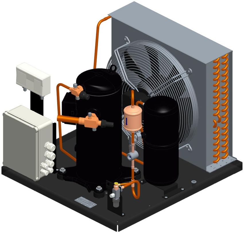
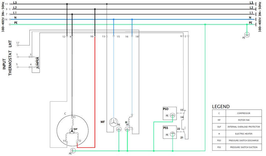
The Unit is fitted with a compressor, fan assembly, pressure switch, crankcase heater, in electrical box (see wiring
diagrams).
Ensure the electrical supply is disconnected before carrying out any wiring or repair of the Unit. All
cabling on site must conform with EN60204.
Warning: To ensure the quality of Unit it is essential to:
• Check that the installation power supply voltage is compatible with the voltage supply of the Unit (refer to
identification label).
• Check the compatibility of the wiring diagram with the installation (refer to wiring diagrams)
• Size the cables (power and control) according to the specifications of the Unit installed
• Ensure the power supply to the Unit is correctly protected and earthed
• Ensure the Unit is earthed when replacing components
• For Units with a 3-phase compressors, correct phase sequence for rotation direction must be observed. Determine
the phase sequence by using a phase meter in order to establish the phase orders of line phases L1,L2,L3. Connect
line phases, L1, L2, L3 to main switch terminals according wiring diagram. If the compressor scroll is rotating in the
wrong direction, please inverse 2 phases.
3.8 Connecting replacement components
Please refer to the wiring diagram supplied with the Unit when connecting components. For details follow
manufacturers’ datasheet of components you are replacing.
44. START UP
4.1 Leak detection
Never pressurize the circuit with oxygen or dry air. This could cause fire or explosion.
Perform a first leak detection in over pressure with nitrogen gas maximum test pressure is 28 bar.
All connections must be systematically checked for any leakage with an electronic leak detector for the type of
refrigerant used around the joints.
When a leak is discovered, repair the leak and repeat the leak detection.
4.2 Vacuum dehydration
Never use the Unit to vacuum the system.
Never use ohmmeter nor apply power to the compressor while it is under vacuum. It may cause internal damage.
Pull a deep vacuum of the installation to about 0.14mbar absolute.
Use the suitable vacuum pump (double stage is recommended).
Vacuum the system simultaneously from both LP and HP pressure sides.
4.3 Refrigerant charge
Never start the Unit under vacuum.
Charge the installation using only refrigerant for which the Unit has been designed for.
Charging with refrigerant should always take place in the liquid phase in order to maintain the correct blend of
zeotropic refrigerant.
Ensure liquid charge by checking the sight glass.
Charge the system to 4-5 bar when using R404A or equivalent and approximately 2 bars for R134a or equivalent.
The remaining refrigerant can be slowly charged into the suction line when the compressor is running, until the
nominal operating conditions of the installation are reached.
INSTALLATION INSTRUCTIONS
Complete the “pre-start check list” before switching on the installation.
Pre-start check list
1. The power supply is compatible with power supply indicated on the Unit label.
2. If oil sight glass is present, observe the oil level at the start.
3. Electrical safety devices are set correctly.
4. Electrical connections are properly fastened.
5. Service valves are fully open.
6. The crankcase heater is working (for Unit with scroll compressor must be energized minimum 12 hours before the
Unit starts).
7. Fan blades rotate freely and in proper rotation direction (sucking air from condenser towards compressor).
8. Safety pressure switches are set properly for LP and HP according to the refrigerant used and application envelop.
9. If available, the fan speed controller has been set properly. Supplied Units have fan speed set according the
manufacturer´s set up point.
10. The installation is given a final check for any possible faults.
Check list after start-up
After the installation has been running for several hours, carry out the following checks:
1. The power supply voltage and current consumption by the Unit is correct.
2. If oil sight glass is present, observe the oil level during operating condition to confirm the oil remains visible.
3. The high and low operating pressures are correct.
4. Fan blades are rotating freely.
5. Check if the airflow is from the condenser towards the fan.
6. Superheat and subcooling are on line with the state of the art (do not overcharge the system).
7. The system is checked again for leak.
8. For proper operation it is recommended to change the filter drier after 1st run of the Unit.
Make sure the installation is running smoothly.
The scroll compressor needs a run-in period minimum 72 hours to give its full performances. During this break-in the
power input can be slightly higher than normal conditions.
Carry out a general inspection of the installation (e.g. cleanliness, vibration and/or unusual noises).
Ensure the settings and the functions of the electrical circuits are correct.
55. SERVICING AND MAINTENANCE
No unauthorized modifications to the Units are allowed. Authorization from EMBRACO must be obtained prior to any
modification whatsoever. Do not use product containing alcohol or ethanol. Any faulty part must be replaced with the
original spare part. In case a replacement of electrical components of compressor is required, use a full KIT from
EMBRACO. In order to maintain the low noise of the Unit over time, we recommend replacing the anti-vibrations
mounts as soon as any change on the noise or vibration level of the Unit is noticed.
Always switch off the Units at main switch before opening the Units.
5.1 Fan
Use correct spare part KIT from EMBRACO.
5.2 Condenser
The condenser must be cleaned ideally twice a year (before and after the hot season).
5.3 Leak checking and periodical inspections
A leak check must be carried out at least once a year. It can vary according to the teqCO2, refrigerant and charge
used. Please refer to your local regulation. Check regularly:
• The condition of refrigeration connections (e.g. for any loosening or oxidation).
• Operating conditions.
• The mounting of the Unit on its base.
• The housing fixing (no vibration).
• Oil level for Scroll compressors.
5.4 Electrical checks
Systematically check all electrical components. If screwed terminal, tighten connections once a year.
Check regularly:
• Safety and control devices
• Crankcase heater operation.
5.5 Filter drier
Units are fitted with a brazed filter drier. When changing the filter drier, ensure that it is replaced with an equivalent
in capacity and pressure drop and with the correct direction of flow. For proper operation it is recommended to
change the filter drier after each service activity affecting refrigeration circuit.
6. WARRANTY
For information concerning the Unit warranty, please refer to our sales terms and conditions.
67. DECLARATION OF CONFORMITY
Supplied Units are in conformity with the following Directive (s):
• 2014/35/EU Low Voltage Directive (LVD)
• 2006/42/EC Machinery Directive
• 2011/65/EU RoHs Directive
• 2014/68/EU Pressure Equipment Directive (PED)
• 2009/125/EC Eco-design Regulation
Following Standards were applied:
• IEC60335-1 Safety of household and similar electrical appliances – General
• IEC60335-2-34 Safety of household and similar electrical appliances – Particular requirements for
motor-compressors
• IEC60204-1 Safety of machinery - Electrical equipment of machines - Part 1: General requirements.
• EN50581 Technical documentation for the assessment of electrical and electronic equipment with respect to the
restriction of hazardous substances.
• EN 13771-2:2017 Compressor and Units for refrigeration – Part 2: Units.
Specific IEC standard dependant of final appliances has to be tested on the complete appliance using EMBRACO
Units.
Certificates of conformity are available on request.
7Instruction d’installation
Lisez les instructions suivantes
soigneusement avant d'installer l'unité
Introduction:
Merci d'avoir choisi une unité EMBRACO. Cette unité a été conçue spécifiquement pour la réfrigération et
avec une installation conviviale dans l'esprit de gagner du temps sur site: Accès facile aux composants
pour faciliter la mise en service, le démarrage et la maintenance.
Cette notice d'instructions techniques comprend des informations détaillées concernant l'installation, la
mise en service, l'entretien et la maintenance.
1. AVERTISSEMENT ET PRÉCAUTIONS
1.1 Général
Avant d’installer les groupes, lisez attentivement toutes les instructions suivantes. Le non-respect de ces
avertissements de sécurité peut entraîner des blessures graves ou la mort.
• Lors de la conception de l'installation et de l'intégration de l'unité, l’installateur doit suivre toutes les
réglementations en vigueur en matière de sécurité électrique, de pression et d'inflammabilité.
• Les connexions électriques et le câblage des équipements doivent être conçus en tenant compte des
caractéristiques électriques du groupe et de ses composants électriques (pour plus de détails, veuillez contacter
l'assistance technique d'Embraco).
• Utilisez le groupe uniquement avec le réfrigérant indiqué sur l'étiquette du groupe.
• Utilisez le groupe uniquement avec l'alimentation électrique indiquée sur l'étiquette du groupe.
• L'incorporation du groupe dans l'installation ou tout service effectué doit être effectuée uniquement par du
personnel qualifié.
• La manipulation du groupe doit être effectuée avec soin en gardant à l'esprit le poids pour éviter les blessures.
L'équipement de protection (lunettes de sécurité, gants, casques et chaussures de protection.) doit être porté
pendant la manipulation de l'unité au moment de l'intégration d'origine et pendant l'entretien.
• Ne mettez pas le groupe sous tension avant de vous connecter à l'application.
• Évitez que le groupe ne démarre sous vide ou sans charge de réfrigérant.
• Utilisez l'appareil uniquement avec des composants électriques spécifiés par Embraco
• Pour le raccordement électrique, reportez-vous au schéma de câblage du groupe.
• Utilisez l'appareil uniquement dans un système mis à la terre.
• Un refroidissement correct de l'unité conformément aux spécifications doit être assuré.
• Pour une intervention de maintenance, suivez les instructions du fabricant de l'application.
• Coupez l'alimentation électrique avant de réparer le groupe
• Déchargez tous les condensateurs avant de réparer le groupe
• Retirez la pression du côté haute et basse pression avant de démonter l'unité.
• Utilisez un coupe-tube pour ouvrir le circuit de réfrigération. N'utilisez pas de chalumeau.
• Pour le remplacement du groupe, suivez les instructions d’ Embraco. Utilisez uniquement avec les composants
électriques spécifiés par Embraco.
• Avant de mettre le système sous tension, vérifiez la mise à la terre de l'unité et assurez-vous que les composants
électriques et la carosserie sont correctement fixés.
• Connectez l'équipement uniquement à une alimentation avec une connexion à la terre appropriée, une protection
contre les surintensités et des dispositifs de sécurité électrique.
• N'utilisez plus le compresseur démonté.
• Ne mélangez pas cette huile avec d'autres huiles et traitez-la correctement en raison de son risque d'inflammabilité.
• Avant de mettre les unités sous tension, assurez-vous que la protection du ventilateur est correctement installée.
1.2 Transport et manutention
• Ne transportez pas, ne stockez pas et ne manipulez pas le groupe à l'envers car l'unité contient un compresseur
avec de l'huile.
1.3 Installation
• Cette unité et tous les équipements doivent être installés par du personnel qualifié.
• L'installation doit être effectuée conformément aux normes de réfrigération et électriques applicables en vigueur
dans ce pays. Les meilleures pratiques de réfrigération doivent être suivies.
• EMBRACO ne sera en aucun cas responsable si l'installation et la maintenance ne sont pas effectuées
conformément aux instructions données dans ce manuel.
81.4 Cautions Précautions
• Les unités de l'application doivent être utilisées dans une plage de travail spécifiée par Embraco.
• Le réfrigérant entrant dans la conduite d'aspiration doit être en phase vapeur.
• Accordez une attention particulière au brasage correct ou à d'autres formes de raccordement dans le système pour
éviter la possibilité de fuites.
• Utilisez un détecteur de fuite adapté au fluide frigorigène respectif pour garantir l'efficacité maximale dans le
contrôle des fuites.
• Évitez d'endommager l'étiquette de l'unité pendant le processus d'assemblage.
• Les bonnes pratiques de réfrigération suggèrent un tirage au vide du système à la fois du côté basse et du haute
pression atteignant un niveau minimum de 0,14 mbar.
• Utilisez l'appareil uniquement avec des composants électriques spécifiés par le fabricant. Le boîtier électrique du
compresseur doit être situé dans une position où une distance de sécurité par rapport à tout plastique, mousse, fil ou
tout autre matériau inflammable est garantie. Le boîtier électrique ne doit pas être placé à proximité d'un bac à eau,
à proximité de l'isolation des tubes d'aspiration ou à proximité des connexions électriques ou du câblage de
l'application.
Lisez attentivement les instructions suivantes avant l'assemblage et la mise en service de cet appareil.
2. DONNÉES TECHNIQUES
2.1 Etiquette d'identification. Voir sur l'image 5. Vérifiez toujours si l'étiquette correspond au modèle requis à
installer.
2.2 Dispositifs de sécurité Toutes les unités sont fournies avec un BP réglable et un pressostat HP réglable ou
fixe. Préréglage en usine:
LP (MPa) /
Réfrigerants HP (MPa / PSIG)
Différentiel (MPa)
R404A, R449A, R452A, R448A 2.8 / 400 0.2 / 0.15
R134a, R513A 1.7 / 250 0.2 / 0.15
3. INSTALLATION
3.1 Déballage
Avant de déballer le groupe, vérifiez que l'emballage n'a pas été endommagé de quelque façon que ce soit et que
l'extérieur est en bon état.
3.2 Manipulation
L'unité emballée peut être levée par chariot élévateur ou transpalette. L'unité doit donc être conservée dans son
emballage jusqu'à ce qu'elle soit déplacée sur le site d'installation. Une fois l'emballage retiré, l'unité peut être
déplacée
3.3 Emplacement
Assurez-vous que l'unité ne doit pas bloquer ou obstruer les voies de communication, les portes, les volets ou le
mouvement du personnel.
La surface supportant l'unité doit être de niveau et capable de supporter le poids combiné de l'unité et du support.
Assurez-vous qu'il y a une distance suffisante entre l'unité et l'objet dans la zone environnante pour assurer une
bonne circulation de l'air.
L'unité doit être installée dans un endroit bien ventilé mais pas dans des endroits venteux. Assurez-vous qu'il y a une
bonne circulation d'air vers le condenseur. Il ne doit y avoir aucun obstacle à l'avant ou sur le côté de l'unité qui
pourrait provoquer une recirculation d'air vers le condenseur entraînant une température de condensation
anormalement élevée.
L'unité doit être montée avec un niveau élévé de compétence en réfrigération.
Assurez-vous que l'unité est tenue à l'écart des sources de chaleur, des zones humides, de l'atmosphère corrosive ou
de tout endroit présentant un risque d'explosion.
Ne dépassez pas la pression de service recommandée.
93.4 Niveaux sonores
Des précautions doivent être prises lors de l'installation pour ne pas générer de bruit et de vibrations
supplémentaires:
• L'unité doit être solidement montée sur une base stable et rigide.
• La tuyauterie de raccordement doit être suffisamment flexible pour éviter que les vibrations ne soient transmises au
reste de l'installation.
• Nous recommandons d'insérer un matériau isolant entre de l'unité et la base ou entre les supports de montage
mural et le mur. Il peut s'agir d'un coussin isolant ou de supports antivibrations (non fournis) conformes aux
recommandations du fabricant pour leur sélection et leur installation.
• La sélection des produits antivibrations et leur potentiel d'absorption des vibrations n'est pas de la responsabilité
d'Embraco.
• Le niveau de bruit final de l'installation dépend des propriétés de réflexion / absorption de l'environnement. Gardez
à l'esprit la règle générale selon laquelle l'installation de l'unité dans le coin des surfaces augmentera le niveau de
pression acoustique (en fonction du nombre de réflexions).
3.5 Montage
Assurez-vous que le groupe est solidement fixée au sol ou à la surface murale sur laquelle elle est montée à l'aide de
la fixation appropriée (non fournie).
3.6 Connexions frigorifiques
Pour assurer la qualité de nos produits, le circuit a été tire au vide et chargée d'azote gazeux
Avertissement: Pour maintenir la qualité de l'unité et garantir un fonctionnement correct, les précautions suivantes
doivent être prises:
• Vérifiez que la tuyauterie à raccorder est propre et sèche.
• Protégez le boîtier pendant le brasage des tuyaux.
• Purgez le système avec de l'azote pendant le brasage et assurez-vous que la flamme est éloignée des équipements
électriques.
• Isolez le tuyau d'aspiration jusqu'à la valve externe pour limiter la surchauffe.
• Utilisez uniquement le réfrigérant désigné pour lequel l'unité est approuvée (voir l'étiquette d'identification)
• N'ajoutez aucun additif ni colorant.
• Assurez-vous que la tuyauterie est bien supportée et aussi courte que possible pour éviter le piégeage d'huile et
pour améliorer l'absorption des vibrations et des pulsations.
• Dans les installations avec colonnes montantes verticales, il est nécessaire de créer un piège en U et un piège en P
et de vérifier la vitesse à l'intérieur du tuyau pour assurer une bonne circulation d'huile.
• Coupez et façonnez soigneusement la tuyauterie pour empêcher la poussière et les particules métalliques de
pénétrer dans le système. N'utilisez jamais de scie. Utilisez l'outil de pliage de taille appropriée pour le diamètre du
tuyau pour éviter que le tuyau ne soit comprimé.
• Collez les tuyaux avec du vinyle autocollant et fixez-les au mur avec des clips.
3.7 Connexions électriques
L'unité est équipée d'un compresseur, d'un ventilateur, d'un pressostat, d'une résistancede carter connecté dans des
boîtiers électriques (voir les schémas de câblage).
Assurez-vous que l'alimentation électrique est déconnectée avant d'effectuer tout câblage ou
réparation de l'unité. Tout le câblage sur site doit être conforme à EN60204.
Avertissement: Pour assurer la qualité de l'unité, il est essentiel de:
• Vérifiez que la tension d'alimentation de l'installation est compatible avec l'alimentation en tension de l'unité
(reportez-vous à l'étiquette d'identification).
• Vérifier la compatibilité du schéma de câblage avec l'installation (se référer aux schémas de câblage)
• Dimensionnez les câbles (alimentation et contrôle) selon les spécifications de l'unité installée
• Assurez-vous que l'alimentation électrique de l'unité est correctement protégée et mise à la terre
• Assurez-vous que l'unité est mise à la terre lors du remplacement des composants
• Pour les unités avec un compresseur triphasé, une séquence de phases correcte pour le sens de rotation doit être
observée. Déterminez la séquence de phases à l'aide d'un compteur de phase afin d'établir les ordres de phase des
phases de ligne L1, L2, L3. Connectez les phases de ligne, L1, L2, L3 aux bornes de l'interrupteur principal
conformément au schéma de câblage. Si le compresseur scroll tourne dans le mauvais sens de rotation, veuillez
inverser 2 phases.
3.8 Connexion des composants de remplacement
vous référer au schéma de câblage fourni avec l'unité lors de la connexion des composants. Pour plus de détails,
suivez la fiche technique du fabricant des composants que vous remplacez
104. DEMARRAGE
4.1 Détection des fuites
Ne jamais mettre le circuit sous pression avec de l'oxygène ou de l'air sec. Cela pourrait provoquer un incendie ou
une explosion.
Effectuer une première détection de fuite en surpression avec une pression d'essai maximale d'azote gazeux de 28
bars.
Toutes les connexions doivent être systématiquement vérifiées pour toute fuite avec un détecteur de fuite
électronique pour le type de réfrigérant utilisé autour des joints et brasures.
Lorsqu'une fuite est découverte, réparez la fuite et répétez la détection de fuite.
4.2 Tirage au Vide
N'utilisez jamais le groupe pour tirer au vide le circuit.
N'utilisez jamais un ohmmètre et ne mettez pas le compresseur sous tension lorsqu'il est sous vide. Cela peut
provoquer des dommages internes.
Tirez au vide profond l'installation à environ 0,14 mbar absolu.
Utilisez une pompe à vide appropriée (une pompe double étage est recommandé).
Effectuez le tirage au vide simultanément sur les 2 côtés pression BP et HP.
4.3 Charge de Réfrigerant
Ne démarrez jamais l'appareil sous vide.
Chargez l'installation en utilisant uniquement le réfrigérant pour lequel l'unité a été conçue.
La charge de réfrigérant doit toujours avoir lieu en phase liquide afin de maintenir le mélange correct de réfrigérant
zéotropique.
Assurez la charge liquide en vérifiant le voyant.
Chargez le système à 4-5 bar lorsque vous utilisez R404A ou équivalent et environ 2 bars pour R134a ou équivalent.
Le réfrigérant restant peut être lentement chargé dans la conduite d'aspiration lorsque le compresseur est en
marche, jusqu'à ce que les conditions de fonctionnement nominales de l'installation soient atteintes.
INSTRUCTIONS D'INSTALLATION
Suivre la «liste de contrôle avant démarrage» avant de mettre l'installation en marche.
Liste de contrôle avant démarrage
1. L'alimentation est compatible avec l'alimentation indiquée sur l'étiquette de l'unité.
2. Si un voyant d'huile est présent, observez le niveau d'huile au début.
3. Les dispositifs de sécurité électrique sont correctement réglés.
4. Les connexions électriques sont correctement fixées.
5. Les vannes de service sont complètement ouvertes.
6. La résistance de carter fonctionne (pour les unités avec compresseur à scroll, il doit être mis sous tension au
moins 12 heures avant le démarrage de l'unité).
7. Les pales du ventilateur tournent librement et dans le bon sens de rotation (aspirant l'air du condenseur vers le
compresseur).
8. Les pressostats de sécurité sont réglés correctement pour LP et HP en fonction du réfrigérant utilisé et de
l'enveloppe d'application.
9. Si disponible, le variateur de vitesse du ventilateur a été correctement réglé. Les unités fournies ont réglé la
vitesse du ventilateur en fonction du point de configuration du fabricant.
10. L'installation est soumise à un contrôle final pour tout défaut éventuel.
Liste de contrôle après le démarrage
Après plusieurs heures d'installation, procédez aux vérifications suivantes:
1. La tension d'alimentation et la consommation de courant de l'unité sont correctes.
2. Si un voyant d'huile est présent, observez le niveau d'huile pendant les conditions de fonctionnement pour
confirmer que l'huile reste visible.
3. Les pressions de fonctionnement haute et basse sont correctes.
4. Les pales du ventilateur tournent librement.
5. Vérifiez si le flux d'air est du condenseur vers le ventilateur.
6. La surchauffe et le sous-refroidissement sont conformes à l'état de la technique (ne surchargez pas le système).
7. Le système est à nouveau vérifié pour détecter les fuites.
8. Pour un fonctionnement correct, il est recommandé de changer le filtre déshydrateur après la première utilisation
de l'unité.
11Assurez-vous que l'installation se déroule correctement.
Le compresseur scroll a besoin d'une période de rodage d'au moins 72 heures pour donner ses pleines performances.
Pendant ce rodage, la puissance absorbée peut être légèrement supérieure aux conditions normales.
Effectuer une inspection générale de l'installation (par ex. Propreté, vibrations et / ou bruits inhabituels).
Assurez-vous que les réglages et les fonctions des circuits électriques sont corrects.
5. ENTRETIEN ET MAINTENANCE
Aucune modification non autorisée des groupes n'est autorisée. L'autorisation d'EMBRACO doit être obtenue avant
toute modification quelle qu'elle soit. N'utilisez pas de produit contenant de l'alcool ou de l'éthanol. Toute pièce
défectueuse doit être remplacée par la pièce de rechange d'origine. Dans le cas où un remplacement des composants
électriques du compresseur est nécessaire, utilisez un KIT complet d'EMBRACO. Afin de maintenir le faible bruit de
l'unité au fil du temps, nous recommandons de remplacer les supports anti-vibrations dès que tout changement sur
le niveau de bruit ou de vibration de l'unité est remarqué.
Éteignez toujours les unités au niveau de l'interrupteur principal avant d'ouvrir les unités.
5.1 Ventilateur
Utilisez le KIT de pièces de rechange correct de EMBRACO
5.2 Condenseur
Le condenseur doit être nettoyé idéalement deux fois par an (avant et après la saison chaude).
5.3 Vérification des fuites et inspections périodiques
Un contrôle d'étanchéité doit être effectué au moins une fois par an. Il peut varier en fonction du teqCO2, du fluide
frigorigène et de la charge utilisés. Veuillez vous référer à votre réglementation locale. Vérifiez régulièrement:
• L'état des connexions de réfrigération (par exemple pour tout desserrage ou oxydation).
• Des conditions de fonctionnement.
• Le montage de l'unité sur sa base.
• La fixation du boîtier (pas de vibration).
• Niveau d'huile pour compresseurs Scroll.
5.4 Contrôles électriques
Vérifiez systématiquement tous les composants électriques et resserrer les connexions une fois par an.
Vérifiez régulièrement:
• Dispositifs de sécurité et de contrôle
• Fonctionnement dz la résistance de carter.
5.5 Filtre Déshydrateur
Les groupes sont équipés d'un filtre déshydrateur à braser. Lors du remplacement du filtre déshydrateur, assurez-
vous qu'il est remplacé par une capacité et une perte de charge équivalente et dans le bon sens d'écoulement. Pour
un fonctionnement correct, il est recommandé de changer le filtre déshydrateur après chaque activité d'entretien
affectant le circuit de réfrigération.
6. GARANTIE
Pour plus d'informations sur la garantie de l'unité, veuillez consulter nos conditions générales de vente.
127. DÉCLARATION DE CONFORMITÉ
Les groupes fournis sont conformes aux directives suivantes:
• Directive basse tension 2014/35 / UE (LVD)
• Directive Machines 2006/42 / UE
• Directive RoHs 2011/65 / UE
• Directive 2014/68 / UE sur les équipements sous pression (DESP)
• Règlement d'éco-conception 2009/125 / CE
Les normes suivantes ont été appliquées:
• IEC60335-1 Sécurité des appareils électroménagers et similaires - Général
• IEC60335-2-34 Sécurité des appareils électroménagers et similaires - Exigences particulières pour
motocompresseurs
• IEC60204-1 Sécurité des machines - Équipement électrique des machines - Partie 1: Exigences générales.
• EN50581 Documentation technique pour l'évaluation des équipements électriques et électroniques en ce qui
concerne la restriction des substances dangereuses.
• EN 13771-2: 2017 Compresseur et unités de réfrigération - Partie 2: Unités.
La norme CEI spécifique dépendante des appareils finaux doit être testée sur l'appareil complet à l'aide des unités
EMBRACO.
Des certificats de conformité sont disponibles sur demande.
13Montageanleitung
Lesen Sie die folgenden Anweisungen vor der
Installation der Einheit aufmerksam
Einführung:
Vielen Dank für die Wahl eines EMBRACO Verflüssigungssatzes. Das Gerät wurde speziell für
Kälteanwendungen mit einem Auge auf eine servicefreundliche Montage vor Ort geplant: Die
Komponenten sind leicht zugänglich.
Diese technische Anleitung enthält detaillierte Informationen zu Installation, Inbetriebnahme, Start,
Bedienung und Wartung.
1. Warnung und Vorsichtsmaßnahmen
1.1 Generell
Vor Einbringen der Einheiten in die Anwendung lesen Sie alle folgenden Anweisungen sorgfältig durch. Die
Nichtbefolgung dieser Sicherheitshinweise könnte zu schweren Verletzungen oder zum Tod führen.
• Während der Konzeption der Anwendung und der Integration der Anlage muss der Originalgerätehersteller alle
gültigen und anwendbaren Regelungen hinsichtlich Elektrik, Druck und Entzündbarkeit befolgen
• Die elektrischen Anschlüsse und Verkabelungen müssen unter Berücksichtigung elektrischer Merkmale der Anlage
und ihrer elektrischen Komponenten gestaltet werden(für weitere Einzelheiten wenden Sie sich bitte an die
technische Unterstützung von Embraco).
• Verwenden sie die Anlage nur mit dem auf dem Typschild angegebenen Kältemittel.
• Verwenden sie die Anlage nur mit der auf dem Typschild angegebenen Stromversorgung.
• Die Einbindung der Anlage in die Endgeräte oder ähnliche Arbeiten müssen ausschliesslich von geschultem Personal
durchgeführt werden.
• Die Anlage muss mit Sorgfalt gehandhabt werden unter Beachtung des Gewichts, um eine Verletzung zu
vermeiden. Schutzausrüstung (Sicherheitsgläser, Handschuhe, Helme und Schutzschuhe) müssen während der
Einbringung der Anlage und während der Wartung getragen werden.
• Setzen Sie den Verflüssigungssatz nicht unter Strom vor Anschluss an die Gesamtanlage.
• Starten Sie die Anlage nicht unter Vakuum oder ohne Kältemittelfüllung.
• Die Einheit darf nur mit den vom Hersteller angegebenen elektrischen Komponenten verwendet werden.
• Für elektrische Anschlüsse nehmen Sie Bezug auf das Anschlußschema
• Verwenden Sie die Einheit nur in einem geerdeten Umfeld
• Eine ordnungsgemäße Abkühlung der Einheit gemäß Spezifikation ist sicherzustellen
• Für Service-Eingriffe folgen Sie den Anweisungen des Anlagenherstellers
• Schalten Sie die Stromversorgung ab vor Service-Eingriffen
• Entladen sie alle Kondensatoren vor Service-Eingriffen
• Lassen Sie den Druck aus Hoch- und Niederdruckseite ab, bevor sie die Einheit entfernen
• Verwenden sie Rohrschneider, um den Kältekreislauf zu öffnen. Verwenden sie keinen Brenner
• Für den Ersatz der Einheit folgen Sie den Anweisungen des Originalgeräteherstellers. Verwenden sie nur die vom
Hersteller angegebenen elektrischen Komponenten.
• Vor Energiezufuhr prüfen Sie die Erdung der Einheit und stellen sie sicher, dass die elektrischen Komponenten und
die Deckelung richtig befestigt wurden
• Die Ausrüstung ist nur zu verbinden mit einer Stromversorgung mit geeigneter Bodenverbindung (Erdung), mit
Überspannungsschutz und elektrischen Sicherheitsvorrichtungen
• Zerlegte Verdichter nicht wieder verwenden
• Mischen Sie dieses Öl nicht mit anderen Ölen und behandeln sie es ordnungsgemäß aufgrund des
Entzündungsrisiko
• Vor Energiezufuhr sicherstellen dass die Ventilatoren ordnungsgemäß eingebaut sind
1.2 Transport und Handhabung
• Das Gerät nicht auf dem Kopf stehend befördern, lagern oder handhaben, da es Verdichter mit öl enthält
1.3 Installation
• Dieser Verflüssigungssatz und alle damit verbundenen Geräte sind ausschließlich durch Fachpersonal zu installieren.
• Die Installation hat unter Beachtung der kälte- und elektrotechnischen Standards des jeweiligen Landes zu
erfolgen. Es müssen die optimalen kältetechnischen Verfahren angewendet werden.
• Unter keinen Umständen haftet EMBRACO für Installations- und Wartungsarbeiten, die nicht in Übereinstimmung
mit den Anleitungen dieses Handbuches durchgeführt wurden.
141.4 Vorsichtsmaßnahmen
• Die Einheiten müssen innerhalb eines vom Hersteller angegebenen Arbeitsbereichs verwendet werden.
• In die Saugleitung gelangendes Kältemittel muss in der Dampfphase sein.
• Besondere Aufmerksamkeit ist zu richten auf die korrektes Schweißen oder auf andere Formen von
Leitungsverbindungen im System, um eventuelle Lecks zu vermeiden.
• Verwenden Sie einen für das jeweilige Kältemittel geeigneten Detektor, um die höchstmögliche Effizienz bei der
Beherrschung der Leckage zu garantieren.
• Vermeiden Sie die Beschädigungen am Typschild während des Montageprozesses.
• Gute Praxis in der Kältetechnik empfiehlt die Evakuierung des Systems sowohl auf der Tief- als auch auf der
Hochdruckseite bei einem zu erreichenden Mindestwert von 0,14 mbar.
• Die Einheit darf nur mit vom Hersteller vorgegebenen elektrischen Komponenten verwendet werden. Der
elektrische Anschlusskasten des Verdichters sollte in einer Position angebracht werden, in der eine sicherer Abstand
von Kunststoff, Schaumstoff, Draht oder anderen entzündbaren Materialien gewährleistet ist. Der elektrische
Anschlusskasten darf nicht in der Nähe eines Wassertabehälters, nahe der Isolierung von Saugschläuchen oder in der
Nähe von elektrischen Anschlüssen oder von Anwendungsverdrahtungen angebracht werden.
Lesen sie sorgfältig die folgenden Anweisungen vor Montage und Inbetriebnahme dieses
Verflüssigungssatzes.
2. TECHNISCHE DATEN
2.1 Typenschild
Immer überprüfen, ob das Etikett dem entsprechenden Modell entspricht, das zu installieren ist.
2.2 Sicherheitseinrichtungen Sämtliche Geräte sind mit einstellbaren Nieder- und Hochdruckschaltern
ausgestattet. Werksseitige Voreinstellung:
LP (MPa) /
Kältemittel HP (MPa / PSIG)
Differential (MPa)
R404A, R449A, R452A, R448A 2.8 / 400 0.2 / 0.15
R134a, R513A 1.7 / 250 0.2 / 0.15
3. INSTALLATION
3.1 Auspacken
Vor dem Auspacken des Geräts sicherstellen, dass die Verpackung unbeschädigt und in einem guten Zustand ist.
3.2 Handhabung.
Der verpackte Verflüssigungssatz kann mit einem Gabelstapler oder Palettenhubwagen angehoben werden. Daher
sollte man das Gerät erst am Installationsort auspacken.
3.3 Location
Verflüssigungssätze mit Gehäuse dürfen Durchgänge, Türen, Fensterläden nicht blockieren oder versperren bzw. den
Personalverkehr nicht behindern.
Die Oberfläche, die den Verflüssigungssatz abstützt, muss eben sein und das kombinierte Gewicht von Gerät und
Halterung tragen können
Sicherstellen, dass zwischen Verflüssigungssatz und Gegenständen in seiner Nähe ausreichend Abstand für eine
angemessene Luftzirkulation vorhanden ist.
Verflüssigungssätze mit Gehäuse müssen in einem gut belüfteten aber windgeschütztem Bereich installiert werden.
Sicherstellen, dass der Verflüssiger an einem gut belüfteten Ort aufgestellt ist. Es sollten keine Hindernisse vor oder
seitlich am Gerät vorhanden sein, welche eine Luftrückführung zum Verflüssiger und somit eine ungewöhnlich hohe
Verflüssigungstemperatur verursachen könnten
Der Verflüssigungssatz mit Gehäuse ist waagrecht nach den besten kältetechnischen Verfahren zu montieren
Den Verflüssigungssatz fern von Wärmequellen, feuchten Stellen, Orten mit korrosiver Atmosphäre oder Stellen, an
denen Explosionsgefahr besteht, montieren
Sorgen Sie dafür, dass die Anlage den empfohlenen Betriebsdruck nicht überschreitet
153.4 Geräuschpegel
Bei der Montage sind entsprechende Vorkehrungen zu treffen, um zusätzliche Geräusche und Schwingungen zu
vermeiden:
• Die Geräte müssen fest auf einem stabilen und steifen Sockel installiert werden
• Leitungsverbindungen müssen ausreichend biegsam sein, um sicher zu stellen dass Vibrationen nicht an den Rest
der Anlage übertragen warden
• Es empfiehlt sich, Isoliermaterial zwischen den Gerätefüßen und dem Sockel oder zwischen den Wandhalterungen
und der Wand einzufügen. Dazu eine isolierende Unterlage oder schwingungsdämpfende Halterungen verwenden
(nicht im Lieferumfang), die gemäß Herstellerempfehlungen für die Montage geeignet sind
• EMBRACO ist nicht für die Auswahl von schwingungsdämpfenden Produkten und deren Wirkungsgrad
verantwortlich
• Der letztendliche Lärmpegel der Anlage hängt von Reflexions-/Absorptionseigenschaften der Umgebung ab.
Beachten sie im Allgemeinen, dass die Installation der Einheit in der Ecke den Schalldruckpegel erhöhen (abhängig
von der Anzahl der reflektionen)
3.5 Aufstellung
Stellen Sie sicher, dass das Gerät mit geeigneten Befestigungen am Untergrund bzw. an der Wand befestigt ist (nicht
im Lieferumfang).
3.6 Kältetechnische Anschlüsse
Für eine optimale Qualität unserer Produkte werden Verflüssigungssätze evakuiert und mit Stickstoff gefüllt.
Achtung: Für eine optimale Qualität und Funktionalität eines EMBRACO-Verflüssigungssatzes sind die folgenden
Vorkehrungen zu treffen:
• Kontrollieren Sie, dass die angeschlossenen Leitungen sauber und trocken sind.
• Schützen Sie das Gehäuse beim Verlöten der Leitungen.
• Spülen Sie das System mit Stickstoff beim Löten und sorgen Sie für ausreichend Abstand zwischen Flamme und
Elektroausrüstung.
• Isolieren Sie die Saugleitung bis zum Ventil am Verdichtereingang, um die Sauggasüberhitzung einzuschränken.
• Verwenden Sie nur das für den Verdichter vorgesehene Kältemittel (siehe Typenschild).
• Geben Sie keine Zusatz- oder Farbstoffe dazu.
• Stellen Sie sicher, dass die Leitungen gut abgestützt sind, und halten Sie den Abstand zwischen den Halterungen
möglichst klein, um Ölansammlungen zu verhindern und die Schwingungen optimal aufzunehmen.
Bei Anlagen mit Steigleitungen könnte es erforderlich sein,
Siphons einzubauen und den Leitungsdurchmesser zu reduzieren, damit eine ausreichende Ölumwälzgeschwindigkeit
gewährleistet ist.
• Schneiden und formen Sie die Leitungen so, dass keine Staub- oder Metallteilchen in die Anlage geraten.
Verwenden Sie keine Säge. Verwenden Sie ein Biegewerkzeug mit der korrekten Größe für den Leitungsdurchmesser,
um die Leitung nicht zusammenzudrücken.
• Verkleben Sie die Leitungen mit Vinylklebeband und befestigen Sie sie mit Klemmen an der Wand.
3.7 Elektrische Anschlüsse
Das Gerät ist ausgestattet mit einem Verdichter, einem vollständigen Lüfter, Druckschalter, Kurbelwannenheizung
verbunden über eine an einer DIN-Leiste montierten Klemmleiste.
Stellen Sie vor Arbeiten an der Verkabelung oder Reparaturarbeiten sicher, dass die Stromversorgung
getrennt wurde. Alle vor Ort montierten Kabel müssen der Norm EN 60204 entsprechen.
ACHTUNG: Für eine optimale Qualität eines EMBRACO-Verflüssigungssatzes ist folgendes erforderlich:
• Kontrollieren,ob die Versorgungsspannung am Installationsort mit dem Verflüssigungssatz kompatibel ist (siehe
Typenschild).
• Die Übereinstimmung von Schaltplan und Anlage prüfen (siehe Schaltplan)
• Die Kabel (Leistungs- und Steuerkreise) müssen den Spezifikationen des installierten Verflüssigungssatzes
entsprechen.
• Sicherstellen, dass die Stromversorgung zur Einheit richtig abgeschirmt und geerdet ist.
• Beim Austausch von Komponenten sicherstellen, dass das Gerät geerdet ist.
• Bei Einheiten mit 3-phasigem Verdichter muss eine korrekte phasensequenz für die Drehrichtung des Verdichters
eingehalten werden.
- Die Phasensequenz mit einem Phasenmessgerät prüfen, um die Phasenfolge der Linienphase L1, L2, L3 zu ermitteln
- Phasen L1, L2, L3 mit den entsprechenden Terminals des Hauptschalters verbinden gemäß Schaltplan
Wenn der Scroll-Verdichter in die falsche Richtung dreht, dann bitte 2 Phasen umkehren
163.8 Verbindung von Ersatzteilen
Beachten Sie den mit dem Verflüssigungssatz mitgelieferten Schaltplan beim Anschluss von Kompontenten. Für
Details folgen Sie den Angaben der Hersteller von Komponenten, die sie ersetzen.
4. INBETRIEBNAHME
4.1 Dichtheitsermittlung
Niemals den Kältekreislauf mit Sauerstoff oder trockener Luft unter Druck setzen. Das könnte Feuer - oder eine
Explosion verursachen.
Eine erster Dichtheitsnachweis in Überdruck mit stickstoffgas durchführen. Maximaler Prüfdruck ist 28 Bar.
Alle Verbindungen müssen systematisch auf jegliche Leckage überprüft werden unter Verwendung eines
elektronischen Lecksuchgeräts, welches für das jeweilige Kältemittel geeignet ist
Wird ein Leck entdeckt, repariert man das Leck und wiederholt die Dichtheitsermittlung.
4.2 Wasserentzug unter Vakuum
Benutzen sie niemals den Verdichter um das System zu vakuuieren.
Verwenden sie niemals ein Ohmmeter und setzen Sie den Verdichter niemals unter Strom während er unter Vakuum
steht. Dies kann innere Schäden verursachen.
Ziehen Sie ein tiefes Vakuum der Anlage auf rund 500 µ m Hg (0,67mbar) absolut.
Verwenden Sie eine geeignete Vakuumpumpe (doppelstufig empfohlen).
Vakuumieren Sie gleichzeitig von der Nieder- und der Hochdruckseite
4.3 Kältemittelfüllung.
Den Verdichter niemals unter Vakuum starten.
Die Anlage nur mit dem Kältemittel befüllen, welches für das Gerät vorgesehen ist (siehe Typenschild).
Das einzufüllende Kältemittel sollte stets im flüssigen Zustand sein, um die korrekte zeotrope Kältemittelmischung zu
erhalten.
Bei Verwendung von R-404A empfiehlt es sich, die Anlage auf 4 oder 5 bar zu beaufschlagen, während bei R-134a 2
bar benötigt werden.
Das restliche Kältemittel kann bei laufendem Verdichter langsam der Saugleitung zugeführt werden, bis die Anlage
die Nennbetriebsbedingungen erreicht.
MONTAGEANLEITUNG
Befolgen Sie die komplette „Checkliste vor dem Start“ vor Einschalten der Anlage
Checkliste vor dem Start
1. Die Versorgungsspannung ist mit der Spannung des Verflüssigungssatzes kompatibel
2. Wenn ein Ölschauglas vorhanden ist dann den Ölstandspegel zu Beginn beobachten
3. Die elektrischen Sicherheitseinrichtungen des Verflüssigungssatzes sind korrekt eingestellt
4. Elektrische Verbindungen sind richtig befestigt
5. Die Serviceventile sind ganz geöffnet
6. Die Kurbelwannenheizung funktioniert (muss mindestens 12 Stunden vor Start des Verdichters eingeschaltet
werden)
7. Die Ventilatoren des Verflüssigungssatzes drehen frei
8. Der Sicherheitsdruckschalter ist für Nieder- und Hochdruck entsprechend dem verwendeten Kältemittel und des
jeweiligen Anwendungsfensters richtig eingesetzt
9. Der Drehzahlregler des Lüfters wurde richtig eingestellt.
10. Die Anlage wurde einer letzten Fehlerprüfung unterzogen
Checkliste nach dem Anlauf
Nachdem die Anlage mehrere Stunden gelaufen ist führen Sie die nachfolgenden Kontrollen durch. Stellen Sie
folgendes sicher:
1. Korrekte Strom- und Spannungsaufnahme des Verflüssigungssatzes
2. Bei vorhandenem Ölschauglas das Ölstandsniveau beobachten während des Betriebs, um zu bestätigen, dass das
Öl weiterhin sichtbar bleibt
3. Korrekter hoher und niedriger Betriebsdruck der Anlage
4. Freie Rotation der Ventilatoren
5. Überprüfen, ob der Luftstrom vom Verfüssiger zum Ventilator kommt
6. Überhitzung und Unterkühlung sind im Bereich der Vorgaben (System nicht überlastet)
7. Erneute Dichtheitsprüfung der Anlage
17You can also read