Fabrication of 15NV centers in diamond using a deterministic single ion implanter - Schmidt-Kaler
←
→
Page content transcription
If your browser does not render page correctly, please read the page content below
PAPER • OPEN ACCESS

Fabrication of 15NV− centers in diamond using a deterministic single ion
implanter
To cite this article: Karin Groot-Berning et al 2021 New J. Phys. 23 063067

View the article online for updates and enhancements.

                               This content was downloaded from IP address 134.93.30.9 on 23/06/2021 at 16:19
New J. Phys. 23 (2021) 063067                                                               https://doi.org/10.1088/1367-2630/ac0753

                                 PAPER

                                 Fabrication of 15 NV− centers in diamond using a deterministic
O P E N AC C E S S
                                 single ion implanter
R E C E IVE D
6 January 2021
                                 Karin Groot-Berning1 , ∗ , Georg Jacob2 , Christian Osterkamp3 , Fedor Jelezko3 and
R E VISE D
18 May 2021                      Ferdinand Schmidt-Kaler1 , 4
                                 1
AC C E PTE D FOR PUBL IC ATION       QUANTUM, Johannes Gutenberg-Universität Mainz, Staudinger Weg 7, 55128 Mainz, Germany
2 June 2021                      2
                                     Alpine Quantum Technologies GmbH, Technikerstrasse 17/1, 6020 Innsbruck, Austria
                                 3
PUBL ISHE D                          Institut für Quantenoptik, Universität Ulm, Albert Einstein Allee 11, 89081 Ulm, Germany
                                 4
23 June 2021                         Helmholtz-Institut Mainz, 55128 Mainz, Germany
                                 ∗
                                     Author to whom any correspondence should be addressed.

Original content from            E-mail: karin.groot-berning@uni-mainz.de
this work may be used
under the terms of the           Keywords: deterministic implantation, single ion implantation, NV creation
Creative Commons
Attribution 4.0 licence.
Any further distribution
of this work must                Abstract
maintain attribution to
the author(s) and the            Nitrogen vacancy (NV) centers in diamond are a platform for several important quantum
title of the work, journal       technologies, including sensing, communication and elementary quantum processors. In this letter
citation and DOI.
                                 we demonstrate the creation of NV centers by implantation using a deterministic single ion source.
                                 For this we sympathetically laser-cool single 15 N+
                                                                                   2 molecular ions in a Paul trap and extract them
                                 at an energy of 5.9 keV. Subsequently the ions are focused with a lateral resolution of 121(35) nm
                                 and are implanted into a diamond substrate without any spatial filtering by apertures or masks.
                                 After high-temperature annealing, we detect the NV centers in a confocal microscope and
                                 determine a conversion efficiency of about 0.6%. The 15 NV centers are characterized by optically
                                 detected magnetic resonance on the hyperfine transition and coherence time.

                                 1. Introduction

                                 1.1. Motivation
                                 In the past two decades research on single nitrogen vacancy (NV) centers in diamond has undergone a
                                 dramatic progress. Since the first observation of single NVs with a confocal microscope and the
                                 demonstration of optically detected magnetic resonance (ODMR) [1], there have been numerous
                                 experiments which show a multitude of applications covering many fields such as metrology and quantum
                                 information processing. Among these applications are quantum sensors for magnetic and electric fields on
                                 the nanometer length-scale as well as microwave sensors [2].
                                     A well established method to create NV centers is the implantation of nitrogen ions with subsequent
                                 annealing of the sample [3]. This approach is especially beneficial in cases where a precise placement of NVs
                                 is necessary. Typically, these are applications where the NVs are placed within dedicated structures in order
                                 to couple them to light fields e.g. inside a photonic waveguide structure [4, 5] or a solid immersion lens [6].
                                 In these applications, implantation allows for circumventing the necessity of manufacturing such structures
                                 around pre-existing NV centers. The requirements on the resolution thereby, is given by the wavelength of
                                 the optical fields and thus is in the order of less than 100 nm. To this date, various techniques have been
                                 proposed and developed to reach that aim. For example, nanofabricated masks or pierced AFM tip which
                                 provide apertures [7, 8]. Another approach is using a focused ion beam with the respective resolution. This
                                 circumvents the need for employing a mask or an AFM tip near the focal plane [5]. However, these
                                 techniques are using stochastic sources, limiting the applications to cases where single NV devices can be
                                 post selected depending on whether an ion was implanted or not. This rules out applications which rely on
                                 coupling NV centers via their mutual dipolar magnetic interaction which is on the scale of a few tens of
                                 nanometers. Such a coupling between two NVs has been demonstrated in various experiments [9–11].
                                 Scalable use of this resource e.g. for creation of entanglement in the context quantum information

                                 © 2021 The Author(s). Published by IOP Publishing Ltd on behalf of the Institute of Physics and Deutsche Physikalische Gesellschaft
New J. Phys. 23 (2021) 063067 K Groot-Berning et al
processing calls for deterministic placement of single NVs with nanometer resolution. The need for arrays
of single NVs at nanometer accuracy is even more important in view of building a scaled-up quantum
processor or simulator based on this solid state platform [12–14].
To this goal we implement an intrinsically deterministic ion source by repetitively loading a single
laser-cooled nitrogen molecular ion into a linear Paul trap and launch it from there. The laser cooling
provides a small phase space occupation of the generated beam in both, the transversal and longitudinal
direction. The former allows for tight focusing without need for spacial filtering which would destroy the
deterministic property of the source. The latter results in a low energy dispersion, important for avoiding
chromatic aberration when focusing by electric field lenses. Additionally, our method uses singly charged
ions at energies lower than 10 keV, unlike methods that rely on the detection of single ion impact events
[15]. The low energy implantation reduces position uncertainty due to straggling and surface destruction of
the bulk diamond. Likewise the very same apparatus allows for transmission imaging of the substrate using
single extracted calcium ions [16]. This provides a precise referencing and positioning of the dopants with
respect to transmissive markers, free of parallax errors. Minimal charging and irradiation of the diamond
substrate is ensured by using single ions for imaging. In this paper we present a proof of principle
experiment which demonstrates the creation of NV centers with high resolution by focusing a nitrogen
beam generated by this source. Although the deterministic production of single NV centers with this
method is currently severely limited by the creation yield, additional measures—such as co-implantation of
sulfur [17], surface termination [18], diamond overgrowth [19] and electron irradiation [20]—could
realize such a truly deterministic creation process in the future. Also, the apparatus can be used as a
deterministic source of any atomic and molecular ions and we envision for the future co-implanting of
other ion species, e.g. 13 C+ ions, to tailor the spin-environment of the NV center.
2. Experimental apparatus and procedures
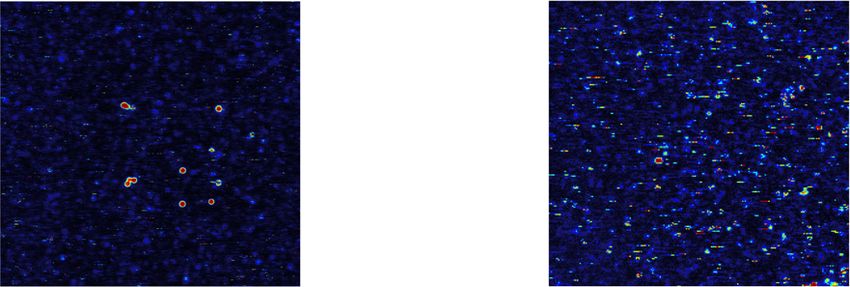
A linear Paul trap acts as an ultracold ion source [21–24]. The trap consists of four gold coated alumina
chips mounted in an X-shaped arrangement, see reference [21] and figure 1 for details. One pair of
diagonally opposing chips are supplied with RF voltage giving rise to a radial confinement of the ions. The
chips of the other pair is segmented into 11 electrodes. These segments allow for shaping the axial potential
by applying DC voltages. Along the axial direction, the trap is encapsulated by two pierced end-caps with a
length of 10 mm, allowing for the extraction of the ions by switching them to high voltage.
Calcium atoms are provided by an oven which is directed towards the center of the trap. Inside the
trapping volume the atoms are photo-ionized, trapped and laser cooled with light at 397 nm on the S1/2 to
P1/2 dipole transition. Trapped ions are detected and automatically counted by imaging their fluorescence
onto an EMCCD-camera5 . The loading of a predefined number of calcium ions is accomplished by an
automated procedure: first, a random number of ions is trapped, cooled and counted from the camera
image. If necessary, ions are removed by lowering the axial trapping potential with a predefined voltage
sequence. Subsequently, the success of this sequence is evaluated by counting the number of ions again and
in case of discrepancy, the procedure is repeated.
Ion species other than calcium are loaded by means of a commercial ion gun6 from gaseous sources as
well as solid sources. The remainder of this paper is solely concerned with making use of the gaseous source.
If the reader is interested in single-ions-on-demand from solid sources we refer to examples for
praseodymium and thorium [21, 25]. We control the flux from the isotopically pure 15 N2 gas source7 into
the ion gun volume with a needle valve. Here, the molecules are ionized by electron impact. Subsequently
the ions are extracted with typically 500 eV and are collimated to a beam which is guided and focused onto
the hole of one of the trap endcaps. Deflection electrodes allow for blanking of this beam i.e. switching the
loading of the trap on and off. For the gaseous source it is sufficient to direct the ion beam into the trap for
a fixed period of time. Within an average loading time of about 30 s we are trapping one 15 N2 ion. We
conjecture a loading mechanism facilitated by the modulation of the axial trapping potential due to the RF
drive. This allows ions to enter the trap at the lower turning point of the axial potential modulation and
keep them confined sufficiently long for sympathetic cooling such that their energy is reduced below the
trap depth.
Note, that N+ 2 ions from the gas source enter the trap at random times which makes a successful capture
more difficult, as compared to the case of laser-ablated targets where ions enter with a fixed time delay such
that a time-dependent voltage sequence at the endcap electrodes can be employed to decelerate and capture
5 Andor iXon X3, DU-860E-CS0-UVB, Andor Technology, Belfast, Northern Ireland.
6 Ion Source IQE 12/38, SPECS Surface Nano Analysis GmbH, 13355 Berlin, Germany.
7 Gas source 15 N2 , 364584-1L-EU, 98% 15N, Sigma-Aldrich.
2New J. Phys. 23 (2021) 063067 K Groot-Berning et al
Figure 1. Sketch of the experimental setup: the ion gun serves as a source for molecular 15 N+2 ions, which are loaded into the
linear Paul trap together with atomic Ca+ ions from an oven. A Wien filter after the ion gun (not shown) may be used. The ion
extraction from the Paul trap is achieved by applying a voltage pulse to a pierced endcap electrode. A pair of deflection electrodes
are used for beam steering, and the beam is focused with an Einzel-lens. A three-dimensional nano-translation stage with the
probe holder and an optional wedged blade can be used for ion beam characterization together with the ion detector.
them [21]. Another challenge is the much higher gas load from the ion source towards the trap chamber,
which we solve by differential pumping.
The nitrogen molecular ions are sympathetically cooled via their Coulomb interaction with the laser
cooled calcium ions. A voltage sequence, similar to the aforementioned sequence for the loading of a given
number of calcium ions, is applied in order to prepare a crystal consisting of exactly one calcium and one
nitrogen molecular ion. The existence of a trapped nitrogen ion is detected by a shift of the calcium ion
from its former equilibrium position on the camera image to the side, whereas the other ion does not emit
light, thus coined briefly ‘dark ion’.
The deterministic source is implemented by extracting the single ion(s) from the trap. The accelerating
electric field is provided by applying high voltages of up to −3 kV to one of the pierced endcaps. The ion
kinetic energy is doubled by switching the voltage to a positive value while the ion is inside the endcap hole.
Alignment and scanning of the ion beam is accomplished by two pairs of deflection electrodes which are
placed along the ion pathway. Depending on the charge to mass ratio, the dark ion is either faster or slower
than the calcium ion. This fact can be harnessed to separate the calcium. In case of a higher charge to mass
ratio compared to calcium, the dark ion e.g. 15 N2 will arrive earlier at the endcap. At the moment the dark
ion is inside the endcap, the voltage of the endcap is switched to a positive value, deflecting the calcium ion
back when approaching the endcap. In the case where the charge to mass ratio is lower, the dark ion will
leave the endcap later than the calcium ion. Switching the voltage of the endcap to a positive value is
performed when the calcium ion has already left the endcap, resulting in a lower energy compared to the
dark ion. Because of this, the deflection electrodes act differently on the two ion species, resulting in a
separation of the calcium ion.
For an unambiguous determination of the dark ion species, i.e. to identify the trapped particle as a
successfully loaded 15 N+2 molecular ion, we extract the ions and detect them after a flight of 428 mm in
length using a secondary electron multiplier (SEM). The SEM is located at the very end of the beam-path
and can be operated for ion detection if the target mount is moved out of the beam-path via a piezo
translation stage (see figure 1). The overall detection efficiency was measured to be 96%± 2%.
During ion extraction, we switch off the RF amplitude, to avoid shot-to-shot modifications of the ion
trajectory. These modifications originate from the time dependent electric fields of the RF drive at the
vicinity of the endcap in combination with a timing jitter of the exact onset of the extraction voltage. We
determine the mass of the extracted ions, from time-of-flight (TOF) measurements, discriminating between
15 + 15 14 +
N2 , N N , and 14 N+ 2 , see figure 2(a). The trigger for the HV switching and RF switching is chosen
such that the velocity modification is minimal, see figure 2(b). Prior to extraction, we arrange the order of
the ions in the linear crystal, such that the lighter nitrogen ion is ahead. This prevents a Coulomb
interaction of the nitrogen ion with the heavier and thus slower calcium ion. The ordering of ions is
achieved by briefly melting and then recrystallizing the crystal, followed by a check of the right ion order
from an EMCCD image of the fluorescence. In future, we may apply deterministic and fast swapping, as
demonstrated experimentally [26]. We focus the ion beam by an electrostatic lens, see [16] for details. To
optimize and finally characterize the spot size, we sweep a mechanical wedge into the focus and find
σ Ca = 11(2) nm, and σ N2 = 121(35) nm, respectively, see figures 2(c) and (d). For this experiment the same
3New J. Phys. 23 (2021) 063067 K Groot-Berning et al
Figure 2. Ion beam characterization: we employ the SEM detector and remove the diamond sample from the ion pathway. (a)
TOF signal in the SEM from single 15 N+ 15 14 + 14 +
2 , N N , and N2 , ions after a 0.428 m travel. After carefully purging all tube
connections between 15 N2 gas bottle and ion gun we found no indication for 14 N+ 2 ions. However, after a waiting time of 5 days,
the histogram shows a peak at mass 28, which was assigned to the isotope 14 N. (b) Velocity variations of 40 Ca (diamond) and
15
N2 (dots) ions as a function of delay between RF and DC switching. Ions with a mass of 40 and 30, respectively, arrive at
different times at the position of the endcap hole, and explore different phases of the RF drive field. (c) Focus spot determination
of Ca ions, measured by sweeping the wedge into the beam and observing the partial blocking, which is detected from the SEM
counts. For 40 Ca+ ions we obtain a σ = 11(2) nm in x-direction. The data acquisition time for the extraction of 380 ions was
approximately 17 min, which corresponds to a loading rate of 22.4 ions/min. (d) Focus spot determination of nitrogen molecular
ions yielding σ = 121(35) nm in x-direction. The measuring time for the extraction of 289 nitrogen ions takes about 117 min,
which results in a loading rate of 2.5 ions/min. We conjecture thermal and electrical drifts as well as mechanical vibrations as
major source of beam pointing fluctuations.
detector is used as for the TOF measurements. Note that the wedge positions for each shot was obtained
using the Bayes experimental design method [27]. This leads to an accumulation of the positions around
the turning points of the Gaussian error function, which was fitted to the data to obtain the sigma of the
beam focus. We conjecture that long term drifts are affecting the spot size of the N+ 2 , as the data acquisition
time for the Ca+ spot measurement is about 2 orders of magnitude faster. Sympathetic cooling of a dark
ion of mass u = 30 with 40 Ca+ is expected to work efficiently, since the masses are about equal in the mixed
crystal and thus the coupling of radial vibrational degrees of motion is still sufficient [28].
3. Sample preparation and implantation
Before any implantation was performed, the diamond host sample, a commercial type IIa electronic grade
diamond from supplier Element Six, was investigated with a home-built confocal microscope setup which is
described in section 4. Stable NV− centers were found in a concentration of 1 NV− per 100 μm2 (or 0.27
parts per trillion, ppt). After careful cleaning, we fix the sample on the three-axis nano-positioner in the
UHV setup, see figure 1. The diamond was exposed to accelerated focused nitrogen ions of isotope 15 N+ 2 .
Since each single nitrogen ion is trapped and identified prior to implantation, the dose can be controlled at
a single ion level. A pattern of 5 × 5 was implanted with a distance of 2 μm between the single implantation
spots by moving the sample with the nano-positioner. The dose κ can be adjusted freely and was varied
from one to 20 ions per spot, see figure 3 for details. According to SRIM simulations the used 3 keV
implantation energy per atomic ion corresponds to a penetration depth of 4.2 nm with an uncertainty of
±2.2 nm and therefore the resulting NV centers can be considered as shallow [29].
The implanted sample was acid cleaned in a mixture of sulfuric, nitric and perchloric acid (ratio 1:1:1)
which was heated to 130 ◦ C for 2 h, in order to remove any dirt from the surface. Especially any graphitic
layer which could be produced during the ion bombardment is removed by this treatment.
A successive annealing procedure under ultra-high vacuum was subsequently performed in order to
activate NV centers. During this process, vacancies (empty lattice sites) that are created due to collisions
during the implantation process, become mobile and pair with implanted nitrogen atoms forming stable
4New J. Phys. 23 (2021) 063067 K Groot-Berning et al
Figure 3. Implantation pattern with different ion quantities κ per spot which are separated by 2 μm. Region I (green) was
implanted with 15 N+ + 15 +
2 and Ca , whereas the regions A–E (purple) were implanted with N2 ions only. The different ion doses
for the different regions are selected to be I: κI = 20 ions
spot , A: κA = 20 ions
spot , B: κB = 10 ions ions ions
spot , C: κC = 4 spot , D: κD = 2 spot and E:
ion
κE = 1 spot .
nitrogen-vacancy centers [30]. The temperature was set to 250 ◦ C for 1 h to keep a high vacuum during the
annealing process. Then, the temperature was ramped up to 900 ◦ C and hold for another 2 h, with a
vacuum of 10−7 mbar. Finally, the system was cooled down. Another acid boiling step was included to
ensure the oxygen termination of the diamond surface, which is essential for the preservation of the NV−
charge state of shallow NVs [18, 31].
4. NV characterization
Confocal imaging was performed on a home-built confocal microscope consisting of a 518 nm diode laser,
a movable micrometer stage, an oil immersion objective (NA = 1.4) and an avalanche photo diode. A
lateral x–y-scan of the diamond sample can be seen in figure 4. Clearly visible are spots with high count rate
(bright spots) coming from the NV center fluorescence to which the setup is optimized by an optical
filtering system (excitation: 535/20BP, detection: 560LP). In total, six stable spots can be observed in region
I (figure 4(a)), showing the typical fluorescence spectrum of NV centers, see figure 5. Some of them are
present in the NV0 charge state with no accessible electron spin and therefore cannot be used for electron
spin resonance (ESR) measurements. The fluorescence spectrum of NV0 shows a zero-phonon-line (ZPL) at
575 nm with a band to higher wavelengths. The ones which show a ZPL at 637 nm (as marked with red
circles in figure 4(a)) are in the NV− configuration and can be further investigated. These NV centers show
fluorescence intensities which are typical for the presence of a single emitter. One of the key features of NV
centers is that the fluorescence level itself depends on the state of its electron spin. Therefore the ESR
transition of the NV center can be determined in an ODMR experiment. To this end, the NV is
continuously irradiated with a green laser while a microwave with varying frequency is applied. In the
absence of a magnetic field a zero field splitting of 2.87 GHz confirms the presence of an NV− center.
Furthermore, it is also possible to determine whether a center has formed due to the presence of nitrogen
isotopes 14 or 15. To do this, the mutual effects described above must be minimized in order to obtain a
resonance dip linewidth with which the hyperfine coupling to the nitrogen nucleus can be measured. A
technique which offers this requirements is the pulsed ODMR technique where the microwave sweep is
performed in a pulsed way inverting the electron spin states. Clearly visible is the separation of 3.1 MHz of
the ODMR measurement in figure 6, which is related to presence of a 15 N nuclear spin.
A nitrogen 14 nuclear spin would be imprinted as a triplet in the ESR signal (I = 1), where the lines are
separated by 2.2 MHz [32]. Only two of the found NVs show the hyperfine splitting of 15 N. Another one
did show the triplet feature and the rest were present in the wrong charge state, so no ODMR signal was
observed. The presence of 14 NV can be explained by the following. During the implantation of 15 N+ ions,
collision to carbon atoms cannot be avoided even at low implantation energies, therefore vacancies are
created when the ions penetrate into the diamond. The number of additional vacancies exceeds the number
of 15 N ions. Also, if the Ca+ is not blanked out, vacancies might be generated by its impact. The generated
vacancies may recombine with natural 14 N atoms in the diamond substrate present in ppb concentration in
electronic grade CVD diamond crystals [11]. Another explanation is that not solely 15 N ions were
implanted but accidentally also 14 N ions, as the nitrogen reservoir was not immediately purged and refilled
before implantation, see figure 2(a), and the Wien filter selectivity might not be sufficient. However, the
origin of the 14 NV center cannot be clarified entirely.
The NV creation yield of our implantation is estimated by dividing the number of observed centers by
the number of implanted nitrogen ions. In region I a total of 500 molecular nitrogen ions were implanted,
with 6 NV centers visible we calculate an NV creation yield of 0.6% ± 0.2%. This is consistent with
previous reports [33] at this low energies of implanted nitrogen ions. Note that a higher implantation dose
5New J. Phys. 23 (2021) 063067 K Groot-Berning et al
Figure 4. Confocal images of the implanted regions. (a) Region I: the bright spots correspond to NV centers present in the
diamond. The presence of six NV centers on implanted sites, which fit to the implantation grid pattern of 2 μm distance, was
confirmed by either optical fluorescence spectroscopy or electron spin resonance spectroscopy. Half of the confirmed centers
were found to be in neutral charge state (yellow circled) and two with the implanted nitrogen isotope 15 N (red circled) and one
with isotope 14 N (blue circled). (b) Region A: same analysis as in (a) reveals the presence of two NV centers of type nitrogen 15 N
(red circled).
Figure 5. NV− (black) and NV0 (blue) fluorescence spectra. The two different charge states are optically distinguishable since
NV− shows a ZPL of 637 nm whereas the one for NV0 lies at 575 nm.
of κ = 200 ions/spot did not result in NV center formation, which might be due to a locally not intact
diamond lattice (graphitization).
The implantation attempts, without the co-implantation of Ca+ (regions A–E), yield successful 15 NV
center creation only in region A (highest dose), compare with figure 4(b). This suggests that the number of
created vacancies, at very low doses, is limiting the creation yield. Note, that all NVs found there stem from
15 +
N implantation events. In order to assess the quality of the produced NV centers, Hahn echo
measurements are carried out to determine the coherence time of the 15 NV centers in region I. This
coherence time determines the maximum interaction time in potential sensing experiments and therefore
plays a crucial role. The results of these measurements for the two 15 NV− centers (i) and (ii) of region I can
be found in figure 7. The values of 0.66 μs and 1.56 μs are by far not record breaking, but their
determination for showing consistency of the used method, is more important than the absolute numbers.
In fact, it is known that very shallow NV centers exhibit short coherence times [34, 35]. These short
coherence times, most likely, stem from the proximity to the diamond surface, where a variety of
paramagnetic fluctuations is present. It is possible to overcome these effects by using differently doped
diamond as implantation material [36] or the recently reported so-called indirect overgrowth technique
[37]. Another explanation for short coherence times might be the presence of carbon nuclear spins or the
coupling to highly concentrated neutral-charged substitutional nitrogen (P1 center), in close proximity of
the generated NV [38]. In our case, due to the tight implantation focus in combination with a low NV
creation yield, indeed a high nitrogen atom concentration might be conjectured, as compared with
non-focused implantation techniques at high impact energies.
6New J. Phys. 23 (2021) 063067 K Groot-Berning et al
Figure 6. Pulsed ODMR spectra of the NV− centers created by the deterministic implantation method. (a) Two lines, separated
by 3.1 MHz correspond to the hyperfine coupling to 15 N nitrogen nucleus. This spectrum is proof that the implantation method
is working as desired. The spectrum was recorded under the influence of a not specifically aligned, external magnetic field of
approximately 23 G. (b) Hyperfine coupling of the NV’s electronic spin to the nitrogen nuclear spin reveals the presence of a
14
NV− , since the characteristic three line structure becomes visible, where the lines are split by 2.2 MHz. The spectrum was
recorded under the influence of an unaligned external magnetic field of approximately 5 G.
Figure 7. Hahn echo measurements performed on the successfully implanted 15 NV− centers of region I. Coherence times of
T2i = 0.66 μs and T2ii = 1.56 μs are measured for the NV− centers (i) and (ii), respectively. The spectrum was recorded under the
influence of an unaligned external magnetic field of approximately 70 G.
5. Perspectives
The demonstrated isotope-selective and maskless deterministic implantation results are encouraging for
building a future quantum processor with coupled NV centers in diamond. Even though the yield in this
work has been low, in the meantime pre-doping of diamond has been developed that allows for a yield up
to 75% [17]. A pre-implantation with either phosphorous, oxygen or sulfur ions is followed by first
annealing, thus preparing for the orders of magnitude improved yield upon the implantation of nitrogen
and a second annealing step. Note, that already with a yield exceeding 50%, and in a rectangular lattice of
qubits, a central NV center would have with 94% chance at least one next-neighbor NV qubit out of its four
closest lattice qubits positions. If a lattice of qubits would be filled in such manner, it would be sufficiently
populated for an effective perculation of entanglement. Improvements of both, the yield and the coherence
properties are expected for shallow NVs if a higher annealing temperature of 1500 ◦ C would be used. A
second challenge is the selective qubit readout, especially for NV-qubit arrays with a grid dimension of
about 10 to 20 nm. This is because optical readout schemes are limited to the Abbe diffraction limitation at
about 0.2 μm, thus the individual NV− or nuclear spin-qubits can only be distinguished in the frequency
domain at cryogenic temperatures, but at the prize of spectral narrowing [12–14]. A recently demonstrated
electrical readout of NV-qubit states [39] may be a potential solution, as a future architecture for NV-based
quantum computing could use nano-wires on top of the diamond surface for selective readout of individual
NV qubits at distances of about 20 nm, thus NVs sufficiently close to generate entanglement and execute
fast gate operations. Group-four color centers (SiV, GeV, ZnV, PbV) show specific advantages, but their
formation in diamond requires the creation of a split vacancy which is more difficult to produce. The
implantation of adenine molecules, containing the required nuclei for color center generation and at the
7New J. Phys. 23 (2021) 063067 K Groot-Berning et al
same time those for a tailored nuclear spin environment, has been demonstrated recently [40]. Our results
with trapped molecular ions as a source might be in future extended in this directions.
Acknowledgments
We thank Kilian Singer, Sam Dawkins, Luc Courturier and Sebastian Wolf for contributions at an earlier
stage and acknowledge financial support by the Bundesministerium für Bildung und Forschung via
Q.Link.X., the Volkswagen Stiftung and the Deutsche Forschungsgemeinschaft through the DIP program
(Grant Schm 1049/7-1).
Data availability statement
The data that support the findings of this study are available upon reasonable request from the authors.
References
[1] Gruber A, Dräbenstedt A, Tietz C, Fleury L, Wrachtrup J and Von Borczyskowski C 1997 Science 276 2012–4
[2] Müller C et al 2014 Nat. Commun. 5 4703
[3] Meijer J, Burchard B, Domhan M, Wittmann C, Gaebel T, Popa I, Jelezko F and Wrachtrup J 2005 Appl. Phys. Lett. 87 261909
[4] Riedrich-Möller J, Pezzagna S, Meijer J, Pauly C, Mücklich F, Markham M, Edmonds A M and Becher C 2015 Appl. Phys. Lett.
106 221103
[5] Schröder T et al 2017 Nat. Commun. 8 15376
[6] Hadden J P, Harrison J P, Stanley-Clarke A C, Marseglia L, Ho Y L D, Patton B R, O’Brien J L and Rarity J G 2010 Appl. Phys.
Lett. 97 241901
[7] Pezzagna S et al 2011 Phys. Status Solidi A 208 2017–22
[8] Meijer J et al 2008 Appl. Phys. A 91 567–71
[9] Neumann P et al 2008 Science 320 1326–9
[10] Dolde F et al 2013 Nat. Phys. 9 139–43
[11] Yamamoto T et al 2013 Phys. Rev. B 88 201201
[12] Wu Y, Wang Y, Qin X, Rong X and Du J 2019 NPJ Quantum Inf. 5 9
[13] Abobeih M H, Randall J, Bradley C E, Bartling H P, Bakker M A, Degen M J, Markham M, Twitchen D J and Taminiau T H 2019
Nature 576 411–5
[14] Bradley C, Randall J, Abobeih M, Berrevoets R, Degen M, Bakker M, Markham M, Twitchen D and Taminiau T 2019 Phys. Rev. X
9 031045
[15] Jakob A et al 2020 arXiv:2009.02892
[16] Jacob G, Groot-Berning K, Wolf S, Ulm S, Couturier L, Dawkins S T, Poschinger U G, Schmidt-Kaler F and Singer K 2016 Phys.
Rev. Lett. 117 043001
[17] Lühmann T, John R, Wunderlich R, Meijer J and Pezzagna S 2019 Nat. Commun. 10 4956
[18] Hauf M et al 2011 Phys. Rev. B 83 081304
[19] Lesik M et al 2016 Phys. Status Solidi A 213 2788
[20] Schwartz J, Aloni S, Ogletree D F and Schenkel T 2012 New J. Phys. 14 043024
[21] Groot-Berning K, Kornher T, Jacob G, Stopp F, Dawkins S T, Kolesov R, Wrachtrup J, Singer K and Schmidt-Kaler F 2019 Phys.
Rev. Lett. 123 106802
[22] Meijer J et al 2006 Appl. Phys. A 83 321–7
[23] Schnitzler W, Linke N M, Fickler R, Meijer J, Schmidt-Kaler F and Singer K 2009 Phys. Rev. Lett. 102 070501
[24] Izawa K, Ito K, Higaki H and Okamoto H 2010 J. Phys. Soc. Japan 79 124502
[25] Groot-Berning K et al 2019 Phys. Rev. A 99 023420
[26] Kaufmann H, Ruster T, Schmiegelow C, Luda M, Kaushal V, Schulz J, von Lindenfels D, Schmidt-Kaler F and Poschinger U 2017
Phys. Rev. A 95 052319
[27] Jacob G, Groot-Berning K, Poschinger U G, Schmidt-Kaler F and Singer K 2016 Proc. SPIE 9900 176–83
[28] Wübbena J B, Amairi S, Mandel O and Schmidt P O 2012 Phys. Rev. A 85 043412
[29] Ziegler J 2012 The stopping and ranges of ions in matter www.srim.org
[30] Naydenov B et al 2010 Appl. Phys. Lett. 96 163108
[31] Osterkamp C, Scharpf J, Pezzagna S, Meijer J, Diemant T, Behm R, Naydenov B and Jelezko F 2013 Appl. Phys. Lett. 103 193118
[32] Rabeau J R et al 2006 Appl. Phys. Lett. 88 023113
[33] Pezzagna S, Naydenov B, Jelezko F, Wrachtrup J and Meijer J 2010 New J. Phys. 12 065017
[34] Staudacher T, Ziem F, Häussler L, Stöhr R, Steinert S, Reinhard F, Scharpf J, Denisenko A and Wrachtrup J 2012 Appl. Phys. Lett.
101 212401
[35] Fukuda R et al 2018 New J. Phys. 20 083029
[36] Fávaro de Oliveira F, Antonov D, Wang Y, Neumann P, Momenzadeh S A, Häußermann T, Pasquarelli A, Denisenko A and
Wrachtrup J 2017 Nat. Commun. 8 15409
[37] Findler C, Lang J, Osterkamp C, Nesládek M and Jelezko F 2020 Sci. Rep. 10 22404
[38] Bauch E et al 2020 Phys. Rev. B 102 134210
[39] Siyushev P et al 2019 Science 363 728–31
[40] Haruyama M et al 2019 Nat. Commun. 10 2664
8You can also read