Fast Line, Arc/Circle and Leg Detection from Laser Scan Data in a Player Driver
←
→
Page content transcription
If your browser does not render page correctly, please read the page content below
Proceedings of the 2005 IEEE
      International Conference on Robotics and Automation
      Barcelona, Spain, April 2005

      Fast Line, Arc/Circle and Leg Detection from
           Laser Scan Data in a Player Driver
                João Xavier∗ , Marco Pacheco† , Daniel Castro† , António Ruano† and Urbano Nunes∗
                           ∗
                         Institute of Systems and Robotics - ISR, University of Coimbra, Portugal
                         † Centre for Intelligent Systems - CSI, University of Algarve, Portugal

                smogzer@gmail.com, marcopacheco@zmail.pt, {dcastro,aruano}@ualg.pt, urbano@isr.uc.pt

   Abstract— A feature detection system has been developed               cost, proving to be an excellent method for real time ap-
for real-time identification of lines, circles and people legs           plications. A recursive line fitting method with complexity
from laser range data. A new method suitable for arc/circle              O(n · log(n)), similar to [5] and [6] was also implemented.
detection is proposed: the Inscribed Angle Variance (IAV).
Lines are detected using a recursive line fitting method. The               The robotics research community can greatly benefit
people leg detection is based on geometrical relations. The              from the availability of algorithms ready to deploy and
system was implemented as a plugin driver in Player, a mobile            compare, in a modular framework. With this idea in mind
robot server. Real results are presented to verify the effective-        we developed our algorithms in a standard open robotics
ness of the proposed algorithms in indoor environment with               platform, Player [7], a network server for robot control. In
moving objects.
   Index Terms— Arc/circle detection, leg detection, laser fea-          2003 the Robotics Engineering Task Force identified Player
ture detection, Player, mobile robot navigation                          as the de facto standard open robotics protocol.
                                                                         A. Background and Related Work
                       I. I NTRODUCTION
                                                                            The detection of objects can be done by feature based
   For the Robotic Freedom [1] manifesto to become possi-                approaches (using laser scanners) [8]–[10]. As discussed
ble, robots must be able to recognize objects, structures and            in [11] feature to feature matching is known to have the
persons, so they can perform tasks in a safe and proficient              shortest run-times of all scan matching techniques.
way. Stock replacement, street cleaning and zone security                   Next we introduce some relevant research addressing the
are some examples of tasks not adequate for persons, they                detection of the features we work with.
could be delegated to machines so that persons live in more                 1) Circle Detection: In [12] circle detection was per-
hedonic societies. Although Laser Measurement Systems                    formed using least squares algebraic circle fitting. In [13]
(LMS) do not provide sufficient perception to accomplish                 were tested two methods for circle detection: an on-line
these tasks on their own, they can be a great help, specially            method using the unscented Kalman filter; and an off-line
for navigation tasks where we require fast processing times              method using Gaussian-Newton optimization of the circle
not achievable with camera based solutions.                              parameters. Extracting tree trunks was also attempted.
   Current navigation systems benefit from detecting indoor              None of these approaches solves the problem using the
(columns, corners, trashcans, doors, persons, etc.) and                  geometric properties of arcs, as we suggest in this paper.
outdoor (car parking poles, cars, etc.) structures.This ge-                 2) Leg detection: In [11] is shown that SLAM accuracy
ometric perception is important to make spatial inferences               is affected by moving segments, therefore leg-like segments
from which Scene Interpretation is achieved.                             identification and its removal from scan matching would
   Our choice of primitive feature to detect are lines,                  benefit SLAM tasks.
arcs/circles and legs. Lines and arcs are mostly used                       The most common approach for leg detection is scan
for navigation, scene interpretation or map building. Leg                matching [8], which can only recognize moving persons
detection applications range from following persons, to im-              with the restriction that the only moving segments on
proving Simultaneous Localization and Mapping (SLAM)                     the environment correspond to persons. Another common
accuracy by removing probable legs from scan matching.                   approach takes advantage of geometric shape of legs [14],
   This work proposes a new technique for circle detection               similar to arcs as seen by the laser. This approach doesn’t
that can be also used in line detection, the Inscribed Angle             track background changes but requires the legs to be well
Variance (IAV). This technique presents a linear complexity              defined. Our proposed leg detection is based on the latter
O(n) where the average and the standard deviation (std)                  approach.
are the heaviest calculations. Compared to other methods                    3) Line detection: Different approaches for extracting
like the Hough transform for circle detection [2], [3] that              line models from range data have been presented. The most
have parameters to tune like the accumulator quantification,             popular are clustering algorithms [3], [15] and split-and-
ours is simpler to implement, with lower computational                   merge algorithm [4]–[6]. The Hough transform is usually
                                                                         used to cluster collinear points. Split-and-merge algorithms,
  This work is partially supported by FCT Grant BD/1104/2000 to Daniel
Castro and FCT Grant POSI/SRI/41618/2001 to João Xavier and Urbano       on the other hand, recursively subdivide the scan into sets
Nunes                                                                    of neighbor points that can be approximated by lines.

      0-7803-8914-X/05/$20.00 ©2005 IEEE.                            3941
B. System Overview O
P1 P4
Our hardware is composed by a Sick Laser Measurement
System (LMS), mounted on a Activemedia Pioneer 2-DX
mobile robot that also supports a laptop. The connection
from the laser to the computer is made with a rs422-to-usb 95°
adapter. The experiments are done with the LMS doing
planar range scans with an angular resolution of 0.5◦ and P2 95°
a field of view of 180◦ . The laser scan height is 0.028
meters, which corresponds to about 32 of the knee height P3
of a normal adult. Fig. 1. The inscribed angles of an arc are congruent
The algorithms were implemented in C++ as a plugin
driver of Player, and therefore run on the server side. The P1 P2 P3
feature visualization tool runs on the client side and was 180° 180° 180°
developed in OpenGL [20].
C. Paper Structure
Fig. 2. The inscribed angles of a line are congruent and measure 180◦
This paper is organized as follows. Section II presents
the algorithms used to perform the extraction of features.
Section III describes the encapsulation and software ar-
chitecture used by player and the developed drivers. In
section IV real experiments are performed in an indoor
environment. Final remarks are given in Section V.
II. F EATURE D ETECTION
This layer is composed by two procedures. First the
scan data segmentation creates clusters of neighbor points.
Next, these segments are forwarded to the feature extraction
procedure, where the following features are considered:
circles, lines and people legs.
Fig. 3. The method for detection of arcs embedded in lines
A. Range Segmentation
Range segmentation produces clusters of consecutive
scan points, which due to their proximity probably belong and average values between 90◦ and 135◦ . These values
to the same object. The segmentation criterion is based were tuned empirically to detect the maximum number of
on the distance between two consecutive points Pi and circles, while avoiding false positives. The confidence of
Pi+1 . Points belong to the same segment as long as the the analysis increases with three factors: (1) the number of
distance between them is less than a given threshold. in-between points; (2) tightness of std; (3) the average
Isolated scan points are rejected. Since our laser readings inscribed angle value near 90◦ . For an inscribed angle
have a maximum statistical error of 0.017 m [18] no error average of 90◦ half of the circle is visible.
compensation scheme was implemented. There are some particular cases and expansions that we
B. Circle Detection will detail next:
1) Detecting lines: The line detection procedure using
Circle detection uses a new technique we called the
IAV uses the same procedure of circles but the average is
Inscribed Angle Variance (IAV). This technique makes use
180◦ as can be seen in Fig. 2
of trigonometric properties of arcs: every point in an arc
2) Detecting arcs embedded in lines: Identifying round
has congruent angles (angles with equal values) in respect
corners of a wall is possible after standard line detection.
to the extremes [16].
This happens because line detection excludes scan points
As an example of this property (see Fig.1) let P1 and P4
previously identified as belonging to lines from circle
be distinct points on a circle centered in O, and let P2 and
detection, see Fig. 3. For this technique to work we cannot
P3 be points on the circle lying on the same arc between
allow small polygons to be formed, this imposes line
P1 and P4 , then
detection configuration parameters with a very low peak
6
P1 OP4
6 P1 P2 P4 = 6 P1 P3 P4 = (1) error and high distance between line endpoints.
2 3) Detecting "arc-like" shapes: Suppose that we want to
where the angles are measured counter-clockwise. The detect a tree trunk, or an object that resembles a cylinder;
detection of circles is achieved calculating the average this is possible by increasing the detection threshold of the
and std of the inscribed angles. Positive detection of std. Experimental tests demonstrated that not so regular
circles occurs with standard deviation values below 8.6◦ arcs can be found with std in the range between 8.6◦ and
3942P1 P3
0.1 x P1P3 Minimal distance
117°
120°
102° 105° Maximal distance
84° 0.7 x P1P3 Maximal distance with noise
Laser
Fig. 4. The inscribed angles of a "V" shaped corner grow around a local
minimum
Fig. 5. Condition used in the selection of segments for circle analysis
◦
23.0 .
When this acceptance threshold is increased false pos- These two lines intersect at the center of the circle, then
itives can occur. A further analysis is then required to solving for x gives
isolate the false positives; an example of a false positive
ma mb (y1 − y3 ) + mb (x1 + x2 ) − ma (x2 + x3 )
is the "V" shaped corner depicted in Fig.4. This case can x= (8)
be isolated by finding the point associated to the smallest 2(mb − ma )
inscribed angle and verifying if four neighbor points have The y value of the center is calculated by substituting the
progressively bigger inscribed angles, if this verifies we x value into Eq. 6 or Eq. 7. The value of the radius is the
have a false positive detection. distance from point P1 , P2 or P3 to the center of the circle.
The data we keep from circles is the first and last
C. Identification of the Circle Parameters indexes of the laser scan where the circle was detected, the
Cartesian coordinates of the center, the radius, the average
With the certain we have detected a circle, we need to and the std of the inscribed angles.
estimate it’s center and radius. From analytic geometry, we
know that there is a unique circle that passes through three D. Circle Prerequisites
points. For these points we will use the two extremes of To avoid analyzing all segments for circles, each segment
the arc, which we denote by P1 and P3 and the point with must validate the following geometric condition: the middle
the inscribed angle most close to the average, which we point of the segment must be inside an area delimited by
denote P2 . Two secant lines can be formed through two two lines parallel to the extremes of the same segment, as
pairs of the three points: the first line denoted a passes can be seen in Fig. 5. To make this validation simpler, it
through points P1 and P2 , and the second line denoted b is preceded by a rotation around the x − axis. Assuming
passes through points P2 and P3 . that P 1 is in the origin to simplify translations, the full
The equations of these two lines are: operation is:
x3 − x1
ya = ma (x − x1 ) + y1 (2) θ = arctan (9)
y3 − y1
yb = mb (x − x2 ) + y2 (3) x2 = −(x cos(θ) − y sin(θ)) (10)
0.1 · d(P1 , P3 ) < x2 < 0.7 · d(P1 , P3 ) (11)
where ma and mb are the slopes of the lines given by
where θ is the angle to rotate, P 1 and P 3 are the Cartesian
y 2 − y1
ma = (4) coordinates of the leftmost and rightmost points of the
x2 − x1
segment, x2 is the x coordinate of the middle point, and
y 3 − y2
mb = (5) d(·) is a Cartesian distance function.
x3 − x2
Note that the delimiting zone is adjusted to include
The center of the circle is the intersection of the two lines circles of small sizes where the SNR of the laser is small.
perpendicular to and passing through the midpoints of the When detecting big circles it is possible to shorten this
secant line segments P1 P2 and P2 P3 . The perpendicular limit for better filtering the segments to analyze.
of a line with slope m has slope −1 m , thus the equations E. Leg Detection
of the two lines perpendicular to and passing through the
The procedure for detecting legs is an extension of the
midpoints of the secant line segments P1 P2 and P2 P3 are
circle prerequisites in Section II-D, with the extra constraint
1 x1 + x2 y 1 + y2 of the distance between end-points falling within the range
ya0 = − (x − )+ (6) of expected leg diameters (0.1m to 0.25m) and the segment
ma 2 2
1 x2 + x3 y 2 + y3 not being partially occluded. Sometimes legs get classified
yb0 = − (x − )+ (7) as circles also.
mb 2 2
3943TABLE I
The data we keep from leg detection are the first and
F ORMAT OF THE INTERFACE DATA FIELDS
last indexes of the laser scan where the leg was detected,
and also the Cartesian coordinates of the middle point of Field #
Feature Type
the segment. Line Circle Leg
1 laser index of first point
F. Line Detection 2 laser index of last point
3 lef tx centerx middlex
The line detection procedure uses the Recursive Line 4 lef ty centery middley
Fitting algorithm, that is summarized in three steps: (1) 5 rightx radius —
6 righty average —
Obtain the line passing by the two extreme points; (2) 7 slope std —
Obtain the point most distant to the line; (3) If the fitting 8 bias — —
error is above a given error threshold, split (where the 9 # points — —
greatest error occurred) and repeat with the left and right 10 error — —
sub-scan.
TABLE II
The fitting function is the Orthogonal Regression of
AVAILABLE CONFIGURATION PARAMETERS
a Line [19]. This approach tries to find the "principle
directions" for the set of points. An example of the process Name Default Meaning
can be seen in Fig. 6. laser 0 Index of the laser device to be
used
The recursive process break conditions are: (1) num- seg_threshold 80 Segmentation threshold (mm)
ber of points to analyze below line_min_pts (see circles 1 Algorithm for circles (0 disable)
Table II); (2) distance(m) between extremes is below lines 1 Algorithm for lines (0 disable)
line_min_len (see Table II); (3) fitting error under legs 1 Algorithm for legs (0 disable)
circle_std_max 0.15 Maximum standard deviation al-
threshold (line fits). lowed
To avoid creation of small polygons we established three circle_max_len 99999 Analyze segment for circles if
requisites that all segments must obey : (1) at least 5 points length(mm) is inferior
circle_min_len 150 Analyze segment for circles if
or more; (2) distance between extremes greater than 0.1 m; length(mm) is superior
(3) maximum fitting error 0.02 m; circle_min_pts 4 Minimum number of points for
For each line we keep the first and last indexes of the circle analysis
line_min_len 150 Analyze segment for lines if
laser scan where the line was detected, the slope, bias, length (mm) is superior
number of points analyzed and the error returned. line_min_pts 5 Minimum number of points for
line analysis
line_err 0.1 Line maximum error
(1) Hardware support; (2) Saving log files; (3) Client
/ Server architecture; (4) Open Source; (5) Modularity;
(6) Stage and Gazebo, two simulators distributed in the
same site [7]; The feature detection code runs on the
server (where the hardware is located) but can also run
on simulations either using Stage or Gazebo.
(a) (b) Player defines structures for data communications be-
tween clients and a server called interfaces. We proposed
a new interface called the laser feature 2D that is
composed of 11 fields. The first field is called type
and as the name suggests indicates the detected feature;
the following 10 fields further characterize the feature, as
detailed in Table I.
When the driver class is instantiated it reads parameters
from a file, if some parameters are not defined in the
file, they are filled with default parameters specified in the
program source code. It is also possible to change/read
(c) (d) configuration on the fly by sending a configuration
Fig. 6. The process of recursive line fitting: a) principle directions, b) request. Three configuration requests are possible: param-
first line segment identified, c) principle direction of second segment, d)
both lines detected
eters modification, parameters query and laser pose.
The plugins are avaiable at http://miarn.cjb.net.
III. E NCAPSULATION IN P LAYER A. Visualization Tool
The proposed algorithms were implemented as a Player A visualization tool named PlayerGL was developed in
[7] plugin driver. Player offers the following possibilities: OpenGL [20]. PlayerGL is a invaluable tool for testing,
3944comparing and tuning the methods presented. It has the
following capabilities: (1) Two type of camera views (plant
and projection) with full freedom of movement; (2) On
the fly configuration of the laser devices; (3) Two grid
types, Polar and Cartesian; (4) Screen logging of detected
features.
IV. E XPERIMENTAL RESULTS AND DISCUSSION
To illustrate the accuracy of our methods two tests are
shown, one with the robot moving and another with it (1) (2)
stopped. Our laser was configured with a scanning angle
of 180◦ with 0.5◦ of angular resolution for a total of 360
points, operating at a frequency of 5 Hz. Our robot is rep-
resented by the black object with a blue cube (representing
the laser) on top. The Euclidean grid unit is meters.
A. Dynamic test
With the objective of showing the possibilities of SLAM
using the proposed line detection method we run this test in
a corridor of University of Algarve. The robot starts in an
interception of two corridors and then turns around 180◦ , (3) (4)
in the process the number of observed corners increases,
Fig. 7. Lines detected (in red) in a real test scenario
then it follows the corridor for some time. The corridor has x 10
−3
2
paralell entrances that lead to classroom doors. Static Lines
Static Circles
1.8 Dynamic Lines
B. Static Test Dynamic Circles
1.6
This test occurred in a large hallway entrance, with some
architectonic entities: two benches, two columns, walls and 1.4
corners. Benches are formed by two short cylinders with 1.2
radius equal to the columns radius. The robot stands static
Seconds
1
near one wall.
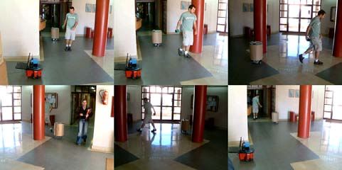
The test begins with a student pulling a perfectly round 0.8
cylinder of radius equal to the one of columns, around
0.6
two architectonic columns. Without being planned a second
student passed by the low right corner, as shown in the 0.4
sequence of photographs in Fig. 10. 0.2
One challenge is to detect correctly the mobile cylinder
0
in all the course; right now false positive of benches happen 0 50 100 150 200 250
Iteraction
when the mobile cylinder is at a distance from the other
cylinders equal to the bench distance. Fig. 8. Computational times for detection of lines and circles for the
static and the dynamic tests
C. Results
The temporal sequence of snapshots in Fig.7 shows lines
perfectly detected, this result is observed during the whole with at least 3 points. One way to compensate this loss
test. of detail is increasing the laser angular resolution to 0.25◦ .
The results in Fig. 11 show that the circle detection
(green circumferences) was accurate, and no objects in the D. Computational Time
background were misdetected as circles. Scene interpreta- The plot in Fig. 8 illustrates the computational time re-
tion is executed so that the architectonic entities (walls, quired to identify all lines and circles in every iteration (360
corners, columns, benches) present are visualized. range points). Computational time concerning leg detection
Detected legs are represented as the tiny purple circles. is not shown since the algorithm involves few calculations.
It is possible to see the tracks of both students. If the These tests were executed in the Celeron 500 Mhz laptop
environment is not crowded those tracks should suffice for equipped with 128Mb of RAM that stands on the robot.
following a person. Note that there are no detection of legs Analysing the plots we conclude: (1) line detection times
in the background, mostly in the cylinders where some false oscilates with the number of subscan divisions, i.e. corners;
positive legs could happen. (2) circle pre-requisites saves precious processing time; (3)
The consistency of leg detection decreases as the range both algorithms are fast, specially when following corridors
increases. This happens because the algorithm operates without corners; (4) the worst time for lines was 1.940ms
3945and for circles was 1.082ms. R EFERENCES
[1] Robotic Freedom by Marshall Brain, [Online],
V. C ONCLUSION AND FUTURE WORK http://marshallbrain.com/robotic-freedom.htm
[2] R.O. Duda, P.E. Hart, "Use of the Hough Transform to Detect Lines
We propose algorithms for feature detection that are and Curves in Pictures", Com. of ACM, Vol.18, No.9, pp.509-517,
computationally efficient. The Inscribed Angle Variance is 1975.
[3] D. Castro, U. Nunes, and A. Ruano, "Feature extraction for moving
a novel technique to extract features from laser range data. objects tracking system in indoor environments," in 5th IFAC/Euron
It is accurate in circle detection and very helpful detecting Symp. on Intelligent Autonomous Vehicles, Lisboa, July 5-7, 2004.
other features. [4] G. Borges,and M. Aldon, “Line Extraction in 2D Range Images for
Mobile Robotics”, Journal of Intelligent and Robotic Systems, Vol.
The Player feature detection driver provides an abstrac- 40, Issue 3, pp. 267 - 297
tion layer for top layers. Distribution in Player ensures [5] A. Mendes, and U. Nunes, "Situation-based multi-target detection and
tracking with laser scanner in outdoor semi-structured environment",
that these algorithms will be further improved and others IEEE/RSJ Int. Conf. on Systems and Robotics, pp. 88-93, 2004
methods will be added. It’s also previewed a output plugin [6] T. Einsele, "Localization in indoor environments using a panoramic
for grouping of partially occluded features by fitting points laser range finder," Ph.D. dissertation, Technical University of
München, September 2001.
to the known features parameters. Our visualization tool [7] B.P. Gerkey , R.T. Vaughan, and A. Howard (2003). The Player/Stage
PlayerGL will interpret sets of primitives for real-time 3D Project, [Online], http://playerstage.sf.net .
interpretation of trashcans, doors, chairs, etc. The final goal [8] D. Schulz, W. Burgard, D.Fox, and A.Cremers, "Tracking multiple
moving targets with a mobile robot using particle filters and statistical
is the reconstruction from laser scan data of a dynamic data association," in IEEE Int. Conf. on Robotics and Automation,
scene, with moving persons, and differentiable structures. pp.1665-1670, Seul 2001.
[9] B. Kluge, C. Köhler, and E. Prassler, "Fast and robust tracking of
multiple moving objects with a laser range finder," in IEEE Int. Conf.
on Robotics and Automation, pp.1683-1688, Seoul, 2001.
[10] A. Fod, A. Howard, and M. J. Mataric, "A laser-based people
tracker," in IEEE Int. Conf. on Robotics and Automation, pp. 3024-
3029, Washington D.C., May 2002.
[11] C-C Wang and C. Thorpe, "Simultaneous localization and mapping
with detection and tracking of moving objects," in IEEE Int. Conf.
on Robotics and Automation, pp.2918-2924, Washington D.C., 2002.
Fig. 9. Panoramic photograph of static test scenario. [12] Zhen Song, Yang Quan Chen, Lili Ma, and You Chung Chung,
"Some sensing and perception techniques for an omni-directional
ground vehicles with a laser scanner," IEEE Int. Symp. on Intelligent
Control, Vancouver, British Columbia, 2002, pp. 690-695.
[13] Sen Zhang, Lihua Xie, Martin Adams, and Tang Fan, "Geometrical
feature extraction using 2D range scanners” Int. Conference on
Control & Automation, Montreal, Canada, June 2003.
[14] Kay Ch. Fuerstenberg, Dirk T. Linzmeier, and Klaus C.J Dietmayer,
“Pedestrian recognition and tracking of vehicles using a vehicle based
multilayer laserscanner” ITS 2003, 10th World Congress on Intelligent
Transport Systems, November 2003, Madrid, Spain.
[15] K. Arras and R. Siegwart, "Feature-extraction and scene interpreta-
tion for map-based navigation and map-building, " in SPIE, Mobile
Robotics XII, vol. 3210, 1997.
[16] Euclid, “The Elements”, Book III, proposition 20,21.
Fig. 10. Temporal sequence of photographs of our static test scenario. [17] SICK, Proximity laser scanner, SICK AG, Industrial Safety Systems,
Germany, Technical Description, 05 2002.
[18] C. Ye and J. Borenstein, "Characterization of a 2-D laser scanner for
mobile robot obstacle negotiation," IEEE Int. Conference on Robotics
and Automation, Washington DC, USA, 2002, pp. 2512-2518
[19] Mathpages, Perpendicular regression of a line, [Online],
http://mathpages.com/home/kmath110.htm.
[20] OpenGL, [Online], http://www.opengl.org.
Fig. 11. Screen capture of PlayerGL at the end of the static test. The
detected mobile cylinder is represented by the green circumferences, and
legs are represented by tiny purple circles. Interpretation of walls, columns
and benches is also achieved.
3946You can also read