First operation of Transition-Edge Sensors in space with the Micro-X sounding rocket
←
→
Page content transcription
If your browser does not render page correctly, please read the page content below
First operation of Transition-Edge Sensors in space with the
                                                                 Micro-X sounding rocket
                                                       Joseph S. Adamsa , Robert Bakera , Simon R. Bandlera , Noëmie Bastidonb,h ,
                                              Meredith E. Danowskib,i , William B. Doriesec , Megan E. Eckartd , Enectalı́ Figueroa-Felicianob ,
                                                     Joshua Fuhrmanb , David C. Goldfingere,j , Sarah N.T. Heinee , Gene C. Hiltonc ,
                                                  Antonia J.F. Hubbardd,* , Daniel Jardinb , Richard L. Kelleya , Caroline A. Kilbournea ,
                                               Renée E. Manzagol-Harwoodb , Dan McCammonf , Takashi Okajimaa , Frederick S. Portera ,
                                                     Carl D. Reintsemac , Peter Serlemitsosa , Stephen J. Smitha , and Patrick Wikusg
arXiv:2103.02577v1 [astro-ph.IM] 3 Mar 2021

                                                   a
                                                      NASA Goddard Space Flight Center, 8800 Greenbelt Rd, Greenbelt, Maryland, USA
                                                             b
                                                               Northwestern University, 2145 Sheridan Road, Evanston, Illinois, USA
                                                c
                                                  National Institute for Standards and Technology, 325 Broadway, Boulder, Colorado, USA
                                                d
                                                  Lawrence Livermore National Laboratory, 7000 East Avenue, Livermore, California, USA
                                              e
                                                Massachusetts Institute of Technology, 77 Massachusetts Avenue, Cambridge, Massachusetts,
                                                                                               USA
                                                          f
                                                            University of Wisconsin, 1150 University Avenue, Madison, Wisconsin, USA
                                                                g
                                                                  Bruker Biospin, Industriestrasse 26, 8117 Fällanden, Switzerland
                                                   h
                                                     Current affiliation: The Australian National University, Canberra ACT 0200, Australia
                                                     i
                                                       Current affiliation: Ball Aerospace, 1600 Commerce Street, Boulder, Colorado, USA
                                                 j
                                                   Current affiliation: Harvard and Smithsonian Center for Astrophysics, 60 Garden Street,
                                                                                  Cambridge, Massachusetts, USA

                                                                                               ABSTRACT
                                              With its first flight in 2018, Micro-X became the first program to fly Transition-Edge Sensors and their SQUID
                                              readouts in space. The science goal was a high-resolution, spatially resolved X-ray spectrum of the Cassiopeia A
                                              Supernova Remnant. While a rocket pointing error led to no time on target, the data was used to demonstrate
                                              the flight performance of the instrument. The detectors observed X-rays from the on-board calibration source,
                                              but a susceptibility to external magnetic fields limited their livetime. Accounting for this, no change was observed
                                              in detector response between ground operation and flight operation. This paper provides an overview of the first
                                              flight performance and focuses on the upgrades made in preparation for reflight. The largest changes have been
                                              upgrading the SQUIDs to mitigate magnetic susceptibility, synchronizing the clocks on the digital electronics
                                              to minimize beat frequencies, and replacing the mounts between the cryostat and the rocket skin to improve
                                              mechanical integrity. As the first flight performance was consistent with performance on the ground, reaching
                                              the instrument goals in the laboratory is considered a strong predictor of future flight performance.
                                              Keywords: microcalorimeter; transition-edge sensor; sounding rocket; x-ray spectroscopy

                                                 *Address correspondence to Antonia J.F.Hubbard: hubbard8@llnl.gov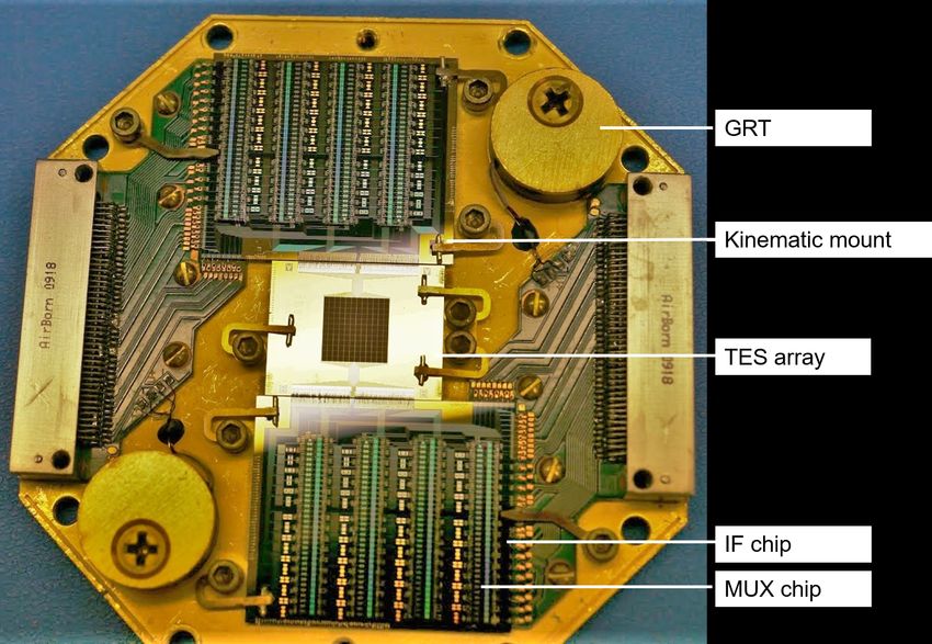
1. INTRODUCTION
Micro-X is a sounding rocket mission designed to obtain high-resolution spectra of extended X-rays sources.
It is also intended to further the technology readiness of Transition-Edge Sensor (TES) microcalorimeters and
Superconducting QUantum Interference Devices (SQUIDs) for space operation. The instrument must fly on a
sounding rocket because X-rays in the signal bandpass are attenuated by the atmosphere. Sounding rockets
are suborbital missions, and each flight provides approximately five minutes of observation above an altitude of
160 km. Sounding rockets provide a good testbed for new technologies, as with Micro-X, because the instrument
can be recovered after flight, providing the opportunity to modify the instrument for any future flights. Special-
ized engineering is required to successfully operate sensitive detectors, like microcalorimeters, in the vibrationally
intense and time-constrained conditions of a sounding rocket flight.1, 2
    This paper reviews the design (§2) and performance (§3) of the instrument in the first flight, with particular
emphasis on the impact of external magnetic fields (§3.1) and instrument configuration (§3.2) on performance.
The instrument performance in flight and post-flight testing drove the modifications that have been implemented
in preparation for the reflight (§4). A comprehensive description of the instrument and first flight performance
are provided in.1

                                   2. FIRST FLIGHT INSTRUMENT
The Micro-X instrument, shown in Figure 1, combines an X-ray mirror and a TES microcalorimeter array to
achieve the instrument specifications provided in Table 1. Astronomical X-rays are focused by the X-ray mirror
onto the detector array, which sits inside the cryostat. The detectors require a pumped liquid helium Adiabatic
Demagnetization Refrigerator (ADR) to maintain a stable 75 mK ± 10 µK operating temperature. The on-board
electronics maintain the instrument operating conditions by executing flight operations and running the control
loops for the ADR and SQUIDs.

Figure 1. X-rays enter the Micro-X instrument from the aft side (right in figure). They are focused by the X-ray mirror
onto the detector array. The array sits inside the cryostat, with temperature control maintained by the pumped liquid
helium ADR. On-board electronics control the state of the system and read out data.

                                                          Parameter                               Specification
   The detector array is comprised of 128 TES mi-
crocalorimeter pixels.3, 4 Microcalorimeters measure      Array   size                            7.2×7.2 mm2
X-ray energy by tracking the temperature of an X-         Effective  area   (1 keV)               300  cm2
ray absorber. The absorber heats up when hit by an        Field  of view                          11.8’
X-ray, then it cools down as heat dissipates through      Angular resolution (HPD)                2.4 arcminutes
a weak thermal link into a cold bath. The rise and        Energy    bandpass                      0.3 - 2.5 keV
decay times of the thermal pulse are engineered when      Quantum      efficiency (0.2 - 4.0 keV) ∼100%
designing the pixel, and the pulse height (i.e., temper-  Spectral resolution (0.2 - 3.0 keV) 4.5 – 11 eV
                                                         Table 1. The Micro-X instrument specifications are optimized
ature rise) is proportional to the X-ray energy.
                                                           for high-resolution observations of extended X-ray sources.
TESs are thin, superconducting films that are biased into the transition region between their superconducting
and normal states. In this regime, a small change in the temperature of the absorber leads to a large change
in resistance of the TES, providing a high-resolution temperature measurement. Each Micro-X pixel uses a
140×140 µm2 Mo/Au TES to track the temperature of a 590×590 µm2 Bi/Au absorber.
The TES array is read out with SQUIDs, which are low-noise, magnetically sensitive current amplifiers. A
three-stage DC SQUID Time-Division Multiplexing (TDM) readout scheme amplifies the TES signals to a level
compatible with the room temperature electronics.5–7 The TES array is divided into two independent, 64-pixel
TDM readout chains, each with four “columns” of 16 “rows.”7 The biases to the first-stage SQUIDs (SQ1) are
cycled sequentially to turn on one row at a time. All 16 SQ1s in a column are connected in series to a summing
coil, which couples the signal from the biased SQ1 to the second-stage SQUID (SQ2). The signal from the SQ2
is amplified by the third-stage Series Array (SA), which amplifies the signal by a factor of 100 before it reaches
the room-temperature electronics. The room-temperature electronics bias each component, process the digital
feedback loops for the SQUIDs, and record the science data.
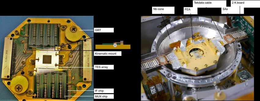
The TES array and the first two SQUID
stages (SQ1 and SQ2) are kinematically
mounted to the Front End Assembly (FEA),
shown in Figure 2. The TES array sits on a chip
in the center of the FEA. The SQ1 and SQ2 are
lithographically fabricated onto a set of multi-
plexer (MUX) chips. The MUX chips are glued
to an interface (IF) chip, which holds bandwidth-
limiting inductors and shunt resistors. There
are two sets of MUX and IF chips, one for each
science chain. The FEA base is a magnesium
plate that is thermally connected to the ADR
salt pill to maintain a stable operating tempera-
ture. Two Germanium Resistance Thermome-
ters (GRTs) are used for temperature control
and monitoring.
The FEA must be shielded from infrared ra-
Figure 2. The FEA holds the TES array and the first two SQUID
diation, vibration, and magnetic fields. Six in- stages. The GRTs are used by the ADR to keep the FEA at a
frared blocking filters sit between the FEA and stable 75 mK.
the cryostat aperture. They minimize the trans-
mission of blackbody radiation from the warmer
stages of the instrument while allowing 78% of X-rays through.1 Three stages of vibration isolation keep heat
from coupling into the detector thermal stage during flight. These stages include: (1) wire rope isolators that
mount the cryostat to the rocket (44 Hz resonant frequency); (2) G10 plastic tubes that support the liquid helium
tank inside the cryostat (96 Hz resonant frequency); (3) Kevlar suspension that hangs the detectors from the
liquid helium tank (325 Hz resonant frequency).8 The increasingly high frequencies of the inner stages dampen
the outer stages for an effective isolation scheme.
TESs and SQUIDs are sensitive to magnetic fields, and three stages of shielding minimize the effective field
at the detector array, due to both the Earth’s magnetic field and the ADR magnet. An external field coupling
into the SQUIDs can move their response away from their stable operating point, and even outside the range of
their flux-locked loops. The SQ2 stage is projected to have a larger magnetic susceptibility than the SQ1 stage
due to the difference in their effective areas (468.5 µm2 and 5.0 µm2 , respectively).9 The first stage of magnetic
shielding is a bucking coil between the ADR magnet and the FEA. The second stage is a superconducting Nb can
that surrounds the FEA to reject external magnetic fields through the Meissner-Ochsenfeld effect.10 In addition
to the openings for X-ray entry and the thermally conductive rod to the ADR, the shield has two holes for
harnessing to the FEA. The final stage of shielding is a field coil inside the Nb shield to counteract any trapped
static field. It was not used in the first flight. The SA are not mounted on the FEA; they are mounted at the
2 K stage, and a separate Nb box surrounds them. In addition to these shielding layers, a removable Metglas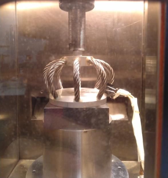
blanket is wrapped around the cryostat each time it is cooled down from room temperature. This is done to
minimize the amount of the Earth’s magnetic field that freezes into the Nb shield when it goes superconducting.
    To monitor detector response in flight, a radioactive calibration source inside the cryostat provides a con-
tinuous source of X-rays just outside the science band. It is mounted on the inside of the Nb can lid, roughly
1 cm from the detector array. The calibration source uses a ring of 55 Fe to illuminate a KCl scintillator ring,
producing Cl and K lines. The source rate in flight was measured to be 0.7 counts/pixel/s, corresponding to a
K-Kα rate of 0.23 ± 0.06 counts/pixel/s.
   The rocket payload includes both the science instrument and several standard payload systems that are
supplied by the NASA Sounding Rocket Operations Contract (NSROC).11 These systems include the celestial
Attitude Control System (ACS) for pointing, the S-19 boost guidance system for trajectory control, the Ogive
Recovery System Assembly (ORSA) to control the descent, and three telemetry systems for data transmission.

                                                             3. FLIGHT PERFORMANCE
Micro-X launched from the White Sands Missile Range in New Mexico at midnight on July 22, 2018. The science
target was the Cassiopeia A Supernova Remnant. In flight, an ACS failure led the payload to spin and not spend
any time on target. Despite this, the flight data was used to analyze the performance of the instrument. All flight
operations were successfully executed, and the full data stream was recovered from on-board flash memory. The
instrument achieved a stable 75 mK environment during the science observation, demonstrating the successful
performance of both the ADR and the vibration isolation system. Despite the lack of a bright astrophysical
target, the flight performance of the detectors was analyzed with X-rays from the calibration source (§3.1–3.2).
Details on the flight performance can be found in.1
   The rocket launched with the instrument in a protected configuration. The ADR was holding at 300 mK to
maximize the available cooling power, and the instrument was closed off to space. The shutter door to the optics
was closed, as was the aperture valve on the cryostat that exposes the detector array to the optics. Figure 3
shows that no discernible heat coupled into the detector stage (top) during powered flight (bottom). Once the
payload was through powered flight, timer commands were sent to the instrument electronics to prepare for
the science observation. The ADR began tight temperature control at 75 mK, and the apertures to the optics
and the cryostat opened to expose the detector array to space. This was the start of the science observation.
The observation lasted for 320 s, after which point the apertures closed in preparation for atmospheric re-entry.
An apparent heat deposition during re-entry, likely from a glue failure in the wire rope isolators (§4.2), was
successfully mitigated by the ADR, and tight temperature control was then maintained until impact. At 4.6 km
above the ground, the parachute deployed for the remainder of the descent.

          Powered flight Regulate
                                     Launch    Open valves                           Close valves                       Impact
                                                             Science observation             Re-entry   Chute descent
                                                    No temperature change
        acceleration [g] temp [mK]

                                     300
                          Detector

                                     200
                                                                75 mK ± 5 μK
                                     100
                                       0

                                      10           13.4 g max
                                       5
            Thrust

                                       0
                                      -5
                                           0      100         200       300          400          500   600       700
                                                                    Time [s from launch at t = 0]

Figure 3. The thermal performance of the instrument was successful. The detector stage was launched at 300 mK, and
no discernible heat coupled into the stage during powered flight, which saw 13.4g thrust acceleration on the exterior of
the rocket. Stable temperature regulation of 75 mK±5 µK was achieved during the science observation.

            SPIE AS20 – December 2020                                     Antonia Hubbard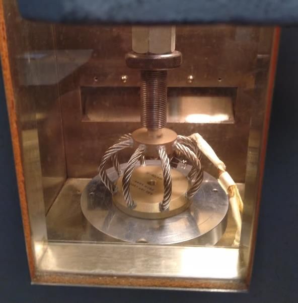
3.1 SQUID magnetic susceptibility
The magnetic susceptibility of the SQUIDs to the Earth’s field was illustrated using data from powered flight,
when the TESs were normal. During this period, the rocket was spinning in the Earth’s magnetic field, as
measured by an on-board three-axis magnetometer. The SQUIDs response during this stage tracked the magne-
tometer reading, demonstrating a magnetic susceptibility, likely at the SQ2 stage. The SQUIDs were the most
                                                                                Title Text
susceptible to the Earth’s field in the direction of the holes in the superconducting Nb shield for FEA harnessing,
shown in Figure 4.
    The external magnetic field moved some SQUIDs                                      Harnessing
far enough from their operating points that they un-           Nb shield         FEA                SAs
locked, meaning that they effectively stopped reading
out. This unlocking is qualitatively consistent with
models simulating the response of the 3-stage SQUID
readout to magnetic fields.1 Under a normal flight tra-
jectory, the payload would have been effectively sta-
tionary during the science observation. Due to the
ACS failure, the payload continued to tumble through-
out the science observation, so the SQUIDs continued
to experience a changing field. As a result of this
unlocking, the science observation had an exposure
equivalent to 118 seconds of the full array.
    This magnetic susceptibility was confirmed with
post-flight Helmholtz coil testing. The coils were
placed along three orthogonal axes around the exte-
rior of the rocket skin, with a magnetometer record-
ing the applied field. They simulated spinning in the
                                                    SPIE AS20 – December 2020          Antonia Hubbard                  2
                                                            Figure 4. A superconducting Nb magnetic shield surrounds
Earth’s field by sweeping the magnetic field by one the FEA. The SQUIDs exhibited the largest magnetic sus-
Earth field in either direction. The SAs were not dis- ceptibility in the direction of the holes in the shielding for
cernibly susceptible to the external field, indicating the harnessing.
successful magnetic shielding at the SAs. Testing of
the entire 3-stage SQUID readout demonstrated that
a large fraction of the SQUIDS reliably unlocked when exposed to simulated spinning. In addition to the field
strength, a strong dependence on the speed of the magnetic field change (dB/dt) was observed. A gradual
progression up to one Earth field moved the average composite SQUID response by 0.1Φ0 , where Φ0 represents
one period in the oscillatory SQUID response. By contrast, a discrete jump from no field to three Earth fields
shifted the average composite SQUID response by 0.7Φ0 . When the Helmholtz coils returned to zero field, the
SQUID response did not return to its original position, but showed a significantly hysteretic response. This
complicates comparisons to flight data. The susceptibility in the direction of the holes in the Nb shield was not
probed directly; the closest measurement was clocked 22.5◦ from that direction. This was the most susceptible
of the measured directions, consistent with the flight observation that the most susceptible direction was that of
the Nb shield holes.

3.2 System noise
Integrating the instrument impacted detector performance, as described in detail in.1 The fundamental detector
resolution, in ideal laboratory conditions, was measured to be 4.5 eV. When running with one flight science chain,
the average resolution of across the array was 6.5 eV, with 104 of the 116 active pixels achieving resolutions
better than 10 eV. The instrument was then integrated, which means that the electronics were mounted above
the cryostat and both science chains were turned on. In this configuration, the average resolution across the
array increased to 11 eV, with 41 pixels achieving resolutions better than 10 eV. Figure 5 shows the difference
in the two configurations for one pulse (YA07), which saw a moderate increase in system noise. A second pixel
(YA08) picked up higher levels of system noise, with a corresponding degradation in resolution. A significant
portion of the degradation is hypothesized to be from non-stationary noise due to beating between the clocks of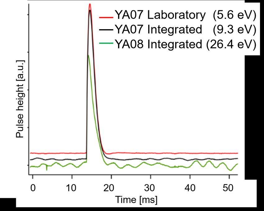
the two science chains. Each science chain received its own clock from an MV encoder, and these clocks were
not synchronized for the first flight.
   The flight performance is consistent with the ground performance in the integrated configuration, excluding
the magnetic field effects described in §3.1. No change to the noise spectrum or pulse shape was observed between
the two datasets, as shown for a single pixel in Figure 5. Additionally, no change in the noise spectrum or pulse
shape was observed in flight between the array being open to space and the apertures to space being closed. This
implies that performance improvements implemented on the ground are likely to predict flight performance.
    Post-flight noise testing was consistent with the hypoth-
esis that the science chain clocks were largely responsible
for the observed beating. Laboratory testing used encoder
simulators rather than the flight MV encoders, introducing
uncertainty in the predicted flight response based on this
testing. The beating observed in flight was qualitatively
reproduced with the encoder simulators, and it was only
observed when both simulators were on. It was mitigated
by feeding a single clock into both simulators, effectively
synchronizing them. The laboratory setup used for this syn-
chronization test introduced additional noise to the system
during the test, so no measurement was made of the impact
of this synchronization on the total noise floor. The MV en-
coders have been synchronized for the reflight, as described
in §4.2. A definitive statement on the impact of this syn-
chronization on detector performance will be made once the Figure 5. Pre-flight testing showed changes in detector
payload is fully integrated for the reflight.                 performance, presumably driven from beating between
                                                              the two science chain clocks, once the instrument was
         4. SECOND FLIGHT SYSTEM                              integrated. YA07 shows a moderate change in noise be-
                                                              tween the configurations, while YA08 shows significant
Modifications to the instrument were motivated by perfor-     noise. Post-flight testing confirmed that synchronizing
mance in flight and in post-flight testing. To address the    the science chain clocks mitigates the observed beating.
magnetic susceptibility of the SQUIDs, a newer generation     The pulses have been offset for clarity.
of MUX chips was installed on the FEA, and the material
was changed for both the FEA kinematic mounts and the
spacer in the superconducting Nb magnetic shield (§4.1).
To address system noise, the clocks on both science chains were synchronized, and to avoid thermal failure, the
wire rope isolators were replaced with a higher temperature version of the same model (§4.2). Each of these
modifications has been implemented.

4.1 Magnetic Susceptibility Changes
The MUX chips have been upgraded from NIST MUX06a to NIST MUX18b, which have a demonstrated lower
magnetic susceptibilty.12 The new readout scheme is shown in Figure 6. It uses flux-activated SQUIDs in the
SQ1 stage, rather than the current-activated SQ1s used in the MUX06a sheme. The TES array is the same as
the first flight. The impact of the new SQUIDs on the noise floor is under investigation.
   In addition to the MUX chip replacement, the kinematic mounts that hold the TES and SQUID chips were
replaced. The first flight kinematic mounts were made of tungsten carbide, which had become magnetized. The
new mounts are made of sapphire. There is no indication that the old mounts impacted performance, but the
modification was made to prevent any possible impact.
    The spacer on the inside of the superconducting Nb magnetic shield was replaced to improve the efficacy of
the shield. The first flight spacer was made of stainless steel. It was replaced with Pb, which is superconducting
at the instrument’s operating temperature. The Nb is designed cover the entire spacer, but this replacement will
provide a more robust magnetic shield if there are any gaps in the Nb layer.
These three changes were implemented at the same time, and
the combination of these changes significantly reduced the SQUID
susceptibility to external magnetic fields. The Helmholtz coil test-
ing that unlocked the first flight SQUIDs in the simulated Earth’s
magnetic field did not unlock the new SQUIDs. Introducing an ex-
ternal field equivalent to one Earth field moved the SQUID response
by 0.016Φ0 . The SQUIDs maintained a stable lock throughout test-
ing. The SQUID response is independent of the rate of the change
of the magnetic field, and no hysteresis is observed. The tests were
performed with the TESs both on and off; no difference was ob-
served between configurations. If the flight performance continues
to follow the ground performance, these SQUIDs are not projected
to unlock in flight.
4.2 Additional Changes
The MV encoder clocks were synchronized to eliminate the beating
noise that degraded detector performance in the integrated configu-
ration (§3.2). The telemetry engineers at the Wallops Flight Facility
synchronized the encoders, and the new system passed handshake
testing with the instrument electronics. Micro-X will be the first
program to fly synchronized MV encoders. The impact of the syn-
chronization on detector performance will be measured once the
payload is integrated for the next flight.
The wire rope isolators that mount the cryostat to the rocket
Figure 6. The MUX18b readout scheme uses skin experienced the only mechanical failure of the flight. The glue
flux-activated switches in the SQ1 stage and
on the isolators is presumed to have failed due to its thermal contact
has demonstrated lower magnetic susceptibil-
with the rocket skin. This failure was reproduced in thermal testing
ity than the MUX06a flown in the first Micro-
X flight. Image from.12 in the laboratory after flight. The force required to compress the
isolators by 1 mm was measured at 10◦ C intervals from 20–170◦ C,
and the response was observed to degrade above 60◦ C. In flight, the
skin reached 60◦ C during powered flight, and it stayed above this
ture effect
temperature through impact. The isolators were therefore replaced with a higher-temperature-rated version of
the same model to maintain their effectiveness as part of the vibration isolation scheme. The new isolators passed
thermal testing up to 170◦ C. This is acceptable for flight, as the rocket skin reached a maximum temperature of
110◦ C in the first flight. NEW
Title Text
Temperature effect NEW
First flight isolators
Reflight isolators
240
Load for 1 mm displacement [N]
230
220
210
200
190
OLD
20 40 60 80 100 120 140 160
Temperature [°C]
SPIE AS20 – December 2020 Antonia Hubbard
Figure 7. The new wire rope isolators maintain a constant response up to 170◦ C in laboratory testing. This is a significant
improvement over the first flight isolators’ response, which degraded above 60◦ C. The rocket skin reached 110◦ C in flight.5. CONCLUSIONS
The maiden flight of Micro-X saw the first operation of TESs and SQUIDs in space. Despite the ACS failure,
the flight provided a measurement of the instrument flight performance. The flight operations and a number of
instrument systems, notably the cryogenic system, had nominal performance. These systems are anticipated to
fly again without any changes. The instrument flight performance was impacted by the magnetic susceptibility
of the SQUIDs, increased system noise when the instrument was integrated, and the mechanical failure of the
wire rope isolators. Each of these issues has been addressed by modifications in preparation for the next flight.
The SQUIDs’ magnetic susceptibility was addressed with a combination of new SQUIDs and material selec-
tion. The MUX chips were upgraded to NIST MUX18b. The kinematic mounts were converted from tungsten
carbide to sapphire, and the spacer in the superconducting Nb magnetic shield was converted from stainless
steel to lead. These changes were made at the same time, and the combination of them decreased the magnetic
susceptibility to the point that the SQUIDs are not projected to unlock in future flights. The system noise was
addressed by synchronized the encoder clocks that supply the clocks for the science chains. The wire rope isolator
failure was addressed by replacing them with a higher-temperature-rated version of the same model. As the flight
performance was consistent with the ground performance in the first flight, the ground performance following
these upgrades is expected to predict future flight performance. Work is underway to characterize the noise
performance of the system with the new SQUIDs, and the system will then move towards flight integration.
REFERENCES
[1] Adams, J. S., Baker, R., Bandler, S. R., Bastidon, N., Castro, D., Danowski, M. E., Doriese, W. B., Eckart,
M. E., Figueroa-Feliciano, E., Fuhrman, J., Goldfinger, D. C., Heine, S. N. T., Hilton, G. C., Hubbard,
A. J. F., Jardin, D., Kelley, R. L., Kilbourne, C. A., Manzagol-Harwood, R. E., McCammon, D., Okajima,
T., Porter, F. S., Reintsema, C. D., Serlemitsos, P., Smith, S. J., and Wikus, P., “First Flight Performance
of the Micro-X Microcalorimeter X-Ray Sounding Rocket,” in preparation (2021).
[2] McCammon, D., Almy, R., Apodaca, E., Bergmann Tiest, W., Cui, W., Deiker, S., Galeazzi, M., Juda, M.,
Lesser, A., Mihara, T., Morgenthaler, J. P., Sanders, W. T., Zhang, J., Figueroa-Feliciano, E., Kelley, R. L.,
Moseley, S. H., Mushotzky, R. F., Porter, F. S., Stahle, C. K., and Szymkowiak, A. E., “A high spectral
resolution observation of the soft x-ray diffuse background with thermal detectors,” The Astrophysical
Journal 576, 188–203 (2002).
[3] Eckart, M. E., Adams, J. S., Bandler, S. R., Brekosky, R. P., Brown, A., Chervenak, J. A., Ewin, A. J.,
Finkbeiner, F. M., Kelley, R. L., Kilbourne, C. A., Porter, F. S., Sadleir, J. E., Smith, S. J., Figueroa-
Feliciano, E., and Wikus, P., “Large-Absorber TES X-ray Microcalorimeters and the Micro-X Detector
Array,” in [The Thirteenth International Workshop on Low Temperature Detectors—LTD13 ], Young, B.,
Cabrera, B., and Miller, A. J., eds., American Institute of Physics Conference Series 1185, 699–702 (Dec.
2009).
[4] Eckart, M. E., Adams, J. S., Bandler, S. R., Busch, S. E., Chervenak, J. A., Ewin, A. J., Finkbeiner,
F. M., Kelley, R. L., Kilbourne, C. A., Porter, F. S., Porst, J. ., Sadleir, J. E., Smith, S. J., Wassell, E. J.,
and Figueroa-Feliciano, E., “Development of tes microcalorimeter arrays for the micro-x sounding rocket
experiment,” IEEE Transactions on Applied Superconductivity 23(3), 2101705–2101705 (2013).
[5] Chervenak, J. A., Grossman, E. N., Irwin, K. D., Martinis, J. M., Reintsema, C. D., Allen, C. A., Bergman,
D. I., Moseley, S. H., and Shafer, R., “Performance of multiplexed SQUID readout for Cryogenic Sensor
Arrays,” Nuclear Instruments and Methods in Physics Research A 444, 107–110 (Apr. 2000).
[6] de Korte, P. A. J., Beyer, J., Deiker, S., Hilton, G. C., Irwin, K. D., Macintosh, M., Nam, S. W., Reintsema,
C. D., Vale, L. R., and Huber, M. E., “Time-Division Superconducting Quantum Interference Device Mul-
tiplexer for Transition-Edge Sensors,” Review of Scientific Instruments 74, 3807–3815 (Aug. 2003).
[7] Reintsema, C. D., Adams, J. S., Baker, R., Bandler, S. R., Doriese, W. R., Figueroa-Feliciano, E., Hilton,
G. C., Irwin, K. D., Kelly, R. L., Kilbourne, C. A., Krinsky, J. W., Porter, F. S., and Wikus, P., “Electronics
for a Next-Generation SQUID-Based Time-Domain Multiplexing System,” in [The Thirteenth International
Workshop on Low Temperature Detectors—LTD13], Young, B., Cabrera, B., and Miller, A. J., eds., Amer-
ican Institute of Physics Conference Series 1185, 237–240 (Dec. 2009).[8] Danowski, M. E., Heine, S. N. T., Figueroa-Feliciano, E., Goldfinger, D., Wikus, P., McCammon, D., and
Oakley, P., “Vibration Isolation Design for the Micro-X Rocket Payload,” Journal of Low Temperature
Physics , 1–7 (2016).
[9] Stiehl, G. M., Cho, H. M., Hilton, G. C., Irwin, K. D., Mates, J. A. B., Reintsema, C. D., and Zink,
B. L., “Time-Division SQUID Multiplexers With Reduced Sensitivity to External Magnetic Fields,” IEEE
Transactions on Applied Superconductivity 21, 298–301 (June 2011).
[10] Meissner, W. and Ochsenfeld, R., “Ein neuer effekt bei eintritt der supraleitfähigkeit,” Naturwis-
senschaften 21(44), 787–788 (1933).
[11] SRPO, [NASA Sounding Rockets User Handbook ], NASA Goddard Space Flight Center, Wallops Island,
VA (2015).
[12] Reintsema, C. D., Bennett, D. A., Denison, E. V., Durkin, M., Doriese, W. B., Fowler, J. W., Gard, J. D.,
Grigorian, A., Hilton, G. C., Hubmayr, J., O’Neil, G. C., Mates, J. A. B., Morgan, K. M., Schmidt, D. R.,
Stevens, R. W., Swetz, D. S., Vale, L. R., Ullom, J. N., Irwin, K. D., Chaudhuri, S., Titus, C. J., and
Dawson, C. S., “High-throughput, dc-parametric evaluation of flux-activated-switch-based tdm and cdm
squid multiplexers,” IEEE Transactions on Applied Superconductivity 29(5), 1–6 (2019).
ACKNOWLEDGMENTS
We gratefully acknowledge the technical support of Ernie Buchanan, John Bussan, Travis Coffroad, Sam Gabelt,
Rob Hamersma, Kurt Jaehnig, Frank Lantz, Ken Simms, Tomomi Watanabe, George Winkert, and the WFF
team. Micro-X operates under NASA Grant 80NSSC18K1445. Part of this work was performed under the
auspices of the U.S. Department of Energy by Lawrence Livermore National Laboratory under Contract DE-
AC52-07NA27344.You can also read