IMPROVEMENT OF LONG-TERM CYCLING PERFORMANCE OF HIGH-NICKEL CATHODE MATERIALS BY ZNO COATING
←
→
Page content transcription
If your browser does not render page correctly, please read the page content below
Nanotechnology Reviews 2021; 10: 210–220
Research Article
Fangfang Wang, Ruoyu Hong*, Xuesong Lu, Huiyong Liu, Yuan Zhu, Ying Zheng, and David Hui
Improvement of long-term cycling performance of
high-nickel cathode materials by ZnO coating
https://doi.org/10.1515/ntrev-2021-0020
received March 17, 2021; accepted April 1, 2021
1 Introduction
Abstract: The high-nickel cathode material of LiNi0.8Co0.15 Since the first successful development and commerciali-
Al0.05O2 (LNCA) has a prospective application for lithium-ion zation of lithium-ion batteries (LIBs) by Sony in Japan in
batteries due to the high capacity and low cost. However, 1991, LIB have received increasing attention [1]. Due to
the side reaction between the electrolyte and the electrode the high energy density, good cycling performance, and
seriously affects the cycling stability of lithium-ion batteries. environmental friendliness [2], LIBs have become one of
In this work, Ni2+ preoxidation and the optimization of cal- the most promising green secondary batteries in the
cination temperature were carried out to reduce the cation twenty-first century [3]. As an important component of
mixing of LNCA, and solid-phase Al-doping improved the LIBs, the cathode material has much lower capacity than
uniformity of element distribution and the orderliness of the anode material, accounting for the highest proportion
the layered structure. In addition, the surface of LNCA
of battery cost [4]. However, the initial Coulombic effi-
was homogeneously modified with ZnO coating by a facile
ciency, rate capability, and cycling performance of these
wet-chemical route. Compared to the pristine LNCA, the
LiNiO2-based cathode materials are not satisfactory, espe-
optimized ZnO-coated LNCA showed excellent electroche-
cially at an elevated temperature [5]. Therefore, research
mical performance with the first discharge-specific capacity
on high-capacity cathode materials plays a crucial role in
of 187.5 mA h g−1, and the capacity retention of 91.3% at
the development of LIBs [6].
0.2C after 100 cycles. The experiment demonstrated that
Among the layered materials, LiNi0.8Co0.15Al0.05O2 is
the improved electrochemical performance of ZnO-coated
a promising cathode material, which is due to the com-
LNCA is assigned to the surface coating of ZnO which pro-
bination of the advantages of high theoretical capacity
tects LNCA from being corroded by the electrolyte during
and stable layered structure of LiNiO2 [7], LiCoO2 [8],
cycling.
and LiAlO2 [9]. As the precursor of LiNi0.8Co0.15Al0.05O2,
Keywords: LiNi0.8Co0.15Al0.05O2, cathode material, ZnO Ni0.8Co0.15Al0.05(OH)2.05 is generally prepared by copreci-
coating, lithium-ion battery pitation method [10]. However, the Ksp of Al(OH)3 (4.57 ×
10−33) is much less than that of Ni(OH)2 (2 × 10⁻¹⁵) and Co
(OH)2 (1.58 × 10⁻¹⁵), meaning that the ions of Al3+ preci-
pitate faster with the hydroxide, which inhibits the uniform
growth of the precursor [11]. The generated precipitate
will undergo a lattice change and structural collapse
during the cycling [12]. In the traditional preparation pro-
cess, the oxidation of Ni2+ was carried out during the
* Corresponding author: Ruoyu Hong, College of Chemical calcination [13]. However, the agglomeration of materials
Engineering, Fuzhou University, Fujian 350000, Fuzhou, China,
could make it difficult for the internal Ni2+ to be oxidized
e-mail: rhong@fzu.edu.cn
Fangfang Wang, Huiyong Liu: College of Chemical Engineering, to N3+, resulting in cation mixing [14]. The radius of Ni2+
Fuzhou University, Fujian 350000, Fuzhou, China is very close to Li+, and the 3b of Ni2+ will occupy the 3a of
Xuesong Lu: School of Engineering and Physical Sciences, Li+ [15], which hinders the deintercalation of Li+ and
Heriot-Watt University, Edinburgh EH14 4AS, United Kingdom further affects the cycling performance. In addition, the
Yuan Zhu: EVE Energy Co., Ltd., Huizhou 516100, China
Ni-containing cathodes easily react with electrolyte and
Ying Zheng: Department of Chemical and Biochemical Engineering,
Western University, London, ON, N6A 5B9, Canada
the transition metal ions dissolve due to HF corrosion
David Hui: Department of Mechanical Engineering, University of [16]. The unstable Ni4+ ions in the charged state tend to
New Orleans, New Orleans, LA 70148, United States of America transform to more stable NiO on the cathode surface,
Open Access. © 2021 Fangfang Wang et al., published by De Gruyter. This work is licensed under the Creative Commons Attribution 4.0
International License.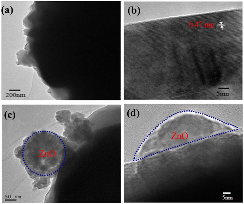
Improvement of cathode material performance by ZnO coating 211
which results in high interfacial resistance and rapid the uniformity of element distribution and the orderli-
capacity decay [17]. Moreover, the oxygen is released ness of the layered structure. In addition, the surface of
during the structural transition, causing poor safety per- LiNi0.8Co0.15Al0.05O2 was coated with ZnO [27,28] which
formance of the battery [18]. Therefore, it is urgent for us improved the structural stability and cycling perfor-
to find a new strategy to solve these problems. mance. The preparation process of ZnO-coated LiNi0.8-
Doping aluminum has been found very effective to Co0.15Al0.05O2 is shown in Figure 1.
improve durability of LIBs because it stabilizes the charge-
transfer impedance on the cathode. Much more effects
have been paid to solve the problem of rapid precipitation
of Al3+. Trease et al. [19] used a series of techniques to 2 Experimental
measure the aluminum distribution in layered LiNi0.8-
Co0.15Al0.05O2 (NCA) to investigate the influence of alu-
2.1 Preparation of LiNi0.8Co0.15Al0.05O2
minum doping on layer stabilization. The experimental
results showed that Ni3+ ions incurred a dynamic Jahn–
The NiSO4·6H2O and CoSO4·7H2O (molar ratio of 0.80:
Teller (JT) distortion, while the Al reduced the strain asso-
0.15) were dissolved in deionized water to form a mixed
ciated with JT distortion by prioritizing the electron
salt solution at a concentration of 1.9 mol L−1 and added a
ordering of the JT long bonds of Al3+ ions. A new alu-
certain amount of (NH4)2S2O8 solution. 4 mol L−1 NaOH
minum source, NaAlO2, was employed by Liang et al.
solution and 1.5 mol L−1 NH3·H2O solution are served as
[20] to prepare a high-performance LNCA (LNCA-NaAlO2).
the pH control agent and the chelating agent, respec-
NaAlO2 was hydrolyzed during the preparation of the pre-
tively. The NH3·H2O solution is first added to a 5 L reactor,
cursor to avoid the rapid precipitation of Al3+ and the
and then the salt solution and the NaOH solution are pumped
formation of flocculation precipitation. The obtained
together into the reactor at a flow rate ratio of 2:1 to react at
LNCA-NaAlO2 with uniform element distribution and orderly
50°C for 30 h; the pH was controlled at 11.00 ± 0.02 by an
layered structure showed a high initial discharge capacity
online pH meter. Then, the Ni0.8Co0.15(OH)2 was obtained
of 204.7 mA h g−1 at 0.1C and a good capacity retention of
after washing and drying. Subsequently, solid-phase Al-
74.1% after 200 cycles. Zhou et al. [21] also used AlO2− as Al
doping is used to prepare the LiNi0.8Co0.15Al0.05O2. The
source to synthesize the Ni-rich precursor, Ni0.9Co0.07Al0.03(OH)2.
Li2CO3, Ni0.8Co0.15(OH)1.9, and Al(NO3)3·9H2O (molar ratio
After optimizing the calcination conditions, LiNi0.9Co0.07Al0.03O2
of Li:Ni:Co:Al = 1.08:0.8:0.15:0.05) were mixed and ball-
demonstrated excellent electrochemical performances.
milled for 5 h, then calcined at 500°C for 5 h under the
Kim and Kim [22] used acetylacetone as a chelating agent
oxygen atmosphere in a tube furnace to obtain the inter-
to effectively control the Al reaction rate, improve the uni-
mediate product. After that, the intermediate product is
form distribution of Al, and more importantly, increase the
cooled to room temperature, ball-milled for 5 h, placed
average particle size and density of NCA. Both the volu-
in the tube furnace again, and calcined at 750°C for 12 h
metric energy and specific capacity of LIBs were increased.
in the oxygen atmosphere to form LiNi0.8Co0.15Al0.05O2.
Many methods have been reported to improve such
instable structural of high-nickel cathode material
via doping and surface coating [23,24]. Liang et al. [25]
found that the SiO2 coating onto the surface of LiNi0.8-
Co0.1Mn0.1O2 can stabilize the layered structure, effectively
reduce the corrosion of the cathode material by the elec-
trolyte, and hence, improve the cycling performance. Liu
et al. [26] used the pillaring effect of inactive Mg in the
crystal structure to modify LiNi0.8Co0.1Mn0.1O2 by doping
Mg and obtained the improved cycling stability (high-
capacity retention of 81% over 350 cycles at 0.5C).
In this work, we report the synthesis, structural
characterization, and electrochemical of ZnO-coated
LiNi0.8Co0.15Al0.05O2 cathodes. The synergistic action of
Ni2+ preoxidation by (NH4)2S2O8 and the optimization
of calcination temperature reduced the cation mixing of Figure 1: Schematic view of the synthesis process of ZnO-coated
LiNi0.8Co0.15Al0.05O2. The solid-phase Al-doping improved LiNi0.8Co0.15Al0.05O2.
212 Fangfang Wang et al.
2.2 Preparation of ZnO-coated (EIS, 100 kHz to 0.01 Hz) was performed using the same
LiNi0.8Co0.15Al0.05O2 electrochemical system.
A certain amount of Zn(AC)2·2H2O was dissolved in 40 mL
of ethanol, and after ultrasonic dissolution, 2 g of the
LiNi0.8Co0.15Al0.05O2 obtained in the above step was added 3 Results and discussion
under vigorous stirring for 4 h, and then increased to 65°C
to evaporate the ethanol. The mixture was dried at 120°C 3.1 Effect of different calcination
for 12 h, and finally calcined at 450°C for 5 h to obtain ZnO-
temperatures on LiNi0.8Co0.15Al0.05O2
coated LiNi0.8Co0.15Al0.05O2 powder which could be used
as cathode material. The amount of Zn(AC)2·2H2O added to
As known, the crystal structures and microstructures of
prepare ZnO-coated LiNi0.8Co0.15Al0.05O2 were 1, 2, 3 wt%,
LiNi0.8Co0.15Al0.05O2 are also affected by the calcination
and the prepared samples were recorded as Z1, Z2, and Z3,
temperature. Therefore, to determine the calcination tem-
respectively, and the pristine LiNi0.8Co0.15Al0.05O2 as Z0.
perature for preparing LiNi0.8Co0.15Al0.05O2, the thermo-
gravimetric analysis (TGA) was conducted in air for the
mixture Li2CO3, Ni0.8Co0.15(OH)1.9, and Al(NO3)3·9H2O (molar
2.3 Materials characterization ratio of Li:Ni:Co:Al = 1.08:0.8:0.15:0.05) in the temperature
range from 25 to 900°C, as shown in Figure 2. The differ-
The material structure was analyzed by X-ray powder ential curve is the relationship between the temperature
diffractometer (XRD, Ultima type, Japan Science) at the and the first derivative of time in the TG curve, which repre-
scanning speed of 0.2° s−1 with the scanning range of sents the weight loss rate. It can be seen that there is a
10–80°. Thermogravimetric (TG) measurements (Netzsch- slow weight loss from room temperature to 90°C, corre-
STA 449C) were conducted from room temperature to sponding to a small endothermic peak (a) on the differen-
900°C at a heating rate of 10°C min−1 in air. The surface tial curve, which is due to weight loss of absorbed water on
morphology was analyzed by scanning electron micro- surface and crystal water of Al(NO3)3. A dramatic decline
scope (SEM, Zeiss supra 55, Zeiss, Germany) and transmis- occurs from 190 to 270°C, corresponding to the maximum
sion electron microscopy (TEM, JEM-2100HR, Japan). endothermic peak of the differential curve (b), mainly
ascribed to the process of Ni0.8Co0.15(OH)1.9 forming
Ni0.8Co0.15O2. From 270 to 500°C, there is a relatively
slow weight loss, corresponding to the broad endothermic
2.4 Electrochemical measurements peak (c) on the differential curve, which is due to the
thermal decomposition of Li2CO3 to produce Li2O and
The working electrodes were prepared by mixing active release CO2. With the further increase in temperature,
material, acetylene black, and PVDF at a mass ratio of
8:1:1 in N-methylpyrrolidinone solution. The slurry was
coated onto the aluminum foil and dried at 110°C for 5 h.
Then the coated foil was pressed and punched into 14 mm
diameter disks. The electrodes were transferred to a glove
box (Super 1220/750, Mikrouna Co., Ltd. China) to assemble
in 2025 coin-type cells with a lithium foil counter electrode.
Celgard-2400 was used as the separator and 1 M LiPF6 dis-
solved in ethylene carbonate (EC) and diethyl carbonate
(DEC) (1:1 in volume ratio) as the electrolyte solution.
The galvanostatic charge and discharge cycle were
conducted on CT2001A (LAND, Bart Rui Tech. Co., Ltd.)
battery test system between 2.8 and 4.3 V (vs Li/Li+) under
different current densities. Cyclic voltammetry (CV) test was
recorded on Gamry electrochemical system (Interface1010E)
with a potential range of 3.0–4.3 V (vs Li/Li+) at a scanning Figure 2: TG–DTG curve of the mixture of Li2CO3, Ni0.8Co0.15(OH)1.9,
rate of 0.1 mV s−1. Electrochemical impedance spectrum and Al(NO3)3·9H2O.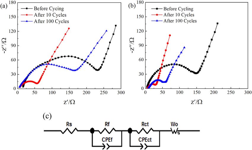
Improvement of cathode material performance by ZnO coating 213
Al2O3 was formed by decomposition of Al(NO3)3, and Table 1: Lattice parameters of LiNi0.8Co0.15Al0.05O2 prepared at dif-
finally LiNi0.8Co0.15Al0.05O2 was synthesized. The analy- ferent calcination temperatures
tical curve shows that the thermal reaction of the mixture
is carried out in stages. In order to obtain a positive Sample/°C a/Å c/Å c/a V (Å × 103) I003/I104
cathode material with excellent performance, it is neces- 700 2.86112 14.16892 4.9433 101.31 1.51
sary to strictly control the calcination conditions. In addi- 750 2.86232 14.16877 4.9421 101.23 1.79
tion, when the temperature is around 850°C, there is a 800 2.86332 14.16965 4.9488 101.87 1.52
850 2.86375 14.16433 4.9367 101.53 1.74
slow weight loss, due to the volatilization of lithium,
thereby, the calcination temperature cannot exceed 850°C.
Figure 3 shows the XRD patterns of the samples pre-
pared at different calcination temperatures. All peaks are seen that the discharge capacity generally improves with
well-indexed to the R3m group and consistent with the the increasing calcination temperature at first, and then
layered structure of α-NaFeO2 [29]. Two pairs of splitting tends to decline. The sample synthesized at 750°C has a
peaks, (006/102) and (108/110), in the XRD patterns cor- higher initial discharge-specific capacity of 186.8 mA h g−1
respond to the typical structural features of hexagonal with a capacity retention of 83.6% after 50 cycles,
layered materials [30]. None of the four samples show which is better than that of the samples prepared at
any impurity peaks, proving that the pure phase of 700°C (183.8 mA h g−1, 80.5%) and 800°C (185.8 mA h g−1,
LiNi0.8Co0.15Al0.05O2 for cathode material was synthe- 78.5%). When the temperature reached 850°C, a quick
sized. As the temperature rises, the intensity of the capacity fading is observed (from 175.3 to 137.1 mA h g−1).
(108/110) peak and (006/102) peak increases, indicating In summary, the experimental results prove that the
that the increase in the calcination temperature improves sample obtained at the calcination temperature of 750°C
the crystallinity of the samples. The lattice parameters has the best cycling performance and higher discharge-
of the four samples are shown in Table 1. It can be seen specific capacity, which is consistent with the XRD results.
that the calcination temperature has little effect on the
lattice parameters of a, c, and V, but has a certain influ-
ence on the ratio of I003/I104. In the ternary cathode mate-
rial, the ratio of I003/I104 corresponds to the internal 3.2 Effect of ZnO coating on
cation mixing, and the sample calcined at 750°C has LiNi0.8Co0.15Al0.05O2
the largest ratio of I003/I104, and the corresponding cation
mixing is the smallest. Therefore, the calcination tem- Since ZnO has relatively high electron mobility and low
perature of 750°C is the most suitable. cost, the as-prepared LiNi0.8Co0.15Al0.05O2 was coated
Figure 4 shows the cycling performance of LiNi0.8- with ZnO to improve the structural stability and cycling
Co0.15Al0.05O2 prepared at different calcination tempera- performance. Figure 5a is the XRD patterns of the Z0, Z1,
tures in the voltage range of 2.8–4.3 V at 0.2C. It can be Z2, and Z3, showing that the XRD patterns of the four
200
Discharge capacity/mAhg-1
160
120
80
700 °C
750 °C
40
800 °C
850 °C
0
0 10 20 30 40 50
Cycle number
Figure 3: XRD pattern of LiNi0.8Co0.15Al0.05O2 prepared at different Figure 4: Cycling performance of LiNi0.8Co0.15Al0.05O2 prepared at
calcination temperatures. different calcination temperatures.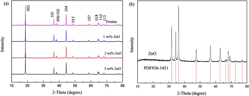
214 Fangfang Wang et al.
samples are basically the same. Compared with the stan- Table 2: Lattice parameters of pristine and ZnO-coated
dard XRD pattern of ZnO (Figure 5b), there is no charac- LiNi0.8Co0.15Al0.05O2 samples
teristic peak of ZnO appeared in the XRD pattern of Z1, Z2,
and Z3 because the amount of ZnO used in modification Sample a/Å c/Å c/a V (Å3) I003/I104
is very small and beyond the XRD resolution. The lattice Z0 2.866232 14.16877 4.9433 101.31 1.79
parameters of the four samples are listed in Table 2. Z1 2.866239 14.16253 4.9430 101.37 1.81
There is no significant change in the lattice constants Z2 2.86210 14.17036 4.9435 101.46 1.89
Z3 2.86256 14.17508 4.9440 101.57 1.83
for pristine (Z0) and coated samples (Z1, Z2 and Z3), indi-
cating that the Zn2+ does not enter the host structure of
LiNi0.8Co0.15Al0.05O2. The ratio of I003/I104 for the coated
samples is larger than that of pristine sample, indicat- Figure 7 is the SEM image of pristine and 1 wt% ZnO-
ing that ZnO-coated layer reduces the cation mixing of coated LiNi0.8Co0.15Al0.05O2. The pristine sample is sphe-
LiNi0.8Co0.15Al0.05O2 [31]. rical particles with a clean surface (Figure 7a), and the
Figure 6 shows the cycling performance of Z0, Z1, Z2, secondary particles are formed by primary particle aggre-
and Z3 at 0.2C in the voltage range of 2.8–4.3 V. It can be gation (Figure 7b). In contrast, the surface of the ZnO-
seen that the discharge capacity of pristine sample fades coated LiNi0.8Co0.15Al0.05O2 spheres became obviously
from 186.8 to 146.5 mA h g−1 after 100 cycles with a capa- rough, and there were many needle-liked nano-rods and
city retention of 78.4%. In contrast, the ZnO-coated sam- channels on the surface (Figure 4c and d), which expand
ples remain 91.3, 90.2, and 86.6% for Z1, Zn2, and Z3 after the tunnels for Li+ diffusion and also stabilize the LiNi0.8-
100 cycles, respectively, which demonstrates that the Co0.15Al0.05O2 frame, proving that the ZnO successfully
ZnO-coated samples have higher cyclic stability than attached to the LiNi0.8Co0.15Al0.05O2 surface.
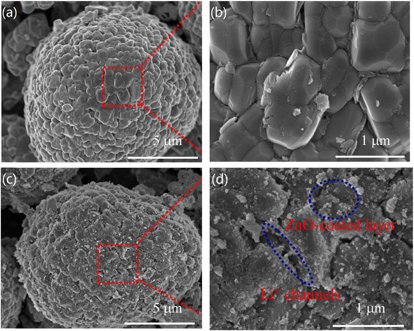
pristine samples. The reason for the improvement of More detailed structural features of the pristine and
cycling performance is that ZnO-coated layer works as 1 wt% ZnO-coated LiNi0.8Co0.15Al0.05O2 were explored by
an isolating layer, which effectively reduces the side high-resolution TEM. The pristine sample shows smooth
reactions between electrode and electrolyte, inhibits the surface and clear lattice fringes, indicating high crystal-
internal collapse of the structure caused by the dissolu- lization (Figure 8a). The inter planar distance of pristine
tion of transition metals [32], improves the structural sta- sample is about 0.47 nm (Figure 8b), corresponding to
bility of the material, and further improves the cycling the planar distance of the (003) plane in XRD patterns
performance of LiNi0.8Co0.15Al0.05O2 cathode material. In [33]. As shown in Figure 8c and d, it is obvious that the
addition, the thin ZnO-coated layer can improve the dif- ZnO nanoparticles are attached to the surface of the
fusion rate of Li+ and the conductivity of the electrode. LiNi0.8Co0.15Al0.05O2, which is consistent with the result
This result will be verified by CV and EIS. However, the of the SEM image. As anticipated, this coating layer
cycling performance of Z2 and Z3 is slightly lower than should improve electrochemical performances of LiNi0.8-
that of Z1 after 100 cycles, indicating that the thick Co0.15Al0.05O2 by protecting its surface from electrolyte
coating will hinder the diffusion of Li+ to a certain extent. corrosion and HF attack.
Figure 5: (a) XRD patterns of the pristine and ZnO-coated LiNi0.8Co0.15Al0.05O2, (b) standard XRD pattern of ZnO.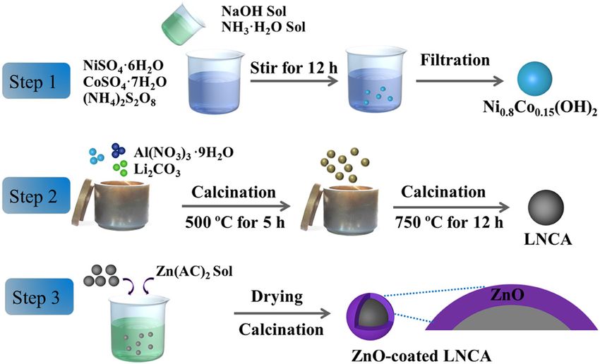
Improvement of cathode material performance by ZnO coating 215
200 ZnO-coated LiNi0.8Co0.15Al0.05O2 is obviously better than
that of the pristine one. At the current rate of 10C, ZnO-
Discharge capacity/mAh g-1
160 coated LiNi0.8Co0.15Al0.05O2 shows a higher discharge capa-
city of 135 mA h g−1 than that of the pristine sample (115 mA h g−1).
120 In general, the ZnO-coated LiNi0.8Co0.15Al0.05O2 has ZnO
protective layer, which can reduce the interfacial impe-
dance, inhibit the electrochemical polarization, and hence
80
Z0 Pristine sample improve the rate performance.
Z1 1wt% ZnO-coated Figure 10 shows the CV of the pristine and ZnO-
40 Z2 2wt% ZnO-coated coated LiNi0.8Co0.15Al0.05O2 after 10 cycles with a scan-
Z3 3wt% ZnO-coated
ning rate of 0.1 mV s−1 in a voltage range of 3.0–4.3 V.
0 Those two curves show the unique redox couples of
0 10 20 30 40 50 60 70 80 90 100
Cycle number Nickel-based compounds [34]. The three pairs of redox
peaks from left to right correspond to Ni2+/Ni3+, Ni3+/Ni4+,
Figure 6: Cycling performance of the pristine and ZnO-coated and Co3+/Co4+ [35]. In the anodic process, the peak
LiNi0.8Co0.15Al0.05O2 samples at 0.2C.
located at about 3.76 V corresponds to phase transition
from the hexagonal phase (H1) to the monoclinic phase
(M), the peak at about 4.00 V corresponds to the phase
The rate performance tests of pristine and ZnO-coated transition from M to a new hexagonal phase (H2), and
LiNi0.8Co0.15Al0.05O2 were conducted under different cur- the peak at about 4.18 V corresponds to the phase transi-
rent rates (0.2, 0.5, 1, 3, 5, 10C) in the voltage range of tion from the H2 to another hexagonal phase (H3) [36].
2.8–4.3 V. As shown in Figure 9, at a low current rate of There is no other peak in the curves of the ZnO-coated
0.2C, the discharge capacity of the ZnO-coated LiNi0.8- LiNi0.8Co0.15Al0.05O2, indicating that the modification of
Co0.15Al0.05O2 is not significantly improved. However, as ZnO does not affect the structure of LiNi0.8Co0.15Al0.05O2
the current density increases, the rate performance of cathode material.
Figure 7: SEM images of the (a and b) pristine and (c and d) 1 wt% ZnO-coated LiNi0.8Co0.15Al0.05O2 samples.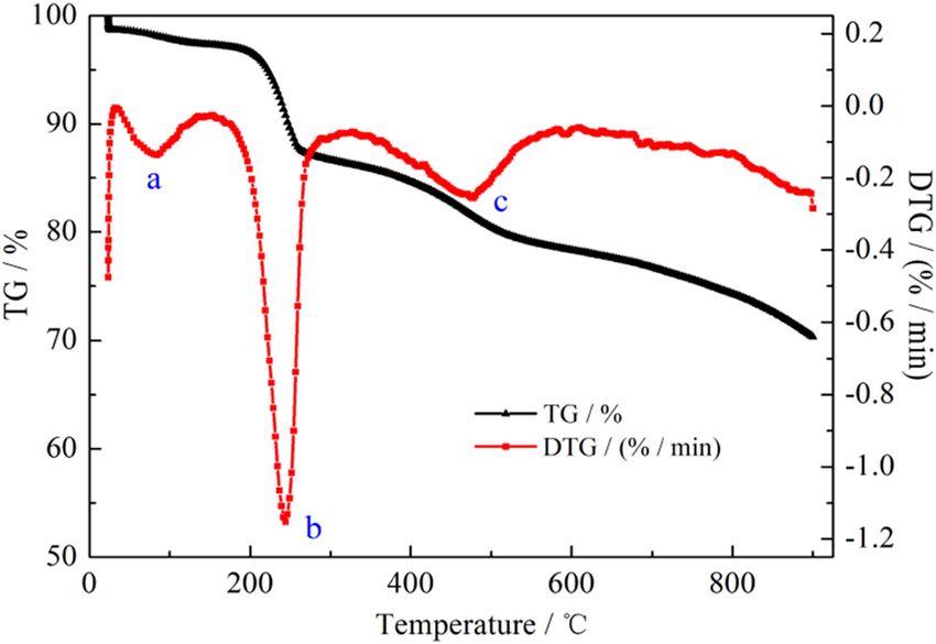
216 Fangfang Wang et al.
Figure 8: TEM images of (a and b) pristine and (c and d) ZnO-coated LiNi0.8Co0.15Al0.05O2.
To further investigate the reasons for the improve- when the scanning rate is 0.8 mV s−1, the ΔV of the
ment of rate performance, the CV measurements were main peak (Ni3+/Ni4+, located at about 3.8 V) of ZnO-
performed at various scanning rates. The potential inter- coated LiNi0.8Co0.15Al0.05O2 is 0.37 V, smaller than that
vals (ΔV) between the anodic and cathodic peaks indicate of the pristine sample (0.43 V), which indicated that
the reversibility of Li+ insertion/extraction and electrode the modification of ZnO can inhibit the electrode polari-
polarization [37]. As shown in Figure 11a and b, ΔV zation and improve the electrochemical reversibility
increases with the increase of the scanning rate, and [38]. As shown in Figure 11c and d, the linear relationship
between the redox peak current (ip) and the square root of
Figure 9: Rate performance of pristine and ZnO-coated Figure 10: CV curves of pristine and ZnO-coated LiNi0.8Co0.15Al0.05O2
LiNi0.8Co0.15Al0.05O2 samples. samples at a scanning rate of 0.1 mV s−1 in the voltage of 3.0–4.3 V.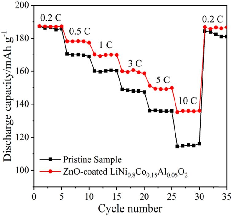
Improvement of cathode material performance by ZnO coating 217
Figure 11: Cyclic voltammogram of (a) pristine and (b) ZnO-coated LiNi0.8Co0.15Al0.05O2 at various scanning rates; linear relationship
between the peak currents (ip) and square root of scan rate (ν1/2): (c) pristine sample, (d) ZnO-coated LiNi0.8Co0.15Al0.05O2 sample.
scanning rate (ν1/2) is employed to calculate the Li+ diffu- literature [39]. The DLi+ is calculated by the following
sion coefficient (DLi+ ) of the main peak (Ni3+/Ni4+, located equation:
at about 3.7 V), which is the same method used in the
ip = 2.69 × 10 5n3 / 2ADLi1/ 2 C∗v1 / 2
Figure 12: Nyquist plots of (a) pristine and (b) ZnO-coated LiNi0.8Co0.15Al0.05O2 samples after different cycles, (c) equivalent circuit model.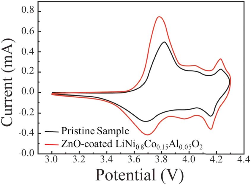
218 Fangfang Wang et al.
Table 3: EIS parameters of pristine and ZnO-coated First of all, the addition of (NH4)2S2O8 reduces the cation
LiNi0.8Co0.15Al0.05O2 after different cycles mixing of LiNi0.8Co0.15Al0.05O2; solid-phase Al-doping
improves the element distribution and layered structure.
Sample Cycle Rs (Ω) Rf (Ω) Rct (Ω) Then, optimizing the calcination temperature enhances
number
the crystallinity of LiNi0.8Co0.15Al0.05O2, and the ZnO was
LiNi0.8Co0.15Al0.05O2 0 5.825 15.456 233.31 coated on the surface of LiNi0.8Co0.15Al0.05O2 to improve
10 3.164 12.146 65 the cycling performance. The electrochemical tests demon-
100 4.163 16.428 172.5
strated a high reversible discharge capacity of 172.1 mA h g−1
ZnO-coated 0 4.125 14.943 151
LiNi0.8Co0.15Al0.05O2 10 2.823 6.962 28
at 0.2C with the capacity retention of 91.3% after 100 cycles
100 3.426 10.944 62.8 and a good rate performance at high current density.
The above-mentioned improvement indicates the potential
application of ZnO-coated LiNi0.8Co0.15Al0.05O2 as the cathode
where, the n is charge-transfer number, and C* is the material for advanced LIBs.
concentration of Li+ in the active material. The DLi+ at
the oxidation peak and the reduction peak of the initial Funding information: This research was financially sup-
sample are 1.89 × 10⁻¹⁰ and 1.47 × 10⁻¹⁰ cm2 s−1, respectively, ported by Minjiang Scholarship of Fujian Province
which is smaller than that of ZnO-coated LiNi0.8Co0.15Al0.05O2 (No. Min-Gaojiao[2010]-117), Central-government Guided
(2.21 × 10⁻¹⁰ and 1.71 × 10⁻¹⁰ cm2 s−1). The diffusion control Fund for Local Economic Development (No. 830170778),
dominates the electrochemical reaction during the Li+ inser- R&D Fund for Strategic Emerging Industry of Fujian
tion/extraction progress. Therefore, the modification of ZnO Province (No. 82918001), and International Cooperation
improves the rate performance. Project of Fujian Science and Technology Department
Figure 12 shows the Nyquist plots of the pristine and (No. 830170771).
ZnO-coated LiNi0.8Co0.15Al0.05O2 samples before and after
10 and 100 cycles. The equivalent circuit model of the Author contributions: All authors have accepted respon-
studied system is also shown in Figure 9d. Rs represents sibility for the entire content of this manuscript and
the resistance of the electrolyte, Rf means the surface film approved its submission.
resistance, Rct is the charge-transfer resistance [40], and
W is the Warburg impedance that reflects the diffusion of Conflict of interest: David Hui, who is the coauthor
Li+ in the solid [41]. of this article, is a current Editorial Board member of
All the fitted EIS parameters are listed in Table 3. It is Nanotechnology Reviews. This fact did not affect the
noted that these two samples both show a large Rct value peer-review process. The authors declare no other con-
before cycling, which is caused by the inactivation of the flict of interest.
electrodes [42]. As the cycling test begins, the Rct value
decreases rapidly during the internal activation process
[43]. However, after 100 cycles, the Rct value of the pris-
tine sample quickly increased to 172.5 Ω, which was much References
higher than that of after 10th cycle. However, the value
of Rct for ZnO-coated LiNi0.8Co0.15Al0.05O2 after 100 cycles [1] Lin D, Liu Y, Cui Y. Reviving the lithium metal anode for high-
is only about 62.8 Ω, much smaller than that of the pris- energy batteries. Nat Nanotechnol. 2017;12:194–206.
tine one. It can be concluded from the experimental [2] Cano ZP, Banham D, Ye S, Hintennach A, Lu J, Fowler M, et al.
Batteries and fuel cells for emerging electric vehicle markets.
results that the ZnO-coated layer decreases the charge-
Nat Energy. 2018;3:279–89.
transfer resistance, increases the electronic conductivity [3] Pfleging W. A review of laser electrode processing for devel-
of LiNi0.8Co0.15Al0.05O2, and further improves the rate opment and manufacturing of lithium-ion batteries.
performance. Nanotechnol Rev. 2018;7(3):549–73.
[4] Lee MJ, Noh M, Park MH, Jo M, Kim H, Nam H, et al. The role of
nanoscale-range vanadium treatment in LiNi0.8Co0.15Al0.05O2
cathode materials for Li-ion batteries at elevated tempera-
4 Conclusion [5]
tures. J Mater Chem. 2015;3:13450–53.
Gao S, Cheng YT, Shirpour M. Effects of cobalt deficiency on
nickel-rich layered LiNi0.8Co0.1Mn0.1O2 positive electrode
In conclusion, we designed a novel method for the pre- materials for lithium-ion batteries. ACS Appl Mater Inter.
paration of high-capacity LiNiO2-based cathode materials. 2019;11:982–9.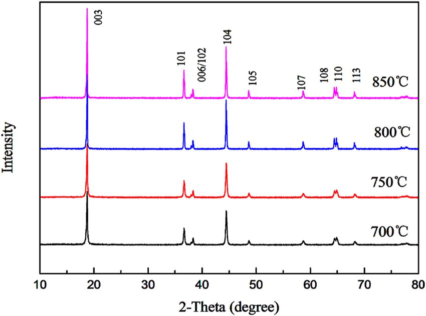
Improvement of cathode material performance by ZnO coating 219
[6] Novikova SA, Yaroslavtsev AB. Cathode materials based on [22] Kim Y, Kim D. Synthesis of high-density nickel cobalt alu-
olivine lithium iron phosphates for lithium-ion batteries. minum hydroxide by continuous coprecipitation method.
Rev Adv Mater Sci. 2017;49(2):129–39. ACS Appl Mater Inter. 2012;4(2):586.
[7] Augustyn V, Therese S, Turner TC, Manthiram A. Nickel-rich [23] Zhang W, Chi ZX, Mao WX, Lv RW, Cao AM, Wan LJ, et al. One-
layered LiNi1−xMxO2 (M = Mn, Fe, and Co) electrocatalysts with nanometer-precision control of Al2O3 nanoshell through
high oxygen evolution reaction activity. J Mater Chem. solution-based synthesis route. Angew Chem Int Ed.
2015;3:16604–12. 2014;53:12776–80.
[8] Shi JL, Xiao DD, Zhang XD, Yin YX, Guo YG, Gu L, et al. Improving [24] Zhu B, Liu N, Mcdowell M, Jin Y, Cui Y, Zhu J, et al. Interfacial
the structural stability of Li-rich cathode materials via reservation stabilizing effect of ZnO on Si anodes for lithium ion battery.
of cations in the Li-slab for Li-ion batteries. Nano Res. 2017;12:1–9. Nano Energy. 2015;13:620–25.
[9] Li LJ, Chen ZY, Zhang QB, Xu M, Zhou X, Zhu HL, et al. A [25] Liang L, Hu G, Jiang F, Cao Y. Electrochemical behaviours of
hydrolysis-hydrothermal route for the synthesis of ultrathin SiO2-coated LiNi0.8Co0.1Mn0.1O2 cathode materials by a novel
LiAlO2-inlaid LiNi0.5Co0.2Mn0.3O2 as a high-performance modification method. J Alloy Compound. 2016;657:570–81.
cathode material for lithium ion batteries. J Mater Chem. [26] Liu X, Wang S, Wang L, Wang K, Wu XZ, Zhou PF, et al.
2015;3:894–904. Stabilizing the high-voltage cycle performance of
[10] Makimura Y, Sasaki T, Nonaka T, Nishimura YF, Uyama T, LiNi0.8Co0.1Mn0.1O2 cathode material by Mg doping. J Power
Okuda C, et al. Factors affecting cycling life of LiNi0.8Co0.15Al0.05O2 Sources. 2019;438(31):227017–24.
for lithium-ion batteries. J Mater Chem. 2016;4:8350–58. [27] Yu W, Huang L, Yang D, Fu P, Zhou L, Zhang J, et al. Efficiency
[11] Zhang HZ, Liu C, Song DW, Zhang LQ, Bie LJ. A new synthesis exceeding 10% for inverted polymer solar cells with a ZnO/
strategy towards enhancing the structure and cycle stabilities ionic liquid combined cathode interfacial layer. J Mater Chem.
of the LiNi0.80Co0.15Al0.05O2 cathode material. J Mater Chem. 2015;A310:660–65.
2017;5:835–41. [28] Huang XR, Zeng LJ, Li RF, Xi ZJ, Li YC. Manipulating conductive
[12] Wu NT, Wu H, Yuan W, Liu SJ, Liao JY, Zhang Y, et al. Facile network formation via 3D T-ZnO: A facile approach for a CNT-
synthesis of one-dimensional LiNi0.9Co0.07Al0.03O2 microrods reinforced nanocomposite. Nanotechnol Rev. 2020;9:534–42.
as advanced cathode materials for lithium ion batteries. [29] Fu CC, Li GS, Luo D, Li Q, Fan JM, Li LP, et al. Nickel-rich layered
J Mater Chem. 2015;3:13648–52. microspheres cathodes: lithium/nickel disordering and electro-
[13] Song X, Liu GX, Yue HF, Luo L, Yang SY, Huang YY, et al. A novel chemical performance. ACS Appl Mater Inter. 2014;6:15822–31.
low-cobalt long-life LiNi0.88Co0.06Mn0.03Al0.03O2 cathode [30] Yu HJ, Qian YM, Otani M, Tang DM, Guo SH, Zhu YB, et al. Study
material for lithium ion batteries. Chem Eng J. of the lithium/nickel ions exchange in the layered
2020;407:126301–10. LiNi0.42Mn0.42Co0.16O2 cathode material for lithium ion bat-
[14] Liu W, Oh P, Liu X, Lee MJ, Cho W, Chae S, et al. Nickel-rich teries: experimental and first-principles calculations. Energy
layered lithium transition-metal oxide for high-energy lithium- Environ Sci. 2014;7:1068–78.
ion batteries. Angew Chem Int Ed. 2015;127:4518–36. [31] Wu F, Tian J, Su Y, Wang J, Zhang C, Bao L, et al. Effect of Ni(2+)
[15] Chen M, Zhao EY, Chen DF, Wu MM, Han SB, Huang QZ, et al. content on lithium/nickel disorder for Ni-rich cathode mate-
Decreasing Li/Ni disorder and improving the electrochemical rials. ACS Appl Mater Inter. 2015;7(14):7702–08.
performances of Ni-Rich LiNi0.8Co0.1Mn0.1O2 by Ca doping. [32] Zhao EY, Liu XF, Zhao H, Xiao XL, Hu ZB. Ion conducting
Inorg Chem. 2017;56:8355–62. Li2SiO3-coated lithium-rich layered oxide exhibiting high rate
[16] Jo M, Noh M, Oh P, Kim Y, Cho J. A new high power capability and low polarization. Chem Commun.
LiNi0.81Co0.1Al0.09O2 cathode material for lithium-ion batteries. 2015;51:9093–96.
Adv Energy Mater. 2014;4:1301583. [33] Zhao E, Chen M, Chen D, Xiao X, Hu Z. A versatile coating
[17] Chen WH, Li YY, Yang D, Feng XM, Guan XX, Mi LW, et al. strategy to highly improve the electrochemical properties of
Controlled synthesis of spherical hierarchical Li–Ni1−x layered oxide LiMO2 (M = Ni0.5Mn0.5 and Ni1/3Mn1/3Co1/3).
−yCoxAlyO2 (0 < x, y < 0.2) via a novel cation exchange process ACS Appl Mater Inter. 2015;7(49):27096–105.
as cathode materials for high-performance lithium batteries. [34] Qiu Z, Zhang Y, Dong P, Xia S, Yao Y. A facile method for
Electrochim Acta. 2016;190:932–38. synthesis of LiNi0.8Co0.15Al0.05O2 cathode material. Solid State
[18] Bak SM, Nam KW, Chang WY, Yu XQ, Hu EY, Hwang S, et al. Ionics. 2017;307:73–8.
Correlating structural changes and gas evolution during the [35] Li LJ, Li XH, Wang ZX, Guo HJ, Yue P, Chen W, et al. Synthesis,
thermal decomposition of charged LixNi0.8Co0.15Al0.05O2 structural and electrochemical properties of
cathode materials. Chem Mater. 2013;25:337–51. LiNi0.79Co0.1Mn0.1Cr0.01O2 via fast co-precipitation. J Alloys
[19] Trease NM, Seymour ID, Radin MD, Liu H, Hao L, Hy S, et al. Compd. 2010;507(1):172–77.
Identifying the distribution of Al3+ in LiNi0.8Co0.15Al0.05O2. [36] Noh HJ, Youn S, Yoon CS, Sun YK. Comparison of the structural
Chem Mater. 2016;28(22):870–80. and electrochemical properties of layered Li[NixCoyMnz]-O2
[20] Liang M, Song D, Zhang H. Improved performances of (x = 1/3, 0.5, 0.6, 0.7, 0.8 and 0.85) cathode material for
LiNi0.8Co0.15Al0.05O2 material employing NaAlO2 as a new lithium-ion batteries. J Power Sources. 2013;233:121–30.
aluminium source. ACS Appl Mater Inter. 2017;9:7b12306. [37] Xie H, Hu G, Du K, Peng Z, Cao Y. An improved continuous
[21] Zhou P, Meng H, Zhang Z, Chen CC, Lu Y, Cao J, et al. Stable co-precipitation method to synthesize LiNi0.8Co0.15Al0.05O2
layered Ni-rich LiNi0.9Co0.07Al0.03O2 microspheres assembled cathode material. J Alloy Compound. 2016;666:84–7.
with nanoparticles as high-performance cathode materials for [38] Rui XH, Ding N, Liu J, Li C, Chen CH. Analysis of the chemical
lithium-ion batteries. J Mater Chem A Mater Energ Sus. diffusion coefficient of lithium ions in Li3V2(PO4)3 cathode
2017;5(6):2724–31. material. Electrochim Acta. 2010;55:2384–90.220 Fangfang Wang et al.
[39] Chen CC, Huang YN, An CH, Zhang H, Wang YJ, Jiao LF, et al. cathode, Li(MMn11/6)O4 (M = Mn1/6, Co1/6, (Co1/12Cr1/12)).
Copper-doped dual phase Li4Ti5O12-TiO2 nanosheets as high- J Phys Chem C. 2013;117:9056–64.
rate and long cycle life anodes for high-power lithium-ion [42] Zhang Q, Sha ZF, Cui X, Qiu SQ, He CG, Zhang JL, et al.
batteries. ChemSusChem. 2015;8:114–22. Incorporation of redox-active polyimide binder into LiFePO4
[40] Stenina IA, Kulova TL, Skundin AM, Yaroslavtsev AB. Carbon cathode for high-rate electrochemical energy storage.
composites as anode materials for lithium-ion batteries. Nanotechnol Rev. 2020;9:1350–58.
Rev Adv Mater Sci. 2017;49:140–49. [43] Levi MD, Aurbach D. Impedance of a single intercalation par-
[41] Reddy MV, Sakunthala A, Pandian SS, Chowdari BVR. ticle and of non-homogeneous, multilayered porous compo-
Preparation, comparative energy storage properties, and site electrodes for Li-ion batteries. J Phys Chem B.
impedance spectroscopy studies of environmentally friendly 2004;108:11693–703.You can also read