Flex Max RF Amplifiers - DATA SHEET
←
→
Page content transcription
If your browser does not render page correctly, please read the page content below
DATA SHEET
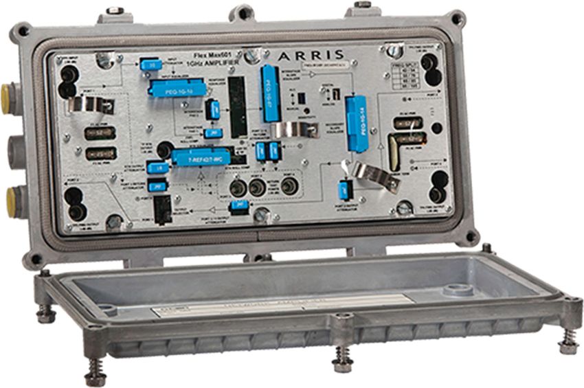
Flex Max® RF Amplifiers
FM601e-T/B
1 GHz Trunk and Bridger Amplifiers
FEATURES For cable operators looking to ensure scalability, maximum backward
compatibility, and protect network investments, CommScope offers
• Simplify plant upgrades with modular RF design solutions that deliver new services with minimal CAPEX, enhance
• Improve amplifier reach with optional GaN network efficiency, and increase subscriber satisfaction.
technology and increased station tilt CommScope Flex Max® FM601e‐T/B 1 GHz Trunk and Bridger Amplifiers
• Maintain current amplifier spacing with high utilize the Philips 9‐NH15 style housing base. Featuring 1 GHz GaAs
output GaAs technology technology, the FM601e‐T/B is available as a complete unit for
• Expand return path bandwidth with plug‐in greenfield deployments or as a drop‐in RF module for Philips 9‐NH
diplex filter support to 85 MHz series housings. Units include one active high level trunk output and
• Minimize RF drift over temperature with one active high level bridger output configurable to two outputs via an
standard analog or QAM ALC output port distribution accessory. The FM601e‐T/B also provides two
active high level outputs configurable to three outputs via an output
port distribution accessory. Optional GaN (Gallium Nitrite) technology
for higher output capability is available on the FM601e Bridger. In
addition, the FM601e‐T/B is compatible with 750/870 MHz EQs and
Pads, allowing operators to extend or upgrade GNA/TNA or
G3A/T3A/G4A amplifier networks quickly and easily using common
plug‐ins.
1 FM601e-T/B © 2021 CommScope, Inc. All rights reserved.
CommScope also offers a QAM Channel Automatic Level Control (ALC) Pilot Frequency option, which is available with or without a
      gain hold feature, for Flex Max Amplifiers. An option with the gain hold feature enables an amplifier to adjust output levels to the
      mid‐range automatically if its pilot level drops by 10 dB or more. The ALC Pilot Frequency option allows operators to choose
      between 609 MHz or 711 MHz pilot frequencies.

      PLATFORM COMPATIBILITY
       Platform                                   Philips Diamond Line   6‐TNA       Philips Diamond Line      6‐GNA                   FM601
                                                          I (T3A)                         II (G3A,G4A)
       Upgrade to FM601e                                 Yes*             Yes*               Yes*                Yes*                     Yes
       *Requires 15A Seizure Pin (PN 0512842‐3)

      HOUSING COMPATIBILITY
       Housing                                                  7‐NH                           9‐NH                             9‐NH15
       Upgrade to FM601e                                        Yes*                            Yes*                               Yes
       *Requires 15A Seizure Pin (PN 0512842‐3)

2   FM601e-T/B                                                                                                   © 2021 CommScope, Inc. All rights reserved.
BRIDGER SPECIFICATIONS GaAs (ALC)
Specifications Forward Return
Frequency Split, MHz 54–1002 5–42
85–1002 5–65
105–100213 5–85
Flatness, dB ± 1.0 ± 0.75
Full Gain (without EQ and ALC), dB 48 19
Operation Gain (‐0,+1.0 dB), dB1,2 43 18
ALC Control Range, dB +3.3/‐4.0 NA
Noise Figure (without EQ), dB3 9/9/8/10.8 15.5
Standard Slope Reference Frequency, MHz 1002/870/550/54 FMAXRTN/5
Reference Output Level, dBmV5,6 52/49.5/44/35 35/35
Operating Tilt, dB 17 ± 1.0 NA
Distortion: Analog/Digital Performance
Channels, Number of NTSC4 79 6
Composite Triple Beat (CTB), dBc 75 80
Cross Modulation (XM), dB 69 74
Composite Second Order (CSO), dBc 73 82
Carrier to Intermodulation Noise (CIN), dB8 63 —
Distortion: All Digital
Channels, Number of 256 QAM9 154 —
Carrier to Intermodulation Noise (CIN), dB10 63 —
Test Point Accuracy (‐20 dB), dB
Input, Output Test Point ± 0.5 (54–550), ± 1.0 (550–1002) ± 0.75 (5–FMAXRTN)
Return Loss, dB11 16 16
Hum Modulation @ 15A, dBc
5–10 MHz — 55
11–750 MHz 65 65
751–1002 MHz 60 —
DC Voltage, VDC 24 ± 0.5
Current DC Max, mA 1650
Power Consumption Max, W Vin is between 67 and 90 VAC
Then Iac = Idc x 0.41
Vin is between 36 and 67
Iac = (Idc x 27.5)/VAC
Input Voltage Range, VAC
90 VAC HFC 45–90
HFC AC Current Draw Max, A12
@ 90 VAC 0.677
@ 60 VAC 1.02
AC Bypass Current (all ports), A 15
Chrominance/Luminance Delay, ns/3.58 MHz
Channel 2 28 —
Channel 3 11 —
Channel 4 7 —
Channel 5 3.6 —
Return Group Delay, ns
5.5–7 MHz — 55
10–11.5 MHz — 11
35–36.5 MHz — 10
38.5–40 MHz — 30
3 FM601e-T/B © 2021 CommScope, Inc. All rights reserved.BRIDGER SPECIFICATIONS GaN (ALC)
Specifications Forward Return
Frequency Split, MHz 54–1002 5–42
85–1002 5–65
105–100213 5–85
Flatness, dB ± 1.0 ± 0.75
Full Gain (without EQ and ALC), dB 48 19
Operation Gain (‐0,+1.5 dB), dB1,2 43 18
ALC Control Range, dB +3.3/‐4.0 NA
Noise Figure (without EQ), dB3 9/9/8/10.8 15.5
Standard Slope Reference Frequency, MHz 1002/870/550/54 FMAXRTN/5
Reference Output Level, dBmV5,7 56/53.5/48/39 35/35
Operating Tilt, dB 17 ± 1.0 NA
Distortion: Analog/Digital Performance
Channels, Number of NTSC4 79 6
Composite Triple Beat (CTB), dBc 73 80
Cross Modulation (XM), dB 64 74
Composite Second Order (CSO), dBc 72 82
Carrier to Intermodulation Noise (CIN), dB8 56 —
Distortion: All Digital
Channels, Number of 256 QAM9 154 —
Carrier to Intermodulation Noise (CIN), dB10 56 —
Test Point Accuracy (‐20 dB), dB
Input, Output Test Point ± 0.5 (54–550), ± 1.0 (550–1002) ± 0.75 (5–FMAXRTN)
Return Loss, dB11 16 16
Hum Modulation @ 15A, dBc
5–10 MHz — 55
11–750 MHz 65 65
751–1002 MHz 60 —
DC Voltage, VDC 24 ± 0.5
Current DC Max, mA 1650
Power Consumption Max, W Vin is between 67 and 90 VAC
Then Iac = Idc x 0.41
Vin is between 36 and 67
Iac = (Idc x 27.5)/VAC
Input Voltage Range, VAC
90 VAC HFC 45–90
HFC AC Current Draw Max, A12
@ 90 VAC 0.677
@ 60 VAC 1.02
AC Bypass Current (all ports), A 15
Chrominance/Luminance Delay, ns/3.58 MHz
Channel 2 28 —
Channel 3 11 —
Channel 4 7 —
Channel 5 3.6 —
Return Group Delay, ns
5.5–7 MHz — 55
10–11.5 MHz — 11
35–36.5 MHz — 10
38.5–40 MHz — 30
4 FM601e-T/B © 2021 CommScope, Inc. All rights reserved.TRUNK SPECIFICATIONS GaAs (ALC)
Specifications Forward Return
Trunk Bridger
Frequency Split, MHz 54–1002 5–42
85–1002 5–65
105–100213 5–85
Flatness, dB ± 1.0 ± 0.75
Full Gain (without EQ and ALC), dB 36 45 19
Operation Gain (‐0, +1.0 dB), dB1,2 32 41 18
ALC Control Range, dB +3.3/‐4.0 NA
Noise Figure (without EQ), dB3 9/9/8.5/10.5 15.5
Standard Slope Reference Frequency, MHz 1002/870/550/54 FMAXRTN/5
Reference Output Level, dBmV5,6 40.5/39/34/27 49.5/48/43/36 35/35
Operating Tilt, dB 17 ± 1.0 NA
Distortion: Analog/Digital Performance
Channels, Number of NTSC4 79 79 6
Composite Triple Beat (CTB), dBc 81 72 80
Cross Modulation (XM), dB 76 67 74
Composite Second Order (CSO), dBc 78 73 82
Carrier to Intermodulation Noise (CIN), dB8 79 63 —
Distortion: All Digital
Channels, Number of 256 QAM9 154 154 —
Carrier to Intermodulation Noise (CIN), dB10 63 63 —
Test Point Accuracy (‐20 dB), dB
Input, Output Test Point ± 0.5 (54–550), ± 1.0 (550–1002) ± 0.75 (5–FMAXRTN)
Return Loss, dB11 16 16
Hum Modulation @ 15A, dBc
5–10 MHz — 55
11–750 MHz 65 65
751–1002 MHz 60 —
DC Voltage, VDC 24 ± 0.5
Current DC Max, mA 1650
Power Consumption Max, W Vin is between 67 and 90 VAC
Then Iac = Idc x 0.41
Vin is between 36 and 67
Iac = (Idc x 27.5)/VAC
Input Voltage Range, VAC
90 VAC HFC 45–90
HFC AC Current Draw Max, A12
@ 90 VAC 0.677
@ 60 VAC 1.02
AC Bypass Current (all ports), A 15
Chrominance/Luminance Delay, ns/3.58 MHz
Channel 2 28 —
Channel 3 11 —
Channel 4 7 —
Channel 5 3.6 —
Return Group Delay, ns
5.5–7 MHz — 55
10–11.5 MHz — 11
35–36.5 MHz — 10
38.5–40 MHz — 30
5 FM601e-T/B © 2021 CommScope, Inc. All rights reserved.SPECIFICATIONS MECHANICAL
Specifications
Operating Temperature Range ‐40° to +60°C
‐40° to +140°F
Housing Dimensions, L x W x D 15.5 L x 9.1 W x 5.3 D inches
394 L x 231 W x 135 D mm
Weight 15.9 lb
7.2 kg
NOTES:
1. Forward spacing at highest frequency with PEQ‐1G‐xx equalizer installed.
2. Return spacing is with a 0 dB attenuator installed in the return EQ location. Return EQ circuitry is built into main PCB. As the attenuator value increases, the return equalization
insertion loss at FMAXRTN MHz also increases.
3. The noise figure specification is “Typical” within specified passband.
4. Analog channels occupying the 54 to 550 MHz frequency range with 256‐QAM channels to 1002 MHz at ‐6 dBc below equivalent video channels.
5. Recommended maximum return output level includes loss due to equalizer.
6. At specified operational tilt, maximum equivalent analog output level for 1 GHz loading is 56.5 dBmV @ HF for GaAs.
7. At specified operational tilt, maximum equivalent analog output level for 1 GHz loading is 59 dBmV @ HF for GaN.
8. Systems operating with digitally compressed channels or equivalent broadband noise from 550 to 1002 MHz at levels 6 dB below equivalent video channels will experience a
composite intermodulation distortion (CIN) appearing as noise in the 54 to 550 MHz frequency spectrum.
9. 256‐QAM channels occupy 54 to 1002 MHz with 3 channels replaced by analog channels for CCNR measurement.
10. Systems operating with digitally compressed channels from 54 to 1002 MHz at levels 6 dB below equivalent video channels will experience a composite intermodulation distortion
(CIN) appearing as noise relative to any remaining analog channels.
11. Output return loss may derate to 15 dB above 600 MHz.
12. The power supply is internal to the RF module. Refer to drawing #333995‐37.
For 60 VAC powering: AC power consumption in watts divided by a factor of 43 = Amps required.
For 90 VAC powering: 67 VAC, 1.03 x (AC power consumption in watts divided by voltage) = Amps required.
For 67 to 90 VAC, AC power consumption in watts divided by 65 = Amps required.
13. For frequency split 85/105 MHz roll‐off from 105 MHz to 102 MHz < 1.0 dB. Group delay from 103.25 MHz to 105.25 MHz is < 22 ns
REQUIRED ACCESSORIES
Part Number Description
PEQ‐1G‐00 One of the following per FM601e Forward 1002 MHz equalizer (0 dB) ‐or‐
PEQ‐1G‐XX Forward 1002 MHz equalizer (values 2 to 20 dB in 1 dB steps) ‐or‐
PCS‐1G‐XX Cable simulator (values 2 to 12 dB in 1 dB steps)
7‐REFxx/x‐WC Plug‐in Return Equalizer (values 1 to 9 dB in 1 dB steps)
10Axx.0‐WC Plug‐in Attenuators (values 0 to 26 dB in 1 dB steps)
OPTIONAL ACCESSORIES
Part Number Description
0512842‐3 FM601/TNA/GNA/DL – 15 Amp Seizure Pin with spacer
RELATED PRODUCTS
FM321e‐LE FM601e‐LE
FM901e‐T/B STARLINE™ RF Amplifiers
FM331‐LE Installation Services
Contact Customer Care for product information and sales:
• United States: 866‐36‐ARRIS
• International: +1‐678‐473‐5656
Note: Specifications are subject to change without notice.
Copyright Statement: © 2021 CommScope, Inc. All rights reserved. ARRIS, the ARRIS logo, Flex Max, and STARLINE are trademarks of CommScope, Inc. and/or its affiliates. All other trademarks are the property of their respective
owners. No part of this content may be reproduced in any form or by any means or used to make any derivative work (such as translation, transformation, or adaptation) without written permission from CommScope, Inc and/or
its affiliates (“CommScope”). CommScope reserves the right to revise or change this content from time to time without obligation on the part of CommScope to provide notification of such revision or change.
FM601eTB_DS_17SEP21
6 FM601e-T/B 09‐2021You can also read